GE Profile DPVH890EJ How to use

GE Appliances
General Electric Company
Louisville, Kentucky 40225
31-9185
Profile Dryer
With Steam
DPVH890EJ
DPVH890GJ
Technical Service Guide
March 2009
GE Consumer & Industrial
ELICATS
D
OWER
P
WARM UP
SENSORDRY
S
TEAM
R
EFRESH
S
RYER
R
ACK
D
ELAY
S
TART
S
ETTINGS
IME
T
RY
D
IME
T
RY
D
STEAM
DEWRINKLE
PEED
S
RY
D
CTIVE
A
EAR
W
OTTONS
C
DAMP
ALERT
MY
CYCLEEXTEND
TUMBLE
DRUM
LIGHT
LOCK
XTRA
E
RY
D
RY
D
RY
D
OST
M
ACK
B
AMP
D
NTI-
A
ACREAL
B
IGH
H
EDIUM
M
OW
L
ENSOR
S
RY
D
EVEL
L
EMP
T
RY
D
XTRA
E
OW
L
RINKLEREE
WF
ORMAL /
N
IXEDOADS
ML
START
PAUSE
RY
D
ESS
L
SPECIALITY
CYCLES
Hold 3secstoStore

– 2 –
GE Consumer & Industrial
Technical Service Guide
Copyright © 2009
All rights reserved. This service guide may not be reproduced in whole or in part in
any form without written permission from the General Electric Company.
IMPORTANT SAFETY NOTICE
The information in this service guide is intended for use by individuals possessing
adequate backgrounds of electrical, electronic, and mechanical experience. Any
attempt to repair a major appliance may result in personal injury and property
damage. The manufacturer or seller cannot be responsible for the interpretation
of this information, nor can it assume any liability in connection with its use.
WARNING
If the information in this manual is not followed exactly, fire or explosion may result
causing property damage, personal injury or death. If you smell gas:
– Do not try to light any appliance.
– Do not touch any electrical switch; do not use any phone in the building.
– Immediately call the gas supplier from a neighbor’s phone. Follow the
gas supplier’s instructions.
– If you cannot reach the gas supplier, call the fire department.
WARNING
To avoid personal injury, disconnect power before servicing this product. If electrical
power is required for diagnosis or test purposes, disconnect the power immediately
after performing the necessary checks.
RECONNECT ALL GROUNDING DEVICES
If grounding wires, screws, straps, clips, nuts, or washers used to complete a path
to ground are removed for service, they must be returned to their original position
and properly fastened.

– 3 –
Table of Contents
Air Duct Assembly ............................................................................................................................................................14
Belt Switch............................................................................................................................................................................18
Blower Motor ......................................................................................................................................................................19
Blower Wheel......................................................................................................................................................................21
Burner Assembly and LP Conversion......................................................................................................................25
Component Locator Views........................................................................................................................................... 8
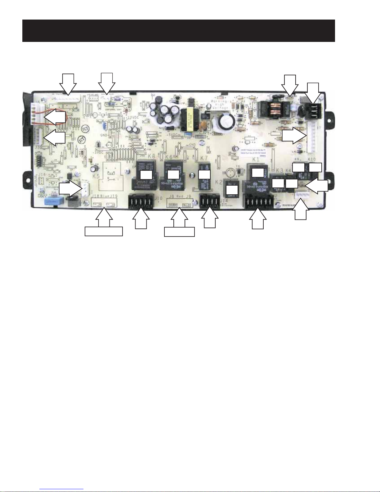
Control Board Assembly ...............................................................................................................................................33
Control Features............................................................................................................................................................... 6
Control Panel.......................................................................................................................................................................12
Display Board.....................................................................................................................................................................34
Door Switch ......................................................................................................................................................................... 15
Drive Belt...............................................................................................................................................................................16
Drum.......................................................................................................................................................................................17
Drum Motor.........................................................................................................................................................................18
Drum Shaft and Bearing................................................................................................................................................17
Drum Slide Assembly......................................................................................................................................................14
Dryer Components...........................................................................................................................................................12
Dual Idler Assembly.........................................................................................................................................................17
Error Codes .......................................................................................................................................................................... 43
Flame Detector ..................................................................................................................................................................27
Front Panel...........................................................................................................................................................................13
Gas Valve..............................................................................................................................................................................26
Gas Valve Coils...................................................................................................................................................................25
Heater Assembly...............................................................................................................................................................22
High Limit Thermostat....................................................................................................................................................31
Ignitor.....................................................................................................................................................................................27
Ignitor Circuit Operation................................................................................................................................................28
Inlet Control Thermistor.................................................................................................................................................30
Inlet Safety Thermostat.................................................................................................................................................30
Introduction......................................................................................................................................................................... 5
Moisture Sensor ................................................................................................................................................................15
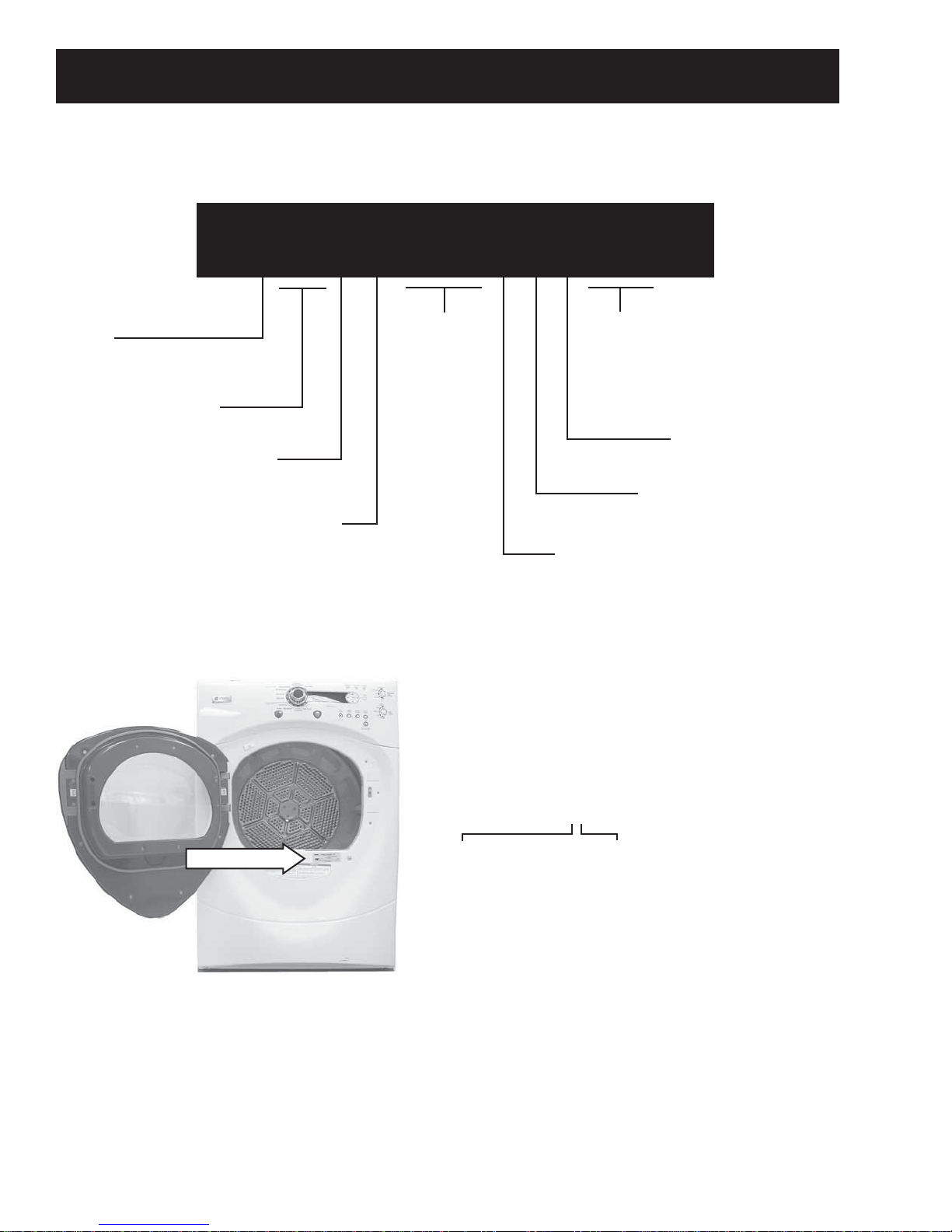
Nomenclature .................................................................................................................................................................... 4
Outlet Control Backup Thermostat...........................................................................................................................32
Outlet Control Thermistor .............................................................................................................................................31
Power Board........................................................................................................................................................................33
Power Board Connector Locator View....................................................................................................................10
Rack Dry Calrod®Element ...........................................................................................................................................29
Rack Dry Thermostat......................................................................................................................................................32
Schematics and Wiring Diagrams............................................................................................................................46
Service Test Mode.............................................................................................................................................................39
Steam Components.........................................................................................................................................................35
Steam Generator Assembly.........................................................................................................................................35
Steam Interlock Relay.....................................................................................................................................................37
Top Panel ..............................................................................................................................................................................13
Triac.........................................................................................................................................................................................22
Troubleshooting ................................................................................................................................................................39
Warranty ..............................................................................................................................................................................50
Water Fill Timer..................................................................................................................................................................38
Water Valve.........................................................................................................................................................................37

– 4 –
Nomenclature
The nomenclature tag is located on
the front panel inside the door.
Note: The technical sheet is located
inside the control panel.
Model Number
Capacity/Configuration
V = Very Big
D P V H 8 9 0 E J _ W W
Brand
D = General Electric
Feature Packages
P = Pedestal
Backsplash Control/Platform
H = Horizontal
Color
WW = White
MV = Vermillion (Red)
MG = Champagne
Engineering Revision
Alpha or Numeric
Model Year
J = 2008
Fuel/Voltage
E = 240V 60 Hz.
G = Gas 120V 60Hz.
Nomenclature
Control
Features
Note: The electric dryer DPVH890 is not recommended for 208V installation.
The letter designating
the year repeats every
12 years.
Example:
T - 1974
T - 1986
T - 1998
Serial Number
The first two numbers of the serial number
identify the month and year of manufacture.
Example: AS123456S = January, 2009
A- JAN 2009 - S
D - FEB 2008 - R
F - MAR 2007 - M
G - APR 2006 - L
H - MAY 2005 - H
L - JUN 2004 - G
M - JUL 2003 - F
R - AUG 2002 - D
S - SEP 2001 - A
T - OCT 2000 - Z
V - NOV 1999 - V
Z - DEC 1998 - T

– 5 –
Steam Dryer Features
Profile 890 model dryers introduce steam to the
drying cycle. Steam cycles, controlled by algorithms,
alternate between steam injection into the dryer drum
and dryer heat modes to loosen the fabric fibers and
effectively reduce wrinkles.
Located in the Timed Dry Cycles,
the steam cycles are:
Steam Refresh• - Freshens up
to five gently worn garments
in the dryer, removing
wrinkles and odors to extend
for another wear.
Steam Dewrinkle• - Helps
remove stubborn wrinkles
from fuller loads, quickly
and conveniently, even from
clothes left in the dryer from
the day before.
The steam injection system
consists of a water inlet valve,
water valve timer, steam
generator, and a steam outlet in
the drum slide assembly.
A "Y" connector on the cold water faucet supplies
water to the dryer. The water valve inlet is located at
the bottom left on the rear panel of the dryer. A hose
carries the water to the steam generator.
The steam generator assembly and the water valve
timer are located on the right side under the top panel.
An outlet hose connects the steam generator to the
steam outlet located in the drum slide assembly. The
steam generator is contained within a sealed inclosure
which protects the electrical equipment from water
and steam leaks. A drain hose evacuates any water
or steam leaked into the inclosure to the bottom right
front corner of the dryer.
The steam generator assembly contains 2
thermostats: a regulating thermostat (230°F) and a
safety thermostat (403°F). The steam generator boils
water to supply steam. The regulating thermostat
monitors the temperature and maintains it within the
working range. At 230°F, it activates a solid state timer
that opens the water valve for 4 seconds to add 2-1/4
ounces of water to the steam generator.
The steam generator assembly is replaced as a unit.
Introduction
Other Features Include:
Large 7.5-cubic foot dryer drum - Reverses•
direction during cycle.
Integrated Drying Rack for drying delicate•
items, such as washable
sweaters.
Drum Lamp•
My Cycle selection saves a•
favorite cycle for future use.
Built-in service test mode.•
Specific dryer components
can be operated. Error
codes are recorded and
accessible on the control
panel display.
Dual Thermistors -•
Thermistors are more
sensitive to temperature
changes and can relay the
information faster than
thermostats. The dryer
utilizes dual thermistors
to monitor incoming air
temperature as well as air
temperature leaving the drum. The sensors
work together with the variable heater and
the blower to provide consistent, even heat.
Moisture Sensor - The moisture sensor allows•
the control to monitor the fabric for moisture
content and end the cycle at the desired
moisture level.
Flush Door Handle•
Reversible Door (Kit included.)•
UV Stabilizers - The control panel, control•
panel cover, and door outer panel have UV
stabilizers to prevent yellowing when exposed
to sunlight.
The GE dryer can be installed on top of the GE•
Front Load Washer. (Stacking kit supplied with
washer.)
Pedestal available at additional cost. White•
(model number DPVH515EJ0WW), Red (model
number DPVH515EJ0RR), and Gold (model
number DPVH515EJ0GG).

– 6 –
Throughout this manual, features and appearance may vary from your model.
Control Features
WARNING! To reduce the risk of fire, electric shock, or injury to persons, read the IMPORTANT
SAFETY INSTRUCTIONS before operating this appliance.
Quick Start
If the screen is dark, press the POWER button to “wake up”
the display.
Press the
POWER
button.
Select a cycle by turning the
Cycle Knob.
If you selected a SENSOR CYCLE – just
press the START/PAUSE button.
If you selected a TIMED DRY CYCLE –
select your heat setting and the
amount of time you want your items
to dry by using the cursor buttons.
Then press the START/PAUSE button.
3
2
1
Special Cycle Status OR
Dryer Rack OR Timed Dry Est. Cycle Time
OR Time to Dry
Delay Time
Status Lint Filter Status
Screen DELAY TIME
Power
Timed
Dry
Dry
Cycles
Specialty Cycles
Display
Sensor Dry Level
Dry TempMy Cycle
Start/Pause
(Continued next page)

– 7 –
Dewrinkle Performance: algorithms/cycle design
When SteamRefresh is selected, a prompt will ask how many garments; 1 to 5. The default is 3.•
When SteamDewrinkle is selected, a prompt will ask for the load size. The default is Medium load.•
* At the end of the cooldown cycle, SteamRefresh has an additional 30-minute extended tumble with no heat or steam.
User Cycle
Steam 1
Heat Up 1 Steam 2 Heat Up 2 Steam 3 Heat Up 3 Steam 4 Heat Up 4 Cooldown
Electric Duty cycles in minutes
STEAMREFRESH
1 Garment 1 2 4 0 0 0 0 5 2 *
STEAMREFRESH
2 Garment 2 2 4 0 0 0 0 5 2 *
STEAMREFRESH
3 Garment 3 2 4 0 0 0 0 5 2 *
STEAMREFRESH
4 Garment 5 2 4 0 0 0 0 5 2 *
STEAMREFRESH
5 Garment 6 2 4 0 0 0 0 5 2 *
STEAMDEWRINKLE
Small 1 2 4 2 4 2 4 5 2
STEAMDEWRINKLE
Medium 3 2 4 2 4 2 4 5 2
STEAMDEWRINKLE
Large 6 2 4 2 4 2 4 5 2
Gas Duty cycles in minutes
STEAMREFRESH
1 Garment 1 3 5 0 0 0 0 5 2 *
STEAMREFRESH
2 Garment 2 3 5 0 0 0 0 5 2 *
STEAMREFRESH
3 Garment 3 3 5 0 0 0 0 5 2 *
STEAMREFRESH
4 Garment 4 3 5 0 0 0 0 5 2 *
STEAMREFRESH
5 Garment 5 3 5 0 0 0 0 5 2 *
STEAMDEWRINKLE
Small 136363652
STEAMDEWRINKLE
Medium 436363652
STEAMDEWRINKLE
Large 936363652
(Continued Next Page)

– 8 –
Electric Model
Component Locator Views
(Continued Next Page)
Inlet Safety Thermostat
Heater Assembly
High Limit Thermostat
Blower Wheel
Blower Motor
(behind frame)
Drum Motor
Dual Idler Pully
Rack Dry Interlock Relay
Outlet Control Backup Thermostat
Rack Dry Thermostat (behind frame)
Outlet Control Thermistor (behind frame)
Triac Inlet Control Thermistor
Steam Interlock Relay
Vapor Shield
Power Board
Water Fill Timer
Steam Generator
Water Valve

– 9 –
Gas Model
Inlet Safety Thermostat
High Limit Thermostat
Blower Wheel
Blower Motor
(behind frame)
Drum Motor
Dual Idler Pully
Rack Dry Thermostat (behind frame)
Outlet Control Thermistor (behind frame)
Steam Interlock Relay Vapor Shield
Power Board Water Fill Timer
Steam Generator
Water Valve
Inlet Control Thermistor
Outlet Control
Backup Thermostat
Burner Assembly
Rack Dry Calrod®Element
(inside combustion chamber)

– 10 – (Continued Next Page)
J4 J7
J1
J2
J11
J3 J17
J48
J10 J14 J13
J8 and J9
J5
Power Board Connector Locator View
K1 - Drum Motor Relay
K2 - Blower Motor Relay
K3 - Gas Ignitor Shut-Off and 2nd Stage Relay
K4 - Half-Power 1st Stage Relay (Gas)
K6 - Rack Dry Selection Relay
K7 - Drum Motor Reversing Relay
K8 - Rack Dry Circuit Mode Relay
K9 - Steam Relay
K10 - Lamp Relay
J
1 - L1 and Neutral Supply to Power Board
J2 - Drum Motor
J3 - Washer/Dryer Communication Cable
J4 - 5 VDC, Hall Effect Input, Logic Ground, Outlet
Control Thermistor, Inlet Control Thermistor
J5 - Model Selector
J7 - Sensor Rods
J8 and J9 - Rack Dry Circuit Selection
J10 - Rack Dry Mode Selection
J11 - Triac
J13 - Drum Lamp, Half Power (Gas)
J14 - Drum Direction
J17 - AC Inputs from Drum Motor and Power Board
J18 and J19 - Tumble Hold-Up (Gas)
J20 - Steam Generator and Interlock Relay
J48 - Ground
J18 and J19
K1
K2 K3 K4
K6 K7
K8 K10K9
J20

– 11 –
Control Board Assembly (Electric and Gas Models)
Front View
Rear View
J3

– 12 –
Dryer Components
3. Raise the control panel vertically to disengage
the 4 key slots from the 4 grommets.
WARNING: Sharp edges may be exposed when
servicing the dryer. Use caution to avoid injury.
Wear Kevlar gloves or equivalent protection.
Caution: After any service, repair, or installation
of a new component, ensure all vapor shields are
properly installed.
Note: Combined Phillips-head/square-drive recess
screws are utilized throughout this appliance. Either
Phillips or square-drive screwdrivers can be used to
extract or install these screws.
2. Remove the Phillips-head screw located inside
the control knob recess.
4. Remove the wire harness from the user
interface board.
Disconnect
Control Panel
Removal of the control panel provides access to the
control board assembly. The control panel is held
in place with 1 screw behind the control knob and
4 key slots inside the control panel that engage 4
grommets (2 on each side) attached to the shield.
To remove the control panel:
Note: In the following step, the knob is held in place
by 4 plastic clips and may require some effort to
remove.
Remove the rotary knob by pulling straight out.1.
Caution: To avoid marring the control panel, place
the panel face down on a protective surface.

– 13 –
Front Panel
Removal of the front panel provides access to the
drum and drive belt. The front panel is held in place
by 6 screws.
To remove the front panel:
Remove the control panel. (See1. Control Panel.)
Remove the top panel. (See2. Top Panel.)
Remove the Phillips-head screw that attaches3.
the plastic vapor shield from the left side.
Disconnect the door switch wire harness and4.
the sensor rod wire harness to the power board.
7. Grasp the front panel on both sides, tilt it out,
then lift the front panel vertically and move the
front panel to the right side of the dryer.
8. Disconnect the steam generator drain and
outlet hoses.
6. Remove 2 Phillips-head screws from the shield
and 2 Phillips-head screws from the top of the
front panel.
Disconnect
Disconnect
Note: In the following step, it may be necessary to
raise the front of the dryer to gain access to the
screws.
5. Loosen, but do not remove, the 2 Phillips-head
screws that attach the bottom of the front panel
to the frame.
Shield
Top Panel
Removal of the top panel provides access to the
power board. The top panel is held in place with
3 Phillips-head screws in front and 2 tabs in back.
The control panel must be removed to access the
3 Phillips-head screws. (See Control Panel.) After
removing the 3 screws, the front of the top panel
can be raised approximately 3 inches, then pulled
forward to clear the rear tabs.
Outlet Hose
Drain Hose

– 14 –
Note: The drum seal can be replaced by extracting
the seal from the channel located in the air duct
assembly.
3. Unhook the plastic tabs on each side of the
air duct assembly and remove the air duct
assembly.
To remove the drum slide assembly:
Remove the control, top, and front panels. (See1. Control Panel, Top Panel, and Front Panel.)
Remove the air duct assembly. (See2. Air Duct
Assembly.)
Grasp the top of the drum slide assembly and3.
pull down and inward to release the assembly
from the 2 tabs located at the top of the front
panel.
Support Slides
Guide Slide Guide Slide
Drum Slide Assembly
The drum slide assembly is located on the back
side of the front panel and utilizes 4 drum slides.
Two white outer slides are used as guides, and 2
dark color center (top) slides are used to support the
weight of the drum. When replacing the slides, the
dark-colored support slides must be used to replace
the top support slides. Guide slides may also be
replaced with support slides.
Caution: Do not replace the center (top) support
slides with the white guide slides. Damage to the
dryer will result.
Tab Tab
Tab Tab
Drum Seal
Air Duct Assembly
The air duct assembly houses the lint filter, drum
seal, and the 2 sensor rods. It is located on the back
side of the front panel.
Note: The sensor rods are part of the air duct
assembly. To replace the sensor rods, the air duct
assembly must be replaced.
To remove the air duct assembly:
Remove the control, top, and front panels. (See1. Control Panel, Top Panel, and Front Panel.)
Remove the 2 Phillips-head screws that attach2.
the air duct assembly to the front panel.
(Continued Next Page)

– 15 –
Caution: Upon reassembly, ensure that the door
switch, drum light, and sensor wiring are retained
and routed properly to avoid contact with the drum.
Note: The 2 sensor rods in the air duct assembly are
not replaceable. To replace the sensor rods, replace
the air duct assembly. (See Air Duct Assembly.)
The sensor rods are connected to the•
main control board. The rods are spaced
approximately ½-in. apart, which creates an
open circuit to the control.
The control board utilizes a low-voltage•
capacitor that charges to approximately 5 VDC
when the circuit is open and discharges to less
than 1 VDC when the circuit is shorted.
When wet clothes tumble across the two•
rods, the clothes create a very low resistance
between the rods, which discharges the
capacitor.
As the clothes become dry, their resistance•
value increases and the charge across the
capacitor builds to approximately 5 VDC.
Proper leveling of the dryer is vital for accurate•
sensor drying. If the front of the dryer is raised
too high, clothes will tumble toward the rear of
the drum, preventing contact with the sensor
rods. This could produce a false dryness reading.
Moisture Sensor
The moisture-sensing circuit consists of 2 sensor
rods. They are mounted beneath the lint filter on the
drum side of the air duct.
4. Remove the single Phillips-head screw and
the drum light receptacle from the drum slide
assembly.
Drum Light
Receptacle
Door Switch
Tab (1 of 2)
Door Switch
The door switch is fastened to the front panel by 2
locking tabs (1 on each side). When using non-rack
dry cycles, when the dryer door is closed, the switch
will complete the drum motor circuit, allowing dryer
operation. When the door is open, the switch will
open the drum motor circuit, interrupting dryer
operation. Opening the dryer door will also cause
the door switch to close the drum light circuit,
allowing the drum light to be energized.
When using the rack dry cycle, the drum motor
circuit is not energized. The energized blower motor
circuit is not affected by opening or closing the door.
However, when using the rack dry cycle, opening
the door or selecting DRUM LIGHT on the control
panel will energize the rack dry interlock relay and
open the heat circuit.

– 16 –
Drive Belt
WARNING: Sharp edges may be exposed when
servicing the dryer. Use caution to avoid injury
and wear Kevlar gloves and sleeves or equivalent
protection.
The drive belt (Part #WE12M30) is a 5-rib belt and
extends from under the drum motor pulley, over the
top of the 2 idler pulleys, and around the perimeter
of the dryer drum. Belt tension is maintained by a
spring loaded dual idler pulley system and driven by
a pulley attached to the drum motor shaft.
To remove the drive belt:
Remove the control, top, and front panels. (See1. Control Panel, Top Panel, and Front Panel.)
Reach under the left side of the drum. Grasp and2.
rotate the drum counterclockwise and run the
belt off the front of the left pulley.
Note: The following callout is illustrated with the
drum removed to better demonstrate how to
remove the drive belt.
3. Lift the front of the drum up and guide the belt
past the front of the cabinet base.
Belt
Note
Before installing the front panel, slowly rotate•
drum in both directions to ensure belt is aligned
and not twisted.
A belt instruction label is attached to the front of•
the cabinet base.
Belt Installed on Pulleys
To replace the drive belt:
Lift the front of the drum up, then place the belt1.
in position around the circumference of the
drum.
2. Push the left idler arm to the left approximately
1 inch.
3. Route the belt on the right side of the left idler
pulley and under the motor pulley.
Note: The belt should be oriented so that the belt
grooves contact the drum motor pulley.
4. Slowly release the left idler arm and push the
right idler arm to the right.
5. Place the belt on the left side of the right idler
pulley.
6. Slowly release the right idler arm until the belt is
taut.
Belt

– 17 –
Drum
The drum is made of 304 stainless steel and has
three replaceable baffles.
To remove the drum:
Remove the drive belt. (See1. Drive Belt.)
2. Remove either of the 2 Phillips-head screws that
attach the front of the cabinet to the frame,
then gently spread the sides apart to provide
clearance for the drum.
Drum Shaft and Bearing
The drum shaft is attached to the rear of the drum
with three T-20 Torx screws. The bearing can be
removed by pulling it off the shaft. The drum shaft
and bearing fit into the bearing retainer in the
center of the heater assembly (electric models) or
diffuser assembly (gas models).
To access the drum shaft and bearing, it is
necessary to remove the drum. (See Drum.)
Dual Idler Assembly
WARNING: Sharp edges may be exposed when
servicing the dryer. Use caution to avoid injury.
Wear Kevlar gloves or equivalent protection.
The dual idler assembly maintains proper tension
on the drive belt to minimize belt slippage. The dual
idler assembly consists of two idler pulleys that
rotate on two idler arms. The pulleys are retained
on the idler arms using cap nuts. The assembly is
attached to the front of the motor baseplate with a
7/16-in. shoulder bolt.
Dual Idler
Assembly
Drum Shaft
Bearing
Caution: When removing the drum, take care to not
damage the vapor shield located above the blower
housing.
3. Grasp the drum firmly at the 11 o'clock and 1
o'clock positions. Brace the bottom of the drum
against your leg and maneuver the drum out of
the cabinet.
Vapor
Shield

– 18 –
Belt Switch
Disconnect
Belt Switch
Belt Switch
The belt switch is located under a vapor shield and
is attached to the front of the drum motor baseplate
with a Phillips-head screw. The switch is activated
by the movement of the dual idler assembly. If the
drive belt breaks or comes off of the idler pulleys,
the belt switch opens power to the drum motor,
interrupting dryer operation. The drum must be
removed to access the belt switch and wiring. (See
Drum.)
Note: The drum lamp will operate with an open belt
switch.
Drum Motor
The drum motor is a single-speed, 120-VAC, 1/4-
hp, 5.2-amp rated motor with an automatic reset
overload protector. The overload protector is an
internal component of the motor and cannot
be replaced separately. The motor contains a
centrifugal switch that serves two purposes:
Disengages the motor start winding at M6.•
Closes the circuit contacts for the heat source.•
(Heat source contacts are M1 and M2.)
The switch is an internal component of the motor
and cannot be replaced separately.
To remove the drum motor:
Remove the drum. (See1. Drum.)
Lift the vapor shield, then remove 2 Phillips-head2.
screws and the metal vapor shield.
Disconnect
(Shown with vapor shield removed for clarity.)
Disconnect the motor wiring harness from the3.
back of the motor.
(Continued Next Page)

– 19 –
4. Compress then remove the front and rear motor
straps from the motor baseplate.
5. Move the dual idler pulley assembly to the left,
then remove the drum motor from the motor
baseplate.
6. Place the drum motor (pulley side up) on the
dryer base plate, then disconnect the wire
harness.
Note: When installing the drum motor, ensure the
tab on the motor coupling is engaged in the slot on
the motor baseplate before installing the front and
rear motor straps.
Disconnect
Motor Strap
Tab
Slot
Motor Strap
Blower Motor
The blower motor is a 120-VAC, 1/8-hp, 1.6-amp
rated motor. The tachometer at the back of the
motor provides speed input to the main board.
Motor resistance values:
Start winding = approximately 5 Ω
Run winding = approximately 4 Ω
The blower motor is attached to a plate that is held
to the blower housing with 5 Phillips head screws
and two tabs that engage 2 slots in the dryer floor.
The blower wheel is held to the motor shaft by a
blower wheel clamp. A vapor shield is installed over
the top of the blower housing.
To remove the blower motor:
Remove the drum. (See1. Drum.)
Loosen the 3/8-in. hex-head screw that secures2.
the blower wheel clamp to the motor shaft.
Remove the 2 Phillips-head screws that attach3.
the motor plate to the frame.
Note the position of the vapor shield, then4.
remove the top Phillips-head screw and the
vapor shield.
5. Remove the Phillips-head screw that attaches
the outlet control backup thermostat to the
blower housing.
(Continued Next Page)

– 20 –
Ground Wire
6. Remove the 3 Phillips-head screws that attach
the motor plate to the dryer floor.
Note: When installing the 3 Phillips-head screws,
ensure the ground wire is attached with the right-
side vertical screw.
7. Grasp the blower wheel and slide the motor and
motor plate toward the rear, releasing the tabs
on the front of the motor plate from slots in the
dryer floor.
8. Tilt the assembly toward the rear, then remove
the 3 Phillips-head screws that attach the motor
to the motor plate.
9. Disconnect the 2 wire harnesses from the
blower motor and the 2 wires from the drum
motor capacitor.
Note
When installing the blower motor to the motor1.
plate, install the motor with the motor harness
terminals at the 10 o'clock position.
When installing the blower motor and plate to2.
the dryer, first orient the flat part of the motor
shaft, blower wheel hub, and clamp in the
downward position. Slide the motor shaft into
the blower wheel. Tighten the blower wheel
clamp before positioning and installing the
Phillips-head screws that attach the motor plate
to the frame and floor of the dryer.
After installing the blower motor, ensure all3.
vapor shields are properly installed.
Other manuals for Profile DPVH890EJ
3
This manual suits for next models
1
Table of contents
Other GE Dryer manuals
Popular Dryer manuals by other brands

Samsung
Samsung DV338 series troubleshooting guide

Parker
Parker Starlette-Plus SPH004 user manual

Fisher & Paykel
Fisher & Paykel Smartload DGGX1US installation instructions

Blomberg
Blomberg DV 17540 NBL00 Owner's guide & installation instructions

Hoover
Hoover HDBI H7A2TBEX-S user manual

AEG
AEG LAVATHERM 320 U operating instructions