GE Spacemaker DSXH43 Original instructions

GEAppliances.com
Y
Safety Instructions ............. 2-s
Operating Instructions
Care and Cleaning ..................... 8
Controls .............................. 6
Features .............................. 7
Loading and Using the Dryer ........... 8
Installation Instructions ...... 9J20
Electrical Installation for
Electric Dryer .................... 16, 17
Electrical Requirements ............... 11
Exhausting the Dryer ............. 12, 1:3
Gas Connection for Gas Dryer ........ 18
Gas Supply Requirements ............ 1:3
Location of Your Dryer ................ 14
Mobile Home Installation ............. 15
Preparing to Install Your Dryer ...... 9, 10
Reversing the Door Swing ............ 20
Stacking Instructions .............. 19,20
Troubleshooting Tips ......... 21,22
Consumer Support
Consumer Support ................... 26
Warranty for Canadian Customers .... 25
Warranty for U.S.Customers ......... 2/4
U.S. Models:
DSXH43
DPXH46
DH43
Canada Models:
DCXH46
PSXH43
®®
Printed in Mexico 175D1807P642 49-90380 04-09 JR

IMPORTANTSAFETYINFORMATION.
READALLINSTRUCTIONSBEFOREUSING.
AWARNING!
For your safety, the information in this manual must be followed to minimize the risk of fire
or explosion, electric shock, or to prevent property damage, personal injury, or death.
•Do not store or use gasoline or other
flammable vapors and liquids in the
vicinity of this or any other appliance.
•Installation and service must be performed
by a qualified installer, service agency or
the gas supplier.
WHATTODOIF YOUSMELLGAS:
F_ Do not try to light a match, or cigarette, or
turn on any gas or electrical appliance.
]Do not touch any electrical switch; do not
use any phone in your building.
[]Clear the room, building or area of all
occupants.
_-_Immediatelycall yourgas supplierfrom
a neighbor'sphone.Follow thegas
supplier'sinstructionscarefully.
[] Ifyou cannotreach yourgassupplier,call
the fire department.
California Safe Drinking Water and ToxicEnforcement Act
This act requires the governor of California to publish a list of substances known to the state to cause cancet;
birth defects or other reproductive harm and requires businesses to warn customeps of potential exposure
to such substances.
G_ksappliances can cause minor exposure to four of these substances, namely benzene, carbon monoxide,
formaldehyde and soot, caused p_imarily by the incomplete combustion of natural gas or LP flmls.
Properly adjusted (hTerswill minimize incomplete combustion. Exposure to these substances can be
minimized fllrther by properly venting the dryer to the outdoors.
2

PROPERINSTALLATION
This dryer must be properly installed and located in accordance with the Installation Instructions
before it is used.
• Properly ground dryer to conform with all
governing codes and ordinances. Follow
details in Installation Instructions.
• Install or store where it will not be exposed to
temperatures below fleezing or exposed to the
weatheL
• Connect to a properly rated, protected and
sized power supply circuit to avoid electrical
overload.
• Remove all sharp packing items and dispose of
all shipping materials properly.
Exhaust/Ducting:
[--_ This dryer MUSTbe exhausted to the outside.
[_--]Use only rigid metal 4" diameter ductwork
inside the dryer cabinet. Use only rigid metal
or flexible metal 4" diameter ductwork for
exhausting to the outside. USE OFPLASTIC OR
OTHER COMBUSTIBLE DUCTWORK CAN CAUSE
A FIRE. PUNCTURED DUCTWORK CAN CAUSE A
FIRE IF IT COLLAPSES OR BECOMES OTHERWISE
RESTRICTED IN USE ORDURING INSTALLATION.
Fox complete derails, follow tim Installation
Instructions.
3

IMPORTANTSAFETYINFORMATION.
READALLINSTRUCTIONSBEFOREUSING.
AWARNING'!
YOURLAUNDRYAREA
• Keep the area underneafll and around your
appliances flee of combustible mamrials, such
as lint, papeI, rags and chemicals.
• Keep the floor around your appliances clean and
d_T to reduce the possibility of slipping.
• Keep area around die exhaust opening and
surrounding areas flee flom the accumulation
of lint, dust and dirt.
• Do not obsnuct die flow of ventilating mL Do not
stuck or place laun& T or throw rugs against tile
flont or back of the d_TeL
• (]lose supervision is necessaiy if dais appliance is
used by or near children. Do not allow children
m plW on, with or inside tills or any other
appliance.
• Keep all laundI T aids (such as detergents,
bleaches, etc.) out of the reach of children,
preferably in a locked cabinet. Observe all
warnings on container labels to avoid i_ju_T.
• Never climb on or stand on die d_Ter rap.
4
WHENUSINGYOURDRYER
Never reach into the dryer while the drum is
moving. Before loading, unloading or adding
clothes, wait until the drum has completely
smpped.
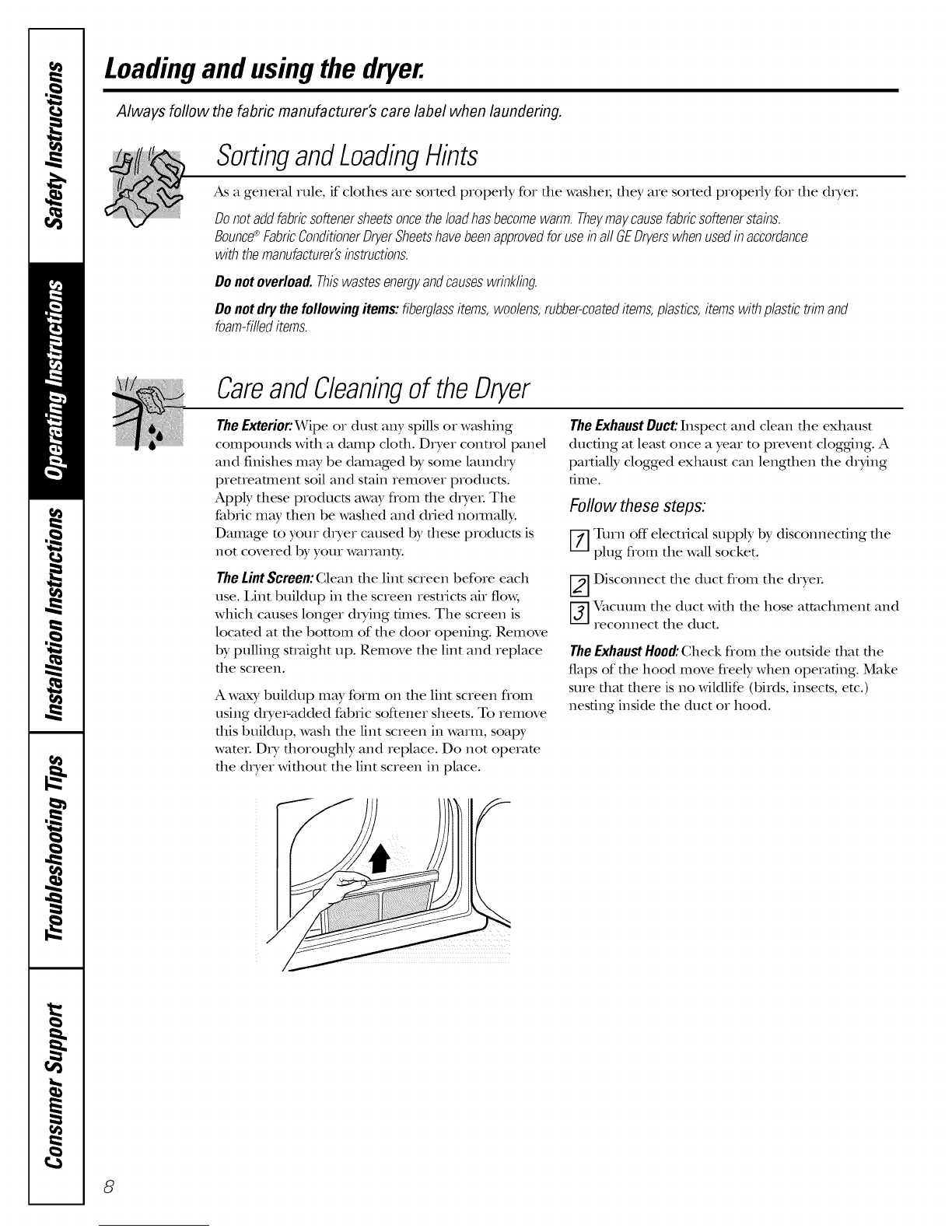
Cleanthelintfilterbeforeeachloadto prevent lint
accumulation inside the dryer or in the room.
DONOTOPERATETHEDRYERWITHOUTTHELINT
FILTERIN PLACE,UNLESSTHEDRYINGRACKISIN
USE.Ah,vays replace tile lint screen when finished
using the d_Ting rack.
• Do not dI y articles containing mbbeI, plastic
or similar mam_ials such as padded bins, mnnis
shoes, g_doshes, badl mats, rugs, bibs, baby pants,
plastic bags and pillows that may melt or burn.
Some rubber mamIials, when heated, can under
certain circumstances produce fire by
spontaneous combustion.
• Do not store plastic, paper or clodflng dmt may
burn or melt on top of the dxyer during
operation.
• Do not wash or dITarticles dmt have been
cleaned in, washed in, soaked in or spotted
with combustible or explosive substances (such _ts
wax, oil, paint, gasoline, degreaseIs, dry-cleaning
soNents, kerosene, etc.). These substances give
offvapots that m W igmim or explode. Do not add
these substances m the wash WamL Do not use or
place these substances around your washer or
d_Ter du_ing operation.
• Aalyarticle on which you have used a cleaning
sokent or dmt contains flammable mamrials
(such as cleaning cloths, mops, towels used in
beauty salons, restaurants or barber shops, etc.)
must not be placed in or near the d_Ter until
sokents or flammable materials have been
removed. There are many highly fl_umnable
imms used in homes such as acetone, denatured
alcohol, gasoline, kerosene, some household
cleaners, some spot removers, turpentines,
waxes, wax removers and products containing
peuoleum disfillams.
The laund_ T process can reduce die fl_une
remrdancy of fabrics. To avoid such a result,
careflfily follow the garment manufacturer's
care insu-ucfions.
• Garments labeled OrgAway from Hoator Do
Not Tumble Dry (such as life jackets containing
kapok) must not be put in your dryeL
• Do not dIT fiberglass articles in your dITeL
Skin iIxitafion could result flom the remaining
particles that may be picked up by clothing
du_ing subsequent d_Ter uses.
• To minimize file possibility of elecuic shock,
unplug ttlis appliance flom tile power supply
or disconnect the &yet at tile household
disuibufion panel by removing the fllse or
swimhing off the circuit breaker before
attemp6ng any maintenance or cleaning
(except the removal and cleaning of the lint
filter). NOTE: Turning the Cycle Selector knob
to an OFFposition does NOTdisconnect the
appliance from the power suppl?:
• Do not spray any type of aerosol into, on or near
d_Ter at any time.
• Do not place imms exposed to cooking oils in
your d_yer. Imms contaminamd with cooking oils
may conuibum to a chemical reaction that could
cause a clothes load m catch fire.

WARNING!
• Never attempt m operate dds appliance if
it is damaged, malflmcfioning, partially
dis_tssembled or has missing or broken parts,
including a damaged cord or plug.
• The interior of the machine and dae exhaust
duct connection inside the dryer should be
cleaned at least once a year by a qualified
mclmician. See the Loadingand Usingthe Dryer
section. Do not use any type of spIv_ycleaner
when cleaning diTer interioL Hazardous flmaes
or elecuical shock could OCCUL
• Ifyotns is a gas dryeI; it is equipped wifla an
automatic electric ignition and does not have a
pilot light. DONOTATTEMPTTOLIGHTWITHA
MATCH.Burns may result fiom having your hand
in the vicinity of the burner when the automatic
igmifion nnns on.
• You may wish to soften your laundered fabrics
oi reduce the smdc elecu_icity in them by using
a dIyer-applied fabric softener oi an antistatic
condifioneL We recommend you use ekher a
fabric softener in the x,v_tslacycle, according to the
manufacuner's insuucfions for those products,
or uy a dryer-added product for which the
manufacturer _ves wIJtten assurance on the
package that their product can be safely used in
your dryeL Service oi performance problems
caused by use of these products are the
responsibilit T of the manufacuners of those
products and are not covered under the wanmKy
m this appliance.
WHENNOTUSINGYOURDRYER
• Grasp the plug firmly when disconnecting dais
appliance to avoid damage m the cord while
pulling. Place the cord away flom mfffic areas so
it will not be stopped on, tripped over or
subjecmd m damage.
• Before discarding a diTei, oi removing it flom
service, remove the diyer door m prevent
children flom hiding inside.
• Do not tamperwida controls.
• Do not attempt to repair or replace any part of
this appliance oi attempt any servicing unless
specifically recommended in this Owner's Manual
oi in published user-repair insmlcfions that you
understand and have the skills to carry out.
READANDFOLLOWTHISSAFETYINFORMATIONCAREFULLY.
SAVETHESEINSTRUCTIONS
5

Aboutthe dryercontrolpanel
Models DPXH46 and DCXH46
FABRIC CARE WRINKLE CARE START
EXTENOED COOL AIR TUMBLE
PERM PRESS KNITS ]DEMCATES o. oR
iii
Models DSXH43, DH43 and PSXH43
FABRIC CARE CYCLE SIGNAL
PERM PRESS KNITS /DOICATES
c+,+..............++
START
TIMED DRY
miiiiiiii
rAe3 EASY CARE
e_RMe_ESS
;i _mCATES
iCOOLI:)owm
OPn_MORy
;o+CO+TO.S
0@Featuresandappearancemayvary.
6
ControlSettings
OFabric Care
COTI'0NS Forregulartoheawcottons.
REG.HEAT
PERM.PRESSForsynthetics,blendsanditemslabeledpermanentpressor tumbledrymediumheat.
MEDHEAT
KNITS/ Forknits,delicates,syntheticsanditemslabeledtumbledrylow heat.
DELICATES
LOWHEAT
AIRFLUFFForfluffingitemswithoutheat.UsetheTIMEDDRYcycle.
NOHEAT
ODrying Cycles
The COTTONS,EASYCAREand DELICATEScycles automatically sense fabric (hTness. Select MOREDRY
for heavier fabrics, LESSDRYfor lighter fabrics. The TIMEDDRYcycle will run for a selected dine.
COTTONSForcottonsandmostlinens.Formostloads,selecttile OptimumDrysetting(onsomemodels).
EASYCAREForwrinklefree,permanentpressanddelicateitems,andknits.Formostloads,selectthe
PERMPRESS OptimumDrysetting(onsomemodels).
DELICATESFordelicatesandspecialcarefabrics.Formostloads,selecttheOptimumDry
setting(onsomemodels).
TIMEDDRY SettheCycleSelectoratthedesireddryingtime.
oStart
Close the dryer dooL Select STARTOpening the door dtMng operation will stop the (hyeL To restart
the (hye_; close the door and select STARTto complete the cycle.

Aboutyourdryerfeatures.
Cycle Signal Option (on some models)
When the signal is on it will sound just five minutes as a reminder to remove
behnohorainhe
_/ you to remove tile clothes. Tile signal NOTE:
can be set at OFF (no sound), LOUD or
anywhere in between. • If items are removed before the end of
the cycle, turn the CYCLESELECTORknob
If ttle..dried load cannot be removed •Removet°OFF.
Ipromptly during the EASY CARE cycle,
the C) cle Selector will advance to the of the signaLgarmentSplacePr°mptlYclothesatonthehangersSOUnd
EXTENDED COOLDOWN setting. Unheated SOwrinkles won't set in.
tumbling continues during EXTENDED
COOLDOWN and WRINKLE CARE (on •Use the Cycle Signal especially when
some models) for 40 minutes to help drying fabrics like polyester knits and
reduce wrinkling. When die CYCLE permanent press. These fabrics should
be removed so wrinkles won't set in.
SIGNAL is on, it will sound briefly every
WRINKLE CARE
EXTENDEDC0 0LAIR TUMBLE
ON
ii
Wrinkle Care Option (on some models)
Use this option to minimize tile wrinkles
in clothes. It provides approximately 15
minutes of no-heat tumbling after tile
cloflles are d_y.
This option can only be used with the EASY
CAREand DELICATEScycles.
Replacing the Dryer Light Bulb (on some models)
AWARNING: reducetile
risk of electric shock, disconnect fllis
appliance flom file power supply
before attempting any user
mainmnance. Turning the controls
m the OFFposifion does not
disconnect this appliance flom the
power supply.
The dryer light is locamd above the dryer
door opening.
Before replacing the light bulb, be sure m
unplug the dryer power cord or disconnect
tile dcyer at tile household distribution
panel by removing tile fllse or switching
off tile circuit breakeL
Toreplacethe dryerlight:
[--_ Using a small fiat blade screwdriver,
pry tile t)ottom of tile light cover out
and off tile light housing.
[_-] Unscrew tile bulb when cool and
replace it with an appliance bulb of
tile same or lower wattage.
V_] Snap the light cover back on tile light
housing.
Drying Rack (on some models)
A handy drying rack may be used for drying
articles such as smff_d toys, pillows or
washable sweaters.
[_] Remove tile lint screen.
[_--]Place tile flont bar under tile lip of tile
lint screen opening.
[j] _qlen items are dD,, remove tile rack
and replace the lint screen. DONor
OPERATETHEDRYERWITHOUTTHEtINT
SCREENIN PLACEUNLESSTHEDRYING
RACKISIN PLACE.
NOTE:
•Tile dxying rack must be used Mill file
TIMEDDRY cycle.
•Do not use this d_ying rack when there
are other clothes in tile d_yeL
7

Loadingand usingthe dryer.
Always follow the fabric manufacturer's care label when laundering.
SortingandLoadingHints
As a general rule, if clothes are sorted properly for the washer, they are sorted properly for the dryeL
Donotaddfabricsoftenersheetsoncetheloadhasbecomewarm.Theymaycausefabricsoftenerstains.
Bounce®FabricConditionerDryerSheetshavebeenapprovedforuseinall GEDryerswhenusedinaccordance
withthemanufacturer'sinstructions.
Donotoverload.Thiswastesenergyandcauseswrinkling.
Donotdrythefollowingitems:fiberglassitems,woolens,rubber-coateditems,plastics,itemswithplastictrimand
foam-filleditems.
CareandCleaningof theDryer
TheExterior:Wipe or dust any spills or washing
compounds with a damp cloth. Dryer control panel
and finishes may be damaged by some laundry
pretreatment soil and stain remover products.
Apply these products away from the d_yeL The
fabric may then be washed and d_ied nommlly.
Damage to your d_yer caused by these products is
not covered by your warmnb,:
The LintScreen: Clean file lint screen before each
use. Lint buildup in the screen restricts air flow,
which causes longer diTing times. The screen is
locamd at the bottom of the door opening. Remove
by pulling straight up. Remove the lint and replace
the screen.
A waxy buildup may form on file lint screen flom
using dITer-added fabdc softener sheets. To remove
this buildup, wash the lint screen in warm, soapy
water. DtT thoroughly and replace. Do not operam
the d_Ter without the lint screen in place.
TheExhaust Duct:Inspect and clean the exhaust
ducting at least once a year to prevent cloggdng. A
partially clogged exhaust can lengthen the drying
time.
Follow these steps:
[7] urn off electrical supply by disconnecting the
plug from the wall socket.
[_-] Disconnect the duct flom the dryeL
[j] acuum the duct with the hose attachment and
reconnect the duct.
TheExhaustHood:Check flom the outside that the
flaps of the hood move freely when operating. Make
sure that there is no wildlife (birds, insects, etc.)
nesting inside the duct or hood.
8

Installation
Instructions Spacemaker Dryer
DCXH46,DSXH43D,DPXH46,DH43,PSXH43
ffyouhaveanyquestions,in theU.S.,ca//800.0£ CARES(800.432.2737)orvisitour Website at:
GEAppliances.com.InCanada,ca//1.800.561.33440rvisitourWebsiteat:www.GEAppliances.ca
BEFORE YOU BEGIN
Read these instructions completely and carefully.
•IMPORTANT - S},vethese
instructions for local inspector's use.
•IMPORTANT - Obse,, e
governing codes and ordinances.
• Note to Installer -Be sure to leave these
instructions with the Gonsumer.
• Note to Consumer - Keep these instructions
for fi_ture reference.
•Sldll level -Installation of tiffs appliance requires
basic mechanical and electrical skills.
• Completion time - 1-3 hours
• Proper installation is the responsibility of the
installm.
•Product failure due to improper installation is not
covered under the _rarranty.
• Remove and discard existing plastic or metal foil
duct and replace with UL-listed duct.
IN THE COMMONWEALTH OF
MASSACHUSETTS
• This product must be installed by a licensed
plumber or gas fitter
• When using ball-type gas shut-off valves, they
shall be the T-handle type.
• A flexible gas connector, when used, must not
exceed 3 feet.
CALIFORNIA SAFE DRINKING WATER
AND TOXIC ENFORCEMENT ACT
This act requires the governor of California to publish
a list of substances known t0 the state t0 cause cance_,
birth defects or other reproductive harm and requires
businesses to warn customers of potential exposure to
such substances. (;as appliances can cause minor
exposure to four of these substances, namely benzene,
carbon monoxide, formaldehyde and soot, caused
primarily by the incomplete combustion of natural
gas or LP feels. Properly adjusted dryers will minimize
incomplete combustion. Exposure to these substances
can be minimized further by properly venting the
dryer to the outdoors.
FOR YOUR SAFETY:
WARNING
• To reduce file risk of severe iqju_T or dead1, follow all
installation insuucfions.
• Clothes d_yer installation must be perfomled by a
qualified insmlleL
• Install the clothes d_yer according to these insnucfions
and in accordance with local codes.
• This d_yer illust be exhausmd m the outdooi_.
• Use only 4" rigid metal ducfing for exhausting the
clothes d_yer m the outdoors.
• DO NOT install a clothes &yet with flexible plastic
ducfing materials. If flexible metal (semi-rigid or foil-
type) duct is installed, it must be UIAismd and installed
in accordance with the insnucfions found in
"Connecting the Diyer m House Vent" on page 12 of
this manual. Flexible ducfing mamrials are known m
collapse, be easily crushed, and nap lint. These
conditions will obsn-uct d_yer airflow and increase the
risk of fire.
• Do not install or store this appliance in any location
where it could be exposed m wamr and/or weatheL
• Save these insn-ucfions. (Installers: Be sure to leave
these insnucfions with the cusmmeL)
• The National Fuel Gas code resnicts installations of
gas appliances in ga_wges. They must be 18" (45.7 cm)
off"the ground and protecmd flom vehicles by a
barrieL See Locationof YourDryersection.
• The electrical service to the &yet must conform with
local codes and ordinances and the latest edition of the
National Electrical Code, ANSI/NFPA 70 or in Canada,
CSA C22.1 Canadian Electrical Code Part 1.
• The gas service to the duet must conform with local
codes and ordinances or the lamst edition of the
National Fuel Gas Code ANSI Z223.1 or in Canada,
CAN/CGA B149.12. The gas dIyer is designed under
ANSI Z 21.5.1 or ANSI/UL2158-(_N/CSA C22.2
(latest editions) for home use only. This dryer is not
recommended for commercial applications such _ts
restatmmts or beauty salons.
9

Installation Instructions
TOOLS AND MATERIALS
YOU WILL NEED
[_] Phillips head screwdriver
[_]Adjustable pliers (adjust leveling legs)
[_] Gaxt)enter's level
[_] Flat or smfight blade screwdrNer (mW be needed
for cord smfin relief)
Duct tape
[_] Rigid or UL-listed flexible metal 4" (10.2 cm) duct
[_]Vent hood
[_] 1/4" nut drNer (remove temdnal block access
cover and instaU cord) (ELECTRIC DRYER)
[_] Pipe thread sealer (GAS DRYER)
[_] UIAismd smfin relief (may be supplied
with cord)
[_] UIAisted 30A, 240V, ,%wire,#10 AWG minimum
conductor power cord (U.S. existing su-ucmre)
[_] UIAismd 30A, 240V, 4-wire, #10 AWG
minimum conductor power cord is required
(U.S. new consuucfion)
[_] Flexible stainless smel or plas6c-coated brass
commecdng robe (if allowed by building code)
(GAS DRYER)
[_] Open-end wrenches for flexible robe and
connector (GAS DRYER)
PREPARING THE INSTALLATION SITE
AND UNPACKING YOUR DRYER
1°
°
3°
Prepare die area and exhaust for inst_dlafion
of die new dxyeL
Check to be sure that die existing exmmal
exhaust is clean and fllat it meets attached
installation specifications.
Place die four corner posts flom die shipping
carton on die floox; parallel m each otbex; 2-3"
apart. Carefidly 1Wdie dxyer on its left side on
mp of die comer posts. Remove the foam
shipping pad.
CAUTION: io prevent damage, do
not use die control panel as a means m pick up
or move die dxyeL
Foamshippingpad
4. Remm file dxyer m an upright position.
5. Move die dxyer m die desired location.
6. Connect die exmmal exhaust.
7. Adjust die leveling legs to match the washer
height. The dryer must be level and rest fimdy
on all four leveling legs.
8. Connect the power supply.
9. Check die operation of die power supply and
venting.
10. Place file (_,vner's ManuM and file Installation
Instructions in a location where they Mll be
noticed by file owneL
10

Installation Instructions
Read these instructions completely and carefully.
ELECTRICAL CONNECTION
INFORMATION FOR
ELECTRIC DRYERS
A_ WARNING- Io,e_l.ce_t,e,i_kof
fire, electric shock or personal i_jury:
• DO NOT USE AN EXTENSION CORD WITH
THIS APPLIANCE.
•THIS APPLIANCE MUST BE PROPERLY
GROUNDED.
This dryer must be electrically grounded in accordance
with local codes and ordinances, or in the absence of local
codes, in accordance with the NATIONAL ELECTRICAL
CODE, ANSI/NFPA NO. 70 or in Canada CSA C22.1
Canadian Electrical Code Part 1.
Electrical Requirements
• This dryer must be connected to a 208V or 240V
indMdual branch circuit, protected by 30-amp circuit
breakers or time-.delay fllses.
• Power supply: 3-wire 240wolt, single-.phase, 60-Hz,
Alternating Current. (Canada-240 volt, single-phase,
60-Hz Alternating Current.)
• Use copper conductors only.
• If the electric supply does not meet the above
specifications, call a licensed electrician.
NOTE: A wiring diagaam is located under the top panel.
11
ELECTRICAL CONNECTION
INFORMATION FOR GAS DRYERS
A_WARNING- To_e_l.c__heriskof
fire, electric shock or personal ii_jury:
• DO NOT USE AN EXTENSION CORD OR AN
ADAPTER PLUG WITH THIS APPLIANCE.
•DO NOT, UNDER ANY CIRCUMSTANCES, CUT OR
REMOVE THE THIRD GROUNDING PRONG FROM
THE POWER CORD.
This dryer must be electrically grounded in accordance
with local codes and ordinances, or in the absence of local
codes, in accordance with the NATIONAL ELECTRICAL
CODE, ANSI/NFPA NO. 70 or in Canada, CSA C22.1
Canadian Electrical Code Part 1.
Electrical Requirements
• This d_yer must be supplied with 120V, 60-Hz,
and connecmd m a properly grounded branch
circuit, protected by a 15- or 20-amp circuit breaker
or time-delay flase.
• If the electric supply provided does not meet the
above specifications, it is recommended that a licensed
electrician install an approved outlet.
External Ground (if required)
Ensureproperground
existsbeforeuse
An external ground wire (not provided), which meets local
codes, may be added by attaching it to the green ground
screw on the rear of the dryer in the upper left corner
above the cord, and to grounded metal cold water pipe or
other established ground.
L-
Attachgroundwire
(obtainlocally)
NOTE: A wMng diagrmn is located under the top panel.

Installation Instructions
EXHAUST SYSTEM CHECKLIST
HOOD OR WALL CAP
• Terminate in amanner to prevent back drafts or ent W
of birds or other wildlifb.
• Termination should present minimal resistance to
the exhaust airflow and should require little or no
maintenance to prevent clogging.
• Never install a screen in or over the exhaust duct.
• Wall caps must be installed at least 12" above ground
level or any other obstruction with the opening
pointed down.
SEPARATION OF TURNS
• For best performance, separate all turns by at least
4 ft. of straight duct, including distance between last
mrn and dampened wall cap.
SEALING OF JOINTS
• All joints should be tight to avoid leaks. The male end
of each section of duct must point away fl'om the dryer.
• Do not assemble tile ductwork with fasteners that
extend into the duct. They will serve as a collection
point for lint.
• Duct joints should be made air- and moisture-tight
by wrapping the overlapped joints with duct tape
or aluminum tape.
• Horizontal r/lilS should slope down towards the
O/ltdoors 1/4" pet" foot.
INSULATION
• Ductwork that runs fllrough an unheated area or is
near air conditioning should be insulated to reduce
condensation and lint buildup.
Correct
Incorrect
Don_
WARNING To reduce the risk of fire
or personal injury:
• This cloflles dD,er must be exhausted to file outdoors.
• Use only 4" rigid metal ducfing for tile home exhaust
duct.
• Use only 4" rigid metal or UIAisted flexiNe metal (semi-
rigid or foil-t),pe) duct m commct tile d_yer m tile home
exhaust duct. It must be installed in accordance wifll the
insnucfions found in "Connecting Tile D_yer To House
Vent" on this page.
• Do not mmfinam exhaust in a chimney, a wall, a ceiling,
gas vent, crmd space, attic, under an enclosed floo_; or
in any other concealed space of a building. 12
Jk WARNING
• Never mmfinate file exhaust into a common duct
with a kitchen exhaust system. A combination of
grease and lint creams a pomnfial fire hazard.
• Do not use duct longer that specified in tile exhaust
length table. Longer ducts can accumulate lint,
creating a potential fire hazard.
• Never install a screen in or over tile exhaust duct.
This will cause lint m accumulate, creating a pomnfial
fire hazard.
• Do not assemble ductwork with any fasmneI5 that
exmnd into tile duct. These fasmners can accumulam
lint, creating a pomnfial fire halard.
• Do not obstruct incoming or exhausted all
• Provide an access for inspection and cleaning of tile
exhaust sysmm, especially at turns and joints. Exhaust
system shall be inspecmd and cleaned at least once
a yeaL
CONNECTING THE DRYER TO
HOUSE VENT
RIGID METAL TRANSITION DUCT
• For best drying performance, a rigid metal transition
duct is recommended.
• Rigid metal transition ducts reduce tile risk of
crushing and kinking.
UL-LISTED FLEXIBLEMETAL (SEMI-RIGID)
TRANSITION DUCT
• If rigid metal duct cannot be used, then UL-listed
flexible metal (semi-rigid) ducting can be used
(Kit X_X08X10077).
• Never install flexible metal duct in walls, ceilings,
floors or other enclosed spaces.
• Total length of flexible metal duct should not exceed
8 feet (2.4 m).
• For many applications, installing elbows at both
the dryer and the wall is highly recommended
(see illustrations at left). Elbows allow the dryer to
sit close to the wall without kinking and/or crushing
the transition duct, maximizing dwing performance.
• Avoid resting the duct on sharp objects.
UL-LISTED FLEXIBLEMETAL (FOIL-TYPE)
TRANSITION DUCT
• In special installations, it may be necessary to connect
the dryer to the house vent using a flexible metal
(foil-type) duct. A UL-listed flexible metal (foil-type)
duct may be used ONEY in installations where rigid
metal or flexible metal (semi-rigid) ducting cannot
be used AND where a 4" diameter can be maintained
throughout the entire length of the transition duct.
• In Canada and the United States, only the flexible
metal (foil-type) ducts that comply with the "Outline
for Clothes Dryer Transition Duct Subject 2158A"
shall be used.

Installation Instructions
CONNECTING THE DRYER TO
HOUSE VENT (CONT.)
• Never install flexible metal duct in walls, ceilings,
floors or odler enclosed spaces.
• Total lengdl of flexible metal duct should not
exceed 8 feet (2.4 m).
• Avoid resting tlle duct on sharp objects.
• For best diTing performance:
1. Slide one end of the duct over the clodles
dryer outlet pipe.
2. Secure the duct witll a clamp.
3. Witll the dryer in its permanent position,
extend the duct to its fldl lengdl. Allow 2" of
duct to overlap tlle exhaust pipe. Cut off and
remove excess duct. Keep tl_e duct as straight
as possible for maximum airflow.
4. Secure the duct to the exhaust pipe with
the odler clamp.
EXHAUST DIRECTION
All (liTers are shipped set up for rear exhausting.
On elecuic d_yers, exhausting can be on the cabinet fight
or left side, or through the dryer bottom. G;ts dryeis can
exhaust on the cabinet fight side or the d_yer bottom. To
change exhaust direction you will need Exhaust Kit Pub.
No. 14-A018 and a rigid metal 4" 90-degree elbow. The kit
is available ttuough your GE remileL Follow the
insmlcdons supplied with the kit.
Same as EXHAUST DUCT LOCATING
€other side DIMENSIONS
5 7/8"
115cm)
135/16"
•. (34cm)
4 3/8"
(11cm)
3 3/4" 3 3/4" (9.5 cm)
EXHAUST DUCTING LENGTH
The exhaust system should be inspected and cleaned a
minimum of eve Uyear widl nomml usage. The more tile
d_yer is used, tlle more often you should check tile exhaust
system and vent hood for proper operation.
•DO NOT assemble the duct work with fasteners that
exmnd into the duct. They will serve as collection points
for lint.
• Insulation - Ductwork which runs through an unheamd
area or is near an air conditioning duct should be
insulated to reduce condensation and lint buildup.
MAXIMUM LENGTH
of4"(10.2cm)Dia.RIGIDMETALDUCT
PREFERREDVENTHOODTYPE
4" (10.2cm) Louvered
Number
of 90°
.2,5"
_. L
era)I_
0 60"(18,28m) 48" (14,63m)
1 52"(15,84m) 40" (12,19m)
2 44"{13,41m) 32" {9,75m)
3 32"(9.75m) 24" (7.31m)
4 28"(8.53m) 16" (4.87m)
INSTALLMALE FITTINGSIN CORRECTDIRECTION
GAS SUPPLY REQUIREMENTS
Replace brassconnecting pipe that is not plastic-coated.
Stainless smel or plasfic-coamd brass MUST be used.
WARNING: Neve,','e.seoldflexible
connectors. The use of old flexible connectors can cause
gas leaks and personal injm3_ Always use NEW flexible
connectors \allen installing a gas appliance.
1°
°
3°
4°
Installation MUST conform wifll local codes, or in the
absence of local codes, with the National Fuel Gas
(]ode, ANSI Z223.1 (lamst edition) or in Canada, the
current CAN/CGA B149.
The gas supply line should be of i/2" (:l.27 cm) rigid
pipe.
If codes allow, flexible metal robing may be used
m connect your diyer m the gas supply line. The
robing MUST be consmlcmd of stainless smel or
plasfic-coamd brass.
The gas supply line MUST have an indMdual stmtoff
valve.
_°
6°
°
A 1/8" (0.32 cm) NPT plugged tapping, accessible for
rest gauge connection, MUST be installed immediately
upsUeam of the gas supply comlecfion to the d_yeL
The dryer MUST be discomlecmd flom die gas supply
piping sysmm during any pressure resting of the gas
supply piping sysmm at rest pressures in excess of 1/2
psig (3.45 kPa).
The d_yer MUST be isolamd flom die gas supply piping
system during any pressure resting of the gas supply
piping system at test pressures equal to or less than
1/2 psig (3.45 kPa).
13

Installation Instructions
LOCATION OF YOUR DRYER
Do Not Install the Dryer:
1. Do not install the dryer in an area exposed to dripping
water or outside weather conditions.
2. Do not install the dryer in an area where it will come
in contact with curtains, drapes or anything that will
obstruct the flow of combustion and ventilation ai_.
3. Do not install the dryer on carpet.
Floor MUST be solid with a maximum slope
of 1" (2.54 cm).
Undercounter Installation:
If an undercounmr* installation is desired, die dater
MUST have a top sheet kit installed, Pub. No. 14-A008.
Kit is available through your GE retailea.
*Custom-sizedcountertopis required.
Installation in Recess or Closet:
1.This dryer MUST be exhausted outdoors.
2. No other tirol burning appliance shall be installed in the
same closet as the GAS DRYER.
3.Your dryer needs the space around it for proper
ventilation. DO NOT INSTALL YOUR DRYER IN A
CLOSET WITH A SOLID DOOR.
4. Gloset doors must be louvered or otherwise venfilamd
and must contain a minimum of 60 sq. in. of open area
equally disuibumd. If the closet contains both a washer
and a daTea, doors must contain a minimum of 120 sq.
in. of open area equally disuibumd. Air openings are
required to be unobsuucmd when a door is installed.
A louvered door with equivalent air openings for the flail
length of the door is acceptable.
0
Closet door
in.
(7.6cm)
60sq.in.
(387.1sq.cm)
60sq.in.
(387.1sq.cm)
3in.
[7.6cm)
Allow thefollowingclearancesforeaseofinstallation:
FRONT SIDES REAR TOP
Alcove,stack, 3"(7.6cm) 0(0cm) 3"(7.6cm) 0(0cm)
undercounter
orcloset
THIS DRYER MUST BE EXHAUSTED OUTDOORS.
5. The following illustrations show minimum clearance
dilnensions for proper opeavtfion in a recess or closet
installation.
ii
..._ 114. O"
(Ocm)
II
" 3.... 3"
.=) I1(._ ._) II (,.
" (7.6cm) " (7.6cm)
II II
II II
STACKED INSTALLATION
If a stacked w_her/dryer installation isdesired, )ou MUST
use Stacking KitWE25X10020. This kit is available through
your GE retailer
14

Installation Instructions
MOBILE HOME INSTALLATION
1. DIyer MUST be exhausted outside (outdoors, not
beneath the mobile home) using metal ducfing fllat will
not support combustion. Metal ducfing must be 4"
(10.16 cm) in diameter wifll no obstructions. Rigdd metal
duct is preferred.
2. If die d_Ter is exhausmd dlrough the floo_, file exhaust
sysmm MUST NOT mmlinam beneath the mobile
home. Termination MUST be securely fasmned to the
mobile home su_ucmre.
3. When installing a gas d_yer into a mobile home, a
provision must be made for outside make-up all This
provision is m be not less than twice the area of the d_yer
exhaust outlet.
4. Gas dryers MUST be fastened to the floor using Mobile
Home Installation Kit Pub. No. 14-D346-33.
5. See the Exhaust System Checklist section for other
important venting information.
6. Installation MUST conform to current Manufactured
Home Gonsmlcfion & SafetTyStandard (which is a
Federal Regulation Title 24 GFR--Part 32-80) oI,
when such standard is not applicable, with American
National Standard for Mobile Homes, ANSI/NFPA No.
501B. In Canada, the CSA Z240 is applicable.
Don't
Correct
Incorrect
Thedryeris designedunderANSlZ21.5.1.
ROUGH-IN DIMENSIONS
1
267/8" "_1
(68.3cm)
Electricalconnection
j
33/4"
(9.5cm)
29/16" ,
139/16" (6.5cm7"-_"
(34.5cm)_(_
3/16" (0.48cm)Dia.
gas poe
REARVIEW
!
Under
counter
345/8"
(87.9cm)
36"
(91.6cm)
!
<
I
3/4"
(1.9cm)
Dooropen
90°
471/2"
(120.7cm)
43/8"
(11.1cml""_ I
0ptiona4.-,.,_" ,
vent knockout '-
253/4"
(65.4cm)
SIDEVIEW
4<----
!
m1'
33/4"
(9.5cm)
SERVICING - Consideration must be given to provide
adequate clearances for installation and servicing.
15

Installation Instructions
ELECTRICAL INSTALLATION FOR
ELECTRIC DRYERS
WARNING: Thefollow .gspec c
requirements for proper and safe elecuical installation of
your dIyeL Failure to follow these instructions can cream
elecuical shock and/or a fire hazard.
This appliance MUST be properly grounded.
Elecnical shock can result if the dIyer is not properly
g_ounded. Follow the insu_ucfions in tiffs manual for proper
grounding.
DO NOT use an exmnsion cord wifla dais dIyeL Some
exmnsion cords are not designed m withstand the amounts
of elecn-ical current this diyer utilizes and can melt,
creating elecu-ical shock and/or fire hazard. I,ocam the
diyer within reach of the wall outlet, taking into account
the length of power cord m be purch;ksed and allowing
some slack in the cord. Refer m ElectricalRequirementsin
this manual for the proper power cord m be purchased.
A UIAismd strain relief must be installed Ohm power cord.
If the strain relief is not attached, the cord can be pulled
out of the dIyer and can be cut by any movement of the
cord, resulting in elecn-ical shock.
NOTE: DIyers operating on 208welt power supply will
have longer diTing times than those operating
on 240-volt power supply.
A wiring diagq-amis located under the mp pmael.
GROUNDING REQUIREMENTS
_/kWARNING: Improper coianection of the
equipment%_ounding conductor can result in a risk of
electric shock. Check wifla a licensed electrician if you are in
doubt as to wheflaer die appliance is properly gnounded.
The diyer MUST be grounded. In die event of a
malfunction or breakdown, grounding will reduce the risk
of elecu-ical shock by creating a path of least resistance for
electrical current.
Grounding must be in accordance with local codes and
ordinances, or in the absence of local codes, in accordance
with the National Elecu-ical Code ANSI/NFPA No. 70.
For agrounded, cord-connected electric dryer."
If your diyer is equipped wifla a power supply cord having
an equipment-grounding conductor and a grounding
plug, the plug MUST be plugged into an appropriate,
copper-wired receptacle (in the U.S.), or in Canada, an
appropriam oudet that is properly installed and grounded
in accordance with all local codes and ordinances, flirt
doubt,calla licensedelectrician.
For apermanently connected electric dryer."
• The dITer MUST be connecmd m a grounded metal,
pemaanent wiring sysmm; or an equipment-g_ounding
conductor iaatlst be i-un with the circuit conductois and
colmecmd m the equipment-grounding mmfinal or lead
on the appliance.
For a grounded, cord_onnected gas dryer."
• This dIyer is equipped wifla a flnee-prong (grounding)
plug for your promcfion against shock hazard and should
be plugged direcdy into a properly grounded three-prong
receptacle. Do not cut or remove the grounding prong
flom this plug. Do not modify the plug on this appliance.
If it will not fit the oudet, have a proper oudet installed by
a qualified elecu-ician.
16

Installation Instructions
3-WIRE SYSTEM FOR
ELECTRIC DRYERS
NOT for use in Canada.
DO NOT use for Mobile Home Installations.
NOT for use on new construction.
1. Remove the screws securing the terminal block access
cover and the strain relief mounting bracket located on
the back of the dryer upper cornet.
2. Install a UL-listed suMn relief into the power cord ent D,
hole of the mounting bracket. Finger-tighten the nut
only at tiffs time.
Greengroundscrew Silverterminal
Greenneutral
groundwire Tightennutto
threads
IUsecopper
conductorsonly. elief
mountingbracket
3. Thread a UIAisted 30A, 240V, 3 #10 AWG mininmnl
copper conductor power cord through the strain relief.
4. Attach the power cord neutral (center wire) conductor
to the silver-colored center terminal on the terminal
block. Tighten the screw securel):
5. Attach the remaining two power cord outer conductors
to the outer brass-colored temfinals on the temfinal
block. Tighten both screws securely.
-& WARNING: Donotmake.st,a,pbe,,do,
crimp wiring/conductor at connections.
6. Reatmch the strain relief mounting bracket to the
back of the dryer with screws provided. Tighten screws
securel):
7. Tighten the screws securing the cord resuaint firefly
against the power cord.
8. Tighten the strain relief nut securely so that the strain
relief does not arm.
9. Reinstall the terminal block access covet.
4-WIRE SYSTEM FOR
ELECTRIC DRYERS
Effective January 1, 1996: The National ElecuJcal (;ode
requires that new construction (non existing) utilize a
4-wire connection to an electric @yet.
In Canada a 4-wire power supply cord is installed on
the dryer.
1. Remove the screws securing the mrminal block access
cover and the suain relief mounting bracket located on
the back of the dryer tappet cornet.
2. Install a UIAisted smdn relief in the enu T hole of
the mounting bracket. Finger-figbmn the nut only
at this time.
Remove the green neutral ground wire flom the green
ground screw located above the terminal block.
3.
Typical4
c0nduct0r/| - I_
receptacle_
Black240V
Typical n. .
4 conductorcordZ_ WBte neutral
1.1
g- _ Red240V
_,'_Greenground
4. Thread a UIAisted 30A, 240V,4 #10 AWG minimum
copper conductor power cord through the smfin relief.
5. Attach the green power cord ground wire m the
cabinet with the green ground screw.
6. Attach the whim (neumfl) power cord conductor flom
the power cord and the green ground wire flom the
@yer harness to the siker-colored cenmr terminal on
the terminal block. Tigbmn the screw securely.
7. Attach the red and black power cord conductors to the
oumr bins>colored mrminals on the mmfinal block.
Green roundwire
Greenground
screw Silverterminal
Greenneutral
groundwire
block
Black
Nut lighten nutto
threads
mounting
bracket
AWARNIN' t.: Do,,otm.ke.st,-tVbe,,d
or crimp wMng/conductor at d_econnections.
8. Tighten the screws securing the cord restraint firmly
against the power cord.
9. Tigbmn the smfin relief nut securely so the smfin relief
does not turn.
10. Reinstall the mrminal block access covet.
17

Installation Instructions
GAS CONNECTION FOR
GAS DRYERS
1. Remove the shipping cap fiom gas pipe at the rear of
the dryeL
Conversion to LP Gas: DO NOT connect file d_Ter to
I,P gas service wifllout converting file gas valve. An LP
conversion kit (Pub. No. 14-A038) MUST be inst_dled
by a qualified gas mchnician.
a. Connect a 1/2" (1.27 cm) I.D. semi-rigid
or approved pipe flom g_s supply line m
the ,3/8" (0.96 cm) pipe located on the back of the
dryeL Use a 1/2" m 3/8" (1.27 cmm 0.96 cm)
reducer for a connection. Apply an approved thread
sealer that is resistant m the corrosive action of
liquefied gases on all pipe connections.
b. Open the stmtoffvalve in the gas supply line.
c. Test all connections by brushing on a soap), water
solution.
WARNING: NEVERTEST
FOR GAS LEAKS WITH AN
OPEN FLAME.
2. Connect the exhaust duct to outside exhaust system.
Use duct rope to seal all joints.
3, X_rifllfile d_Ter in its finM position, adjust one or more
of file legs until tim dryer is resting solidly on M1four
legs. Place a level on top of file dryeL THE DRYER
MUST BE LEVEL AND RESTING SOLIDLY ON
ALL FOUR LEGS.
4. Plug the power cord into a grounded outlet.
NOTE: Check to ensure the power is off at circuit
breaker/fllse box before plugging the power cord
into the outlet.
5. Turn on the power at the circuit breaker/filse box.
CAUTION: Befo,eop. .i.gthed,),e,;
make sure the dryer area is clear and flee flom
combustible materials, gasoline, and other flammable
vapo,s. Also see that nothing (such _tsboxes,
clothing, etc.) obsuucts the flow of combustion and
ventilation all
6. Run the dD,er through a cycle check for proper
operation.
NOTE: On gas &yers, before file burner Mll light, it is
necessa_y for the gas line m be bled of all If the burner
does not light within 45 seconds the first time the d_yer is
turned on, the saferT switch will shut the burner off: If this
happens, mrn the timer m OFF and wait 5 minums before
making another attempt to light.
7. If your dD,er does not operate, ple_tse review the
Troubleshooting 77pssection in tiffs manual before
calling for service.
8. Place these instructions in a location near the dD,er for
din]re reference.
18

Stacking Instructions
WARNING:
• To reduce file risk of electric shock, disconnect fllis
appliance flom the power supply before attempting
any tlseI illaintenance. Turning file conuols to the
OFF position does not disconnect this appliance
flom the power supply.
• Refer m die washer and dITer installation insuucfions
prior m stocking appliances. Reading all of tile
information contained in these insmlcfions will simplify
the installation and ensure a correct and sJe operation.
A fire hazard and/or personal i_,jtnTcould result flom
improper installation.
TOOLS REQUIRED FOR STACKING
THE DRYER
• Phillips head screwdriver
• Ghannelqock adjustable pliers
MOUNTING THE DRYER TO
THE WASHER
Thenumbers in the illustration correspond to steps.
1. Remove file washer mp panel by first removing file 4
screws in die 2brackets located on die top rear of die
washeI;
Slide the mp forward, lift die flont of die top up and
remove the mp panel.
Remove die 2brackets flora die rear of die top panel.
2. Using file 4 screws fllat were removed in stop 1, install
die brackets in die rear support as shown.
3. Remove die 4 screws and die 2 long flont brackets
located on die top flont of die washeL
4. Install die 2new flont mounting brackets provided and
the 4 screws that were removed in stop 3. Nora that the
tab of the flont mounting bracket is facing forward as
shown in the illusm_fion.
19

Stacking Instructions-Reversing Door Swing
Thenumbers in the illustration correspond to steps.
5. Using file blade end of a put b, knife covered with
masking tape, careflllly remove file hole plugs located
in the bottom of the d_Ter flont panel.
6. Remove the 4 legs flom the d_yer base.
7. Place the d_Ter on mp of the washeL Slide the dryer
back into the rear brackets (7A) then drop the flont
down over the flont b_vmkets (7B).
®
@
/
2
8. Insert the 2 long screws provided in file kit flnough
the holes in the dryer fiont panel and inst_dl into the
flont mounting b_ckets.
9. Install file hole plugs removed in stop 5.
10. Refer m die washer and d_yer installation insmlcdons
for proper installation and flmcfion.
11. S_wefile top panel and b_ackets in file case offlmne
sided)y-side use.
REVERSING THE DRYER
DOOR SWING
1. Open the d_yer dooL Remove the 4 hinge hole plugs or
screws flom the left side of door opening. Place nearby
for fimlre installation. NOTE: Youmayneed aplastic knife
to helppull out theplugs. Be carefulnot toscratch thepaint.
2.Remove the four screws fllat secure file door hinges m
the dIyer flont panel. NOTE: RemoveIscrew from each
of the2hingesfirst. Holdthe doorfirmly beforeremovingthe
last 2screws.
3.Romm file door 180° and reinstall file door hinges m file
d_Ter flont panel with the 4 screws.
4. Install file 4 hinge hole plugs or screws fllat were
removed in stop 1 into the open screw holes on the _ight
side of the door opening.
Remove4screws--onefromeachhingefirst
20
Other manuals for Spacemaker DSXH43
2
This manual suits for next models
4
Table of contents
Other GE Dryer manuals
Popular Dryer manuals by other brands

Bosch
Bosch WTW84160GB Installation Instructions, Instructions for Use, Programme... instruction manual

Whirlpool
Whirlpool W10388775A installation instructions

Frigidaire
Frigidaire FASG7021NW uso y cuidado

Parker
Parker SPE026-ES user manual

Haier
Haier HDHP80E1 user manual

Elan
Elan ElanDRYER XXL user guide

AEG
AEG LAVATHERM 55800 User information

Kenmore
Kenmore 9791 - 27 in. Laundry Center operating instructions

LG
LG DLHX4072 series owner's manual

General Technomatic
General Technomatic DGX-999 user manual

Crosley
Crosley 134539400 (0503 operating instructions

American Dryer Corp.
American Dryer Corp. Dyer AD-26 parts manual