GE
Lumination
Installation Guide
12
Volt
6
7
8
9
1
2
3
4
5
UL approved 18 AWG (0.82 mm2) supply wire
UL approved 22-14 AWG (0.33-2.08 mm2)
wire connectors or 22-18 AWG
(0.33-0.82 mm2) in-line/IDC connectors
#6 or #8 (M3 or M4) screws or 1/8 inch
(3.2 mm) rivets
End caps (GETMEC1)
Tetra®Power Supply (GEPS12-20,
GEPS12-60, GEPS12-60U)
Tetra®PowerStrip LED modules
(GEWHSSP3-65K, GEWWSSP3-41K)
Components
imagination at work
Tetra®PowerStrip
LED Lighting System
6180 Halle Drive • Valley View, Ohio 44125-4635 • USA
P: 216.606.6555 • F: 216.606.6599 • www.led.com • info@led.com
Lumination, LLC is a subsidiary of the General Electric Company. Tetra is a trademark of Lumination, LLC. The GE brand, logo, and ecomagination are trademarks of the General Electric Company.
© 2009 Lumination, LLC. Information provided is subject to change without notice. All values are design or typical values when measured under laboratory conditions.
SIGN066-R060909
For customer service & technical support, contact:
1-888-MY-GE-LED (1.888.694.3533)
(GEWHSSP3-65K, GEWWSSP3-41K)
RISK OF ELECTRIC SHOCK:
• Turn power OFF before inspection, installation
or removal.
• Properly ground Tetra Power Supply enclosure.
RISK OF FIRE:
• Follow all NEC and local codes.
• Use only UL approved wire for input/output
connections. Minimum size 18 AWG (0.82 mm2)
WARNING!
Conforms to the following standards:
Prepare Electrical Wiring
Electrical Requirements
• Do not use in wet locations.
• The grounding and bonding of the LED
Driver shall be done in accordance with
National Electric Code (NEC) Article 600.
• Follow all National Electric Codes (NEC) and
local codes.
Symptom Solution
Row of modules does
not light • Check wire connections to power supply to ensure red stripe-to-red and white-to-black connections.
• Check row-to-row polarity connections.
Sign does not light • Check input and output voltage and check power supply input/output connections.
• Check polarity connections.
Individual modules
do not light
• Remove module and replace with another working module.
Modules are dim • Ensure the overall length of the Tetra®LED system does not exceed the maximum load.
• Ensure the length and gauge of the supply wire is equal to or below the recommended remote
mounting distance.
Troubleshooting
Tetra®PowerStrip Assembly Support
(GEDSAS1)
Tetra® PowerStrip Tube Connector (GEDSTC1)
Tetra® PowerStrip Assembly End Cap
(GEDSMB1)
Tetra® PowerStrip Tube (GEDSAT96)
OPTIONAL
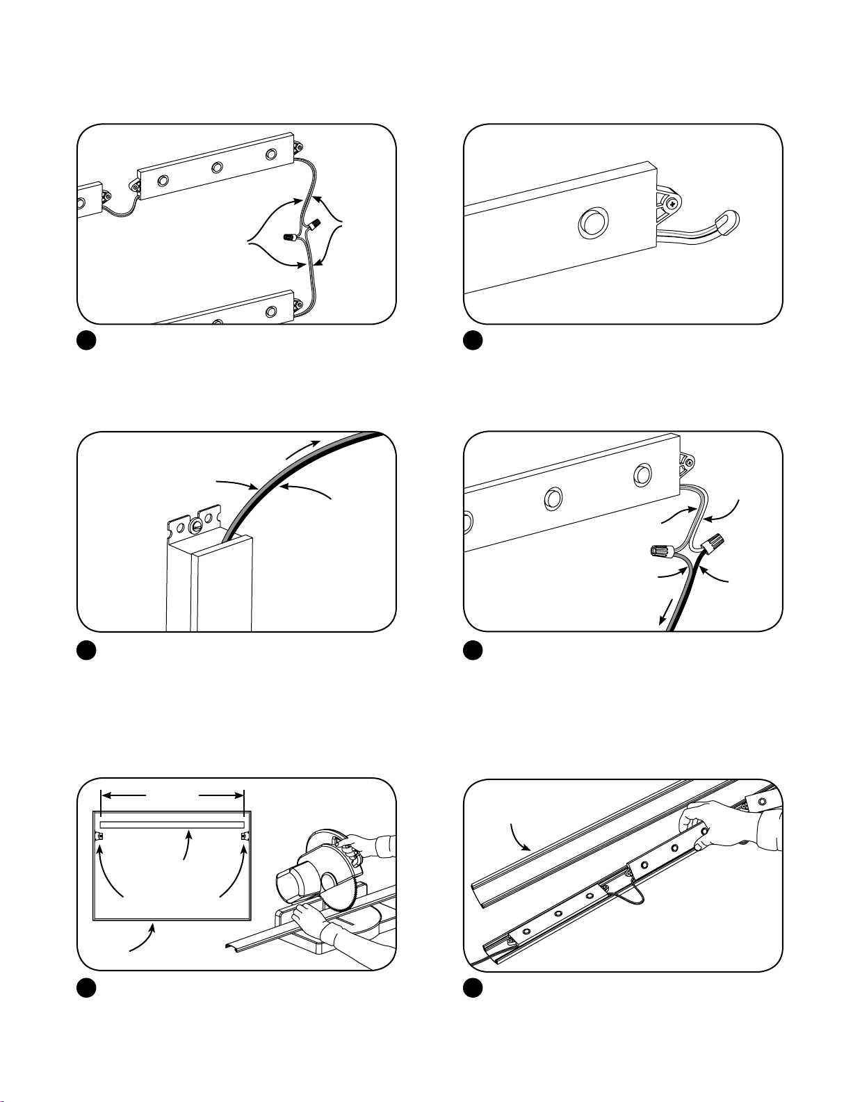
Snap together tube halves. Feed wire through assembly end cap and slide into
assembly end cap.
3 4
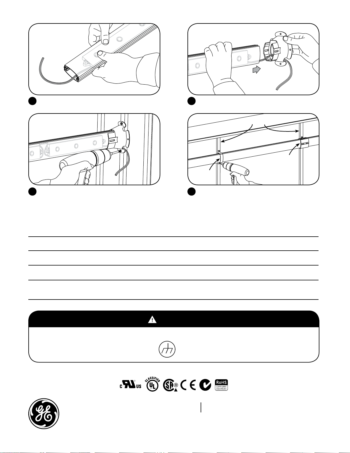
Place Tetra PowerStrip Assembly into correct position
and fasten assembly end cap to the sign with two
#6 (M3) screws.
When mounting horizontally assembly supports MUST
BE used to support tubes approximately every 4 ft.
(1.22 m) by mounting assembly supports around tubes
and securing into support stringers with screws.
OPTIONAL: Install a tube connector for longer spans
up to 10 ft. (3.05 m) and push tube ends into connector.
5 6
BEFORE YOU BEGIN
Read these instructions completely and carefully.
WARNING/ADVERTISEMENT
Risk of electrical shock. Disconnect power before
servicing or installing product.
Risque de choc électrique. Couper l’alimentation
avant le dépannage ou avant l’installation du produit.
10
10
12 3 4
5
6
7 8 9
Support stringers
Tube
connector
Assembly
support


 User manual")