GE Bently Nevada 330400 User manual

-~
ARTISAN
®
~I
TECHNOLOGY
GROUP
Your definitive source
for
quality
pre-owned
equipment.
Artisan Technology
Group
Full-service,
independent
repair
center
with
experienced
engineers
and
technicians
on staff.
We
buy
your
excess,
underutilized,
and
idle
equipment
along
with
credit
for
buybacks
and
trade-ins
.
Custom
engineering
so
your
equipment
works
exactly as
you
specify.
•
Critical
and
expedited
services
•
Leasing
/
Rentals/
Demos
• In
stock/
Ready-to-ship
•
!TAR-certified
secure
asset
solutions
Expert
team
ITrust
guarantee
I
100%
satisfaction
All
tr
ademarks,
br
a
nd
names, a
nd
br
a
nd
s a
pp
earing here
in
are
th
e property of
th
e
ir
r
es
pecti
ve
ow
ner
s.
Find the GE / Bently Nevada 330400-02-00 at our website: Click HERE

Operation Manual
Bently NevadaTM Asset Condition Monitoring
BENTLY
NEVADA
MADE IN U.S.A.
PN 3304XX
xxx mv/c
(xxx mV/m/s2)
CE
330400 and 330425 Accelerometer
imagination at Part Number 127088-01
Rev. H(08/07)

Contact information
The following ways of contacting Bently Nevada are provided for those times when you
cannot contact your local representative:
Mailing Address 1631 Bently Parkway South
Minden, Nevada USA 89423
USA
Tel ep ho ne 1.775.782.3611
1.800.227.5514
Fax 1.775.215.2873
Internet www.ge-energy.com/bently

330400 and 330425 Accelerometer Operation Manual
Additional Information
Notice:
This manual does not contain all the information required to operate and me
the product. Refer to the following manuals for other required information.
lintain
3300/25 Dual Accelerometer Input Monitor (Peak) Maintenance Manual
(Part Number 80181-01)
3300/26 Dual Accelerometer Input Monitor (RMS) Maintenance Manual
(Part Number 86800-01)
2201 Operation and Maintenance Manual (Part Number 100875-01)
3500/42 Proximitor/Seismic Monitor Module Operation and Maintenance
Manual (Part Number 129773-01)
Product Disposal Statement
Customers and third parties, who are not member states of the European Union, who are
in control of the product at the end of its life or at the end of its use, are solely
responsible for the proper disposal of the product. No person, firm, corporation,
association or agency that is in control of product shall dispose of it in a manner that is
in violation of any applicable federal, state, local or international law. Bently Nevada LLC
is not responsible for the disposal of the product at the end of its life or at the end of its
use.

Contents
1. Operating Information1
1.1 Application1
1.2 Principle of Operation1
1.3 Compatible Monitoring Systems2
2. Installation 4
2.1 Receiving Inspection4
2.2 Installing the Accelerometer4
2.2.1 Positioning4
2.2.2 Mounting 4
2.2.3 Routing Cable5
2.2.4 Routing Conduit5
2.2.5 Routing Armored Cable5
2.2.6 Sealing the Interconnect Cable6
2.3 Power and Signal Connections6
2.3.1 3300 MONITORING SYSTEM6
2.3.2 2201 MONITORING SYSTEM6
2.3.3 3500 MONITORING SYSTEM7
2.3.4 EXTERNAL POWER SUPPLY7
3. Maintenance12
3.1 Performance Test Procedure12
3.2 Polarity Test Procedure12
4. Field Testing and Troubleshooting14
4.1 Fault Indication #1 Cause/Solution14
4.2 Fault Indication #2 Cause/Solution15
5. Specifications16
5.1 330400 Accelerometer16
5.1.1 Electrical 16
5.2 330425 Accelerometer17
5.2.1 Electrical 17
5.2.2 Environmental for the 330400 and the 330425 Accelerometer18
5.2.3 Mechanical for the 330400 and 330425 Accelerometer18
5.2.4 Interconnect Cable for the 330400 and 330425 Accelerometer18
5.2.5 Standard Armored Interconnect Cable:19
5.3 Mechanical Outline21
5.4 330400 Accelerometer Frequency Response22
5.5 330425 Accelerometer Frequency Response23

330400 and 330425 Accelerometer Operation Manual
6. Accessories and Spare Parts 24
6.1 330400 Accelerometer Options 24
6.1.1 330400 Accelerometer 24
6.1.2 Mounting Stud: Option A 24
6.1.3 Agency Approvals: Option B 24
6.2 330425 Accelerometer Options 24
6.2.1 330425 Accelerometer 24
6.2.2 Mounting Stud C Option A 24
6.2.3 Agency Approvals C Option B 25
6.3 Transducer Housing 25
6.4 Interconnect Cable Options 25

Section 1- Operating Information
1. Operating Information
This section contains information that will help you prepare for the installation of
the Accelerometer Systems. General information for typical applications,
principles of operation, and monitoring compatibility of the Accelerometers are
presented in this section.
1.1 Application
Accelerometers are very effective when used for the measurement of high
frequency vibrations. Supplemental high frequency casing measurements are
typically required for measuring gear mesh and blade pass frequencies. Section
2explains the proper installation of the Accelerometers.
Application Advisory: If casing acceleration measurements are being
made for the overall protection of a machine, thought should be given to
the usefulness of the measurement for each application. Most common
machine malfunctions, such as unbalance, misalignment, etc., occur on
the rotor and originate as an increase or a change in rotor vibration. For
any casing measurement alone to be effective for overall machine
protection, a significant amount of rotor vibration must be faithfully
transmitted to the machine casing or mounting location of the
transducer. In addition, care should be exercised in the physical
installation of the acceleration transducer on the bearing housing or
machine casing. Improper installation may result in a decrease of the
transducer amplitude and frequency response and the generation of
false signals that do not represent vibration on that particular machine.
1.2 Principle of Operation
The Accelerometer is made up of a piezoelectric shear-mode element and
electronics. When subjected to machinery vibration, this mass/spring system
exerts a force on the piezoelectric ceramic, which generates a charge proportional
to that force. The electronics converts the charge to a voltage that can be sent to
a Bently Nevada monitoring system.
The 330400 and 330425 Accelerometers are designed to monitor vibration
frequencies ranging from 10 Hz to 15 kHz. The calibrated scale factor and
maximum acceleration for the Accelerometers are shown in Table 1.
Table 1-1.
Transducer Scale Factor Maximum
Model (mV/g ± 5%) Acceleration
330400
330425
100 50
25 75
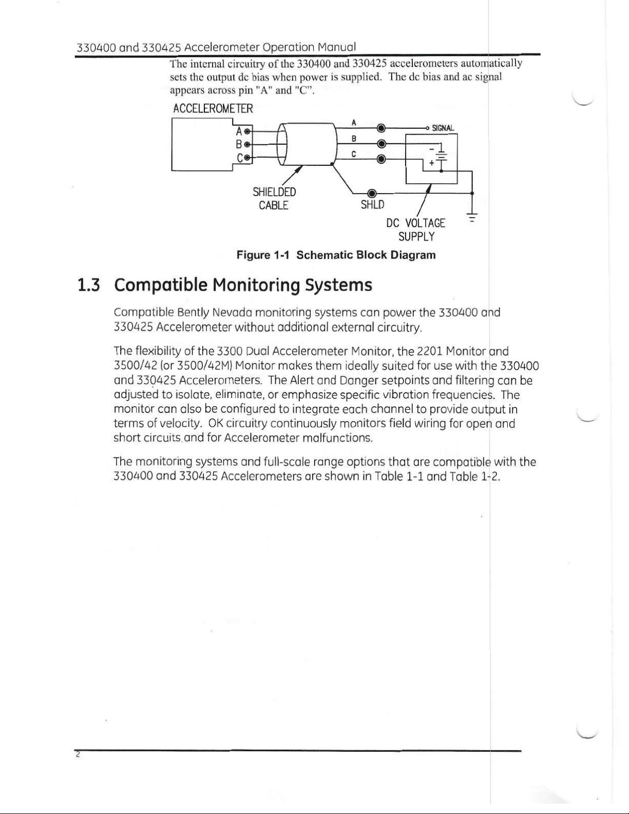
The 330400 and 330425 Accelerometers are three wire transducers which
require external power supplies. The power supply voltage is -24 Vdc. A
simplified schematic block diagram of the 330400 and 330425 Accelerometer
appears in Figure 1-1.
1

330400 and 330425 Accelerometer Operation Manual
A® SIGNAL
Bo 0-1
Co \1 0
The internal circuitry of the 330400 and 330425 accelerometers automatically
sets the output dc bias when power is supplied. The dc bias and ac signal
appears across pin "A" and "C".
ACCELEROMETER
SHLD
0
DC VOLTAGE
SUPPLY
Figure 1-1 Schematic Block Diagram
SHIELDED
CABLE
1.3 Compatible Monitoring Systems
Compatible Bently Nevada monitoring systems can power the 330400 and
330425 Accelerometer without additional external circuitry.
The flexibility of the 3300 Dual Accelerometer Monitor, the 2201 Monitor and
3500/42 (or 3500/42M) Monitor makes them ideally suited for use with the 330400
and 330425 Accelerometers. The Alert and Danger setpoints and filtering can be
adjusted to isolate, eliminate, or emphasize specific vibration frequencies. The
monitor can also be configured to integrate each channel to provide output in
terms of velocity. OK circuitry continuously monitors field wiring for open and
short circuits and for Accelerometer malfunctions.
The monitoring systems and full-scale range options that are compatible with the
330400 and 330425 Accelerometers are shown in Table 1-1 and Table 1-2.
2

Section 1- Operating Information
Table 1-2. Compatible Full-Scale Range Options for the 330400 Accel
Monitoring System Compatible Full-scale with No Integration Full-Scale with Integration
pk rms pk rms
3300/25 Compatible with all full-scale range options Compatible with all full-scale
range options
3300/26 0to 5 g
0to 2 g
0to 10 g
0to 20 m/s2
0to 50 m/s2
0to 100 m/s2
2201 Oto 2 g 0 to 2 g
0to 5 g 0 to 5 g
OtolOg OtolOg
0to 20 m/s2 0 to 20 m/s2
0to 50 m/s2 0 to 50 m/s2
0to 100 mis2 0 to 100 m/s2
3500/42
or
3500/42M
See manual part number 129773-01 for more
details
0to 1 in/s
0to 2 in/s
0to 25 mm/s
0to 50 mm/s
0to 1 in/s
0to 2 in/s
0to 25 mm/s
0to 50 mm/s
0to 1 in/s
0to 2 in/s
0to 25 mm/s
0to 50 mm/s
Table 1-3. Compatible Full-scale Range Options for the 330425 Accel
Monitoring System Compatible Full-Scale with No Integration Full-Scale with Integration
pk rms pk rms
3300/26
2201
3500/42
Or
3500/42M
0to 20 g
0to 25 g
0to 40 g
0to 50 g
0to 200 m/s2
0to 250 m/s2
0to 400 m/s2
0to 500 m/s2
0to 20 g 0 to 20 g
0to 25 g Oto 25 g
Oto 40g Oto 40g
0to 50 g 0 to 50 g
0to 200 m/s2 0 to 200 m/s2
0to 250 m/s2 0 to 250 m/s2
0to 400 m/s2 0 to 400 m/s2
0to 500 m/s2 0 to 500 rn/s2
See manual part number 129773-01 for more
details
0to 100 mm/s
0to 100 mm/s 0 to 100 mm/s
3

330400 and 330425 Accelerometer Operation Manual
2. Installation
2.1 Receiving Inspection
Inspect the components of the order when they are received to see if there was
any damage during shipping. Keep all shipping forms and invoices. If any
shipping damage is apparent, file a claim with the carrier and submit a copy to
Bently Nevada. Include all model numbers and serial numbers with the claim.
We will either repair or replace damaged parts according to the terms and
conditions of the sale.
The Accelerometers are shipped in a protected box and the connector is
protected with a plastic cap. The Accelerometers are sensitive instruments and
these precautions help to prevent damage during shipping.
2.2 Installing the Accelerometer
2.2.1 Positioning
For optimum performance and accurate measurements, place the accelerometer
at a position on the machine casing that is most responsive to vibration. Proper
placement often depends on the application. Bently Nevada offers Machinery
Diagnostic Services that can help you find the optimum location for your
application.
2.2.2 Mounting
Follow these steps to install the Accelerometer:
Step 1: Check that the ambient and surface temperatures of the installation
location are within the temperature rating of the Accelerometer: -55° to 121°C ( -
67° to 250°F).
Step 2: Check that the mounting site is flat, clean and dry. The accelerometer
requires a flat area that is 28.6 mm dia. (1.125 in. dia.) for mounting. For best
results the mounting surface should have a roughness of no more than 0.813 pm
(32 pin) rms and a flatness of at least 25.4 pm (0.001 in) TIR.
Step 3: Drill and tap a hole in the mounting center of the prepared surface as
required by the integral mounting stud. The 330400 and 330425 Accelerometers
have two mounting stud options: 1/4-28 UNF-2B X 0.35 in and M8X1-6g X 8.89
mm thread. The hole should be perpendicular to the mounting surface within ± 6
minutes.
Step 4: This step only required for accelerometers with a serial number not
preceded by the letter "G". Lightly grease the lower face of the mounting adapter
4

Section 2 - Installation
with Dow Corning 340 or equivalent grease and then screw the adapter into the
mounting surface. The grease is required to ensure good coupling between the
adapter and the mounting surface at high frequencies. A light oil may also be
used.
Step 5: This step only required for accelerometers with a serial number not
preceded by the letter "G". Use a torque wrench with a 1" hex socket. Tighten the
adapter to the mounting surface with a torque of 6.8 ± 1.4 N•m (60 ± 12 inAlb). To
remove the adapter, apply a counterclockwise torque to its hex base.
Step 6: Lightly grease the accelerometer mating surface with Dow Corning 340
or equivalent grease and then screw the accelerometer into the mounting
surface. The grease is required to ensure good coupling between the
accelerometer and the mounting surface at high frequencies. A light oil may also
be used.
Step 7: Use a torque wrench with a 15/16" hex socket. Tighten the accelerometer
to the mounting surface with a torque of 3.3 ± 0.56 N.m (30 ± 5 in-lb). To remove
the accelerometer, apply a counterclockwise torque to its hex base.
2.2.3 Routing Cable
When installing the interconnect cable, route it away from the moving
components of the machine and avoid small bending radii. To minimize noise,
avoid routing cables near or in the same conduit, raceway, or cable tray with
power lines. Prevent the cable from bending sharply, twisting, knotting, or
straining. Route the cable through the conduit to prevent physical damage. If the
cable must be routed inside lubrication oil lines, be sure it will not be subjected to
temperatures exceeding its specified operating range.
2.2.4 Routing Conduit
To route cable through the conduit, connect one end of the conduit to the
protective enclosure or other structure in which the monitor is mounted. Connect
the other end of the conduit rigidly to a structure near the accelerometer. Before
pulling cable through the conduit, protect the terminal lugs by wrapping the cable
with tape or a similar covering. Be sure that the cable does not rub against rough
or sharp surfaces.
2.2.5 Routing Armored Cable
Use armored cable if the cable is not routed inside conduit. Secure the cable to
the supporting surfaces with clips or similar devices. Connect one end of the
armor directly to the enclosure or other structure in which the monitor is
mounted. Connect the other end of the armor rigidly to a structure near the
330400 and the 330425 Accelerometer. The recommended minimum bend
radius for armored cable is 38.1 mm (1.5 in).

330400 and 330425 Accelerometer Operation Manual
2.2.6 Sealing the Interconnect Cable
^CAUTION
When the conduit is routed through
hazardous areas, the ends of the conduit
must be sealed to prevent hazardous
gases from escaping into non-hazardous
areas. Consult local authorities for
approved sealing methods in hazardous
areas.
If the differential pressure between the ends of the connector cable is less than
one atmosphere, use one of the following cable sealing techniques:
1. ZY5 cable seal similar to Bently Nevada part number 10076-AA.
2. Bently Nevada low-pressure cable seal, part number 43501.
2.3 Power and Signal Connections
Bently Nevada supplies interconnect cables with terminal lugs and a 3-socket
mating connector for the 330400 and the 330425 Accelerometer. Interconnect
cables are sold separately (see 1for the cable options).
At the accelerometer end, tighten the 3-socket mating connector to the
accelerometer's MIL-C-5015 connector. At the monitor end of the cable, use the
wiring instructions for the appropriate monitoring system below.
Note: the wiring instructions assume that the interconnect cable is the
standard Bently Nevada cable part number 16925 - XX.
2.3.1 3300 MONITORING SYSTEM
Connect the cable "A" lead to the "IN" terminal on the monitor, the "B" lead to the
"PWR" terminal, and the "C" lead to the "COM" terminal. The terminal connections
for the 3300 Dual Acceleration Monitor appear in Figure 2-1. Refer to the 3300/25
Peak and 3300/26 RMS Dual Acceleration Input Monitor Maintenance Manual
(part number 80181-01 and 86801-01) for further information.
2.3.2 2201 MONITORING SYSTEM
Connect the cable "A" lead to "SIG/A" terminal on the monitor, the "B" lead to
"PWR/B", and the "C" lead to "COM". The terminal connections for the 2201
Monitoring System appear in Figure 2-2. Refer to the 2201 Monitoring System
Operation and Maintenance Manual (part number 100875-01) for further
information.
6

Section 2 - Installation
2.3.3 3500 MONITORING SYSTEM
Connect the cable "A" lead to "SIG/A" terminal on the monitor, the "B" lead to
"PWR/B", and the "C" lead to "COM". The terminal connections for the 3500/42
Monitoring System appear in Figure 2-3 and Figure 2-4. Refer to the 3500/42
Operation and Maintenance Manual (part number 129773-01) and 3500 Field
Wiring Diagram Package (part number 130432-01) for further information.
Application Alert: Miswiring the accelerometer to an external power
supply without limiting the current to be less than 15 mA will
permanently damage the accelerometer.
2.3.4 EXTERNAL POWER SUPPLY
Using the 16925 interconnect cable, connect the "B" lead to the " - " terminal of
the power supply and the "C" lead to the " + " terminal of the power supply. The
"A" lead of the cable is the output of the Accelerometer. Turn on the power
supply. Adjust the voltage to -24 ± 0.5 Vdc. Set the current limit of the power
supply to be less than 15 mA. Measure the dc voltage across the "A" and "C" lead.
The voltage should be between -8 and -9 Vdc. If it is not, turn off the power
supply immediately and check for proper connections. The terminal connections
of the external power supply appear in figure 2-4.
SHIELD
x..R v0 z RENS TER
Ltt
ALA. RELAY OUTPUTS
SIGNAL INPUT
RELAY MODULE
DUAL RELAYS
RED
BLACK
WHITE
SHIELD (GREEN)
(TO SINGLE EARTH POINT GRID)
CHANNEL B
00HC
ft
MACHINE
CHANNEL A
MACHINE
ACCELEROMETER PIN OUT
Figure 2-1 Accelerometer/3300 System Connections Using 16925
Interconnect Cable
7

330400 and 330425 Accelerometer Operation Manual
MONITOR O OK
moN EOM
ACCELEROMETER PIN OUT
(-OUR
CHAN1‘.._
A.10, TOR
om/B
c SC/A
MR/13
Cam
SiC/A
mCie
SC/A
PRO/S
COM
S1S/A
Cam
®®S(S)N®SSNOCS)®®
PWR/B
COM
SIG/A
PWR/B
COM
SIG/A
PWR/B
COM
SIG/A
PWR/B
COM
SIG/A
COM
RED
BLACK
WHITE
SHIELD (GREEN)
TO SINGLE EARTH POINT
Figure 2-2 Accelerometer/2201 System Connections Using 16925
Interconnect Cable
8

Section 2 - Installation
PROX/SEISkre
I/O MODULE
PVIA
CCM
SNLO
PNR/6
COM
93/8
SHED
RED
—HLACK
WHITE
m
cam_
Aml
gg
Fe- 1
PV,/13 C
OM 0 ,,
9C/A 0 ,
SKI) 0
PVIRTM
CO Co1 Eli
2./8 0 4
SHt0 D
EB
SR
1338 M IH
RE,
CO
REC1 IWi
COM
REC2
COM C
REC3
COM
REC4
Ell
O
3500/42 PROX/SEISMIC I/O MODULE
WITH VTERNAL TERMINATIONS
WITHOUT BARRIERS
ACCELEROMETER PIN OUT
Figure 2-3 Accelerometer/3500 System Connections Using 16925
Interconnect Cable
9

330400 and 330425 Accelerometer Operation Manual
3500/42 PROX/SEISMIC I/O MODULE
WITH EXTERNAL TERMINATIONS
WITHOUT BARRIERS
ACCELEROMETER PIN OUT
CD ®CDCD CDCD
C[DCD
lova
R
BLACK
EXTERNALTERMINATION BLOCK ED
'28015-02SHOWN L
GREEN
WHITE
MACHINE
Figure 2-4 Accelerometer/3500 System Connections Using 16925
Interconnect Cable and External Termination Block.
10

Section 2 - Installation
ACCELEROMETER PIN OUT
OSC:LLOSCOPE
0
I/
BLACK
0I REP
POWER SUPPLY
24 Vdc
WHITE
SHIELD (GREEN)
Figure 2-5 Accelerometer/External Power Supply Connections Using 16925
Interconnect Cable
11

330400 and 330425 Accelerometer Operation Manual
3. Maintenance
This section shows how to check the performance of the 330400 and 330425
Accelerometers. Table 3-1 lists the recommended maintenance equipment. If the
equipment is not available, contact the nearest Bently Nevada field office, or
return the transducer to the factory or a testing laboratory for testing.
Table 3-1. Recommended Maintenance Equipment
Recommended Equipment Specification
AShake Table
Bently Nevada Monitoring Systems:
3300, 2201, or 3500
AVoltmeter
3.1 Performance Test Procedure
Step 1: Mount the accelerometer on a shake table.
Step 2: Connect the cable to the accelerometer and the monitor as shown in
section 2.
Step 3: Shake the accelerometer at 100 Hz with a known acceleration level.
Step 4: Verify the accelerometer output on the monitor or a Voltmeter.
Note: The accuracy of the system can be improved by calibrating the
monitor and the shake table separately before performing the system
loop check.
3.2 Polarity Test Procedure
Use this test to verify the proper phase response. An improper phase will
adversely affect the use of the accelerometer for machinery diagnostics.
Step 1: Power up the accelerometer as shown in Figure 2-5.
Step 2: Set the time base on the oscilloscope to 20 milliseconds/division.
Step 3: Hold the transducer in hand and tap the bottom. Observe that the
waveform on the oscilloscope first goes positive as shown in Figure 3-1. If the
wave form goes negative first, contact the nearest Bently Nevada office for
assistance.
12

Section 3 - Maintenance
Display Goes
Positive First
.-- Time
Figure 3-1 Polarity Check Oscilloscope Display
13

330400 and 330425 Accelerometer Operation Manual
4. Field Testing and Troubleshooting
Use the following procedures to test an installed 330400 and 330425
Accelerometer and isolate a suspected malfunction. The 330400 and 330425
Accelerometers are hermetically-sealed units with no adjustments or field
repairable components. If you determine that the accelerometer is not
functioning properly, contact the nearest Bently Nevada office for assistance.
When the 330400 and 330425 Accelerometers are used with a Bently Nevada
monitoring system, a fault may be due to an accelerometer malfunction, a
malfunction in the field wiring, a malfunction in the monitor itself, or a level of
vibration that exceeds the OK limit. Before placing a call to our service group, use
the steps below to troubleshoot the suspected problems.
4.1 Fault Indication #1 Cause/Solution
4.1.1.1 Bently Nevada Monitor OK LED is off
The vibration level has exceeded the OK limit
Connect a voltmeter to the "IN" and "COM" on the SIRM terminals on the back of
the monitor rack. Measure the dc voltage. The voltage should be between -8.0
and -9.0 Vdc.
Monitor Power is off.
Check that the monitor power supply is plugged in and that the power is on.
Interconnect cable is disconnected, connected loosely, connected to the
wrong monitor or mis-wired.
Verify that the accelerometer is connected to the correct monitor and to the
correct monitor terminals. Check that the screws on the Signal Input Relay
Module are tight.
Interconnect cable is not connected or connection is loose at the
accelerometer.
Verify that the accelerometer is connected to the cable.
14
This manual suits for next models
1
Table of contents
Other GE Measuring Instrument manuals

GE
GE N60 User manual

GE
GE Moisture monitor series 3 Owner's manual

GE
GE Moisture Image 1 Series User guide

GE
GE RHM 04 User manual

GE
GE Phasor CV User manual

GE
GE TransPort PT878GC User manual

GE
GE Druck DPI 705 User manual

GE
GE JXSOUSV1 User manual

GE
GE Moisture Target Series 6 User manual

GE
GE PanaFlow MV80 User manual
Popular Measuring Instrument manuals by other brands

NUCLEONIX SYSTEMS PRIVATE LIMITED
NUCLEONIX SYSTEMS PRIVATE LIMITED RM704 instruction manual

Bacharach
Bacharach MGS-250 installation guide

GARANT
GARANT XCONTROL user guide

TSI Incorporated
TSI Incorporated 4140 Operation and service manual

Triplett
Triplett CableRater instruction manual

Reely
Reely 1082712 operating instructions