CGS990 DOUBLE OVEN -2K5
31-14982-2 07-11
GAS, FREESTANDING, SELF-CLEANING RANGE
DOOR LATCH
The latch mechanism is thermally operated. When the SELF
CLEAN cycle is selected, the latch will automatically lock for
cleaning and unlock after cleaning. The door locks immediately
and will remain locked until the oven has dropped below these
temperatures (about 420˚F.)
UPPER LOCK MECHANISM AND LOCK SWITCH
ACCESS
1. Remove oven door.
2. Remove the cooktop (see Remove Cooktop in this manual.)
3. Remove manifold panel (remove phillips head screws from burner ame adjustment
switch and 1/4” hex head screws from the underside of the manifold panel.)
4. Remove cover over lock mechanism (remove 1/4” hex head screws on each side of
the cover.)
5. Label and remove wires from lock switch.
6. Remove screws securing lock mechanism to oven frame.
7. Remove mechanism.
Note: After installing mechanism, rotate lock to unlock position to prevent low
temperature lock-up.
LOWER LOCK MECHANISM AND LOCK SWITCH ACCESS
1. If upper door is locked, see Upper Lock Mechanism
and Lock Switch Access to disengage the upper
lock mechanism and remove the upper door.
2. Remove 2 hex screws from front that attach the
lower lock mechanism to the front frame. If lower
door is locked, disengage latch hook to remove
lower oven door.
3. Remove the cooktop (see To Remove Cooktop in
this manual.)
4. Remove manifold panel (remove Phillips
head screw from left and right burner ame
adjustment switch and 1/4” hex head screws
from the underside of the manifold panel.)
5. Remove left side panel (Remove screws at top connecting to burner box. Remove
screws at rear connecting to range back. Remove screw at bottom front connecting to
front frame. Remove screw at top front connecting to side post.)
6.
Lower lock mechanism is located between the upper and lower oven near the front of the unit.
Note: After installing mechanism, rotate lock to unlock position to prevent low
temperature lock-up.
ERC FAILURE CODES
The oven may stop operating but not give an F code on the display immediately. F codes
are stored in nonvolatile eprom memory until the same fault occurs twice consecutively.
After that, the F code will be displayed. F codes can be recalled by pressing together TIMER,
CLOCK, MIN DOWN or 9. While F codes are displayed, pressing MIN UP or 8 and HR, DOWN
or 6 together will clear them.
RELAY CONTACT TO OPERATION TEST
RELAY TERMINALS VOLTAGE IN MODE VOLTAGE IN OFF
BAKE BAKE to N 120 VAC IN BAKE* 0 VAC IN OFF
BROIL BROIL to N 120 VAC IN BROIL** 0 VAC IN OFF
LATCH MDL to N 120 VAC 0 VAC IN OFF
OVEN
LIGHT
LIGHT to L1 120 VAC 0 VAC IN OFF
FAN LO
SPEED
FAN L to N 120 VAC IN CONVECTION
BAKE*
0 VAC IN OFF
FAN HI
SPEED
FAN H to N 120 VAC IN CONVECTION
ROAST*
0 VAC IN OFF
* Be sure to select a temperature or setting
** Must be in Bake cycle. Wait until preheat has completed and call for heat initializes.
FAILURE CODE MEANING & CORRECTIONS
FAILURE CODES WILL BE SHOWN IN THE OVEN CONROL BY PRESSING THE
(TIMER), (8) & (9) KEYS AT THE SAME TIME
FAILURE
CODE MEANING CORRECTION
F0 CLEAR/OFF key input
failure Short for approximately 100 seconds.
F1 Control Failure Loss of element relay redundant driver protection.
F2 Oven temperature
condition due to
sensor input to
control
Oven above 640˚F with Lock input untrue. Oven above
915˚F with Lock input true.
F3 Open Sensor Sensor is 2900 to innite ohms while in a heating
mode.
F4 Shorted Sensor Sensor is 0 to 950 ohms maximum while in a heating
mode.
F6 Failed Gas Valve
Lockout
Open harness switch and/or installed gas lockout
motor.
F7 Shorted key detection
except for slew entry
and Clear/O keys
Short for approximately 40 seconds.
F9 Door lock false
while above
Runaway Setpoint,
Unlatched Door Lock
temperature OR
FAD device setpoint
exceeded.
“Unlock” Latch Changing status to “Lock”. Latch of
Motor changing to “Un-Lock” while above run away set
point.
FC Door Latch error
Unlock home and lock home are try simultaneously.
FD Probe failure
Shorted Probe
FF Control failure
Loss of door motor redundant driver protection.
CIRCUIT TERMINALS OHMS CONDITION
OVEN
SENSOR
6 to 8 1100 OVEN AT ROOM
TEMPERATURE
DOOR
UNLATCHED
3 to 5 0 DOOR LATCH IN BAKE/BROIL
POSITION
DOOR
LATCHED
4 to 5 0 DOOR LATCH IN CLEAN
POSITION
MEAT
PROBE
1 to 2 55000 AT ROOM TEMPERATURE
MEAT PROBE INSERTED
WARNING
Power must be disconnected
before servicing this appliance.
222D6585P010
TO SELF CLEAN IN LOWER OVEN
1. Press SELF CLEAN.
2. Press number pads to enter desired time (4:00 hours is standard).
3. Press START pad.
4. LOr and door will be displayed and LOCKED will be ashing.
CLEAN will be on and
solid indicating the gas valve and doors are locking and the unit is entering self clean.
The gas valve locks rst, then the lower door, then the upper door. The call for heat
will begin once everything has locked successfully. Towards the end of the cycle, the
lower door will unlock, then the upper door, and nally the gas valve. LOCKED will
ash while the doors are unlocking. LOC will ash while the gas valve is unlocking.
TO SELF CLEAN IN UPPER OVEN
1. Turn thermostat to SELF CLEAN position.
2. Press START pad (default time is 5:00 and cannot be changed).
3. UPr and door will be displayed and LOCKED will be ashing.
CLEAN will be on and
solid indicating the gas valve and doors are locking and the unit is entering self clean.
The gas valve locks rst, then the lower door, then the upper door. The call for heat
will begin once everything has locked successfully. Towards the end of the cycle, the
lower door will unlock, then the upper door, and nally the gas valve. LOCKED will
ash while the doors are unlocking. LOC will ash while the gas valve is unlocking.
NOTE FOR SELF CLEAN IN UPPER OR LOWER OVEN: Average clean temperature is
790˚F. Cool down period is 1 hour at the end of the cycle. The self-clean operation
can only be initiated when the range is at room temperature. If any recent oven
cooking has been done, allow the range to cool to room temperature before initiating
a self-clean cycle. If you try to initiate a self-clean cycle in either of the ovens before
the range has reached room temperature, the following will occur: Initially, the
display will look normal. 15 seconds after initiating the cycle, the control will begin
to beep about once every second for approximately 1 minute. After 1 minute, the
beeping will cease and the display will ash the word. LOC. After 15 seconds, the
control will show the time of day, indicating it is now in the standby mode and the
self-clean cycle has been terminated.
OVEN TEMPERATURE CALIBRATION
The bake temperature can be adjusted from its factory calibration (+ or -) 35˚F in 1˚
increments.
1. Press and hold both the BAKE and WARM pads for about 2 seconds until the
display shows SF.
2. Press the BAKE pad. The current oset setting is shown in the display.
3. Enter the desired temperature oset using the number pads.
4. Use the BAKE pad to toggle between +/-.
5. Press START key. The display will return to Time or Day Clock.
BAKE BURNER REMOVAL UPPER OVEN
• Remove oven door and drawer.
• Remove the screws on the oven oor at the back of the oven cavity and remove
oven oor/deector.
• Remove 1/4” hex head screws from the bracket holding the burner to the back
wall of the range.
• Remove the screw at the front of the burner.
• Disconnect the igniter wires.
• Remove the Bake Burner.
BAKE BURNER REMOVAL LOWER OVEN
• Remove oven door and drawer.
• Remove the screws on the oven oor at the back of the oven cavity and remove
oven oor/deector.
• Remove the screw at the front of the burner.
• Disconnect the igniter wires.
• Remove the Bake Burner
BACKGUARD DISASSEMBLY
• Remove screws located on the back of the backguard. (There is a set of screws on
each side.)
• Remove the torx screw on the front inside corner of backguard (1 on each side).
• Gently lift backguard o.
• Be sure to reassemble rear cover and backguard per original assembly.
OVEN BURNER IGNITION SYSTEM
The ignitor is a “Norton” style rectangular glowbar. The ignition circuit consists of
the electronic control, the igniter, and the oven safety valve (gas valve). The three
components are wired in series.
The most important points to know about the ignition system are:
1. THE IGNITOR RESISTANCE DECREASES AS THE IGNITER SURFACE TEMPERATURE
INCREASES.
2. THE SAFETY VALVE OPERATES BY CURRENT, NOT VOLTAGE.
From a cold start, the ignitor needs 30-60 seconds, with voltage applied, to reduce the
electrical resistance enough to provide a minimum of 2.9 amps of current ow in the
series circuit. This is the required current ow needed for the safety valve to open to
supply gas to the burner. The glowbar should provide a steady current ow of between
3.2 to 3.6 amps owing in the circuit. The igniter will remain energized at all times
during burner operation. If the igniter glows red but does not draw at least 2.9 amps,
the fault is usually with the igniter, not the valve. Always check the oven shut-o valve
for a “No Oven” condition.
SENSOR AND LOCK SWITCH CIRCUIT
1
2
3
4
5
6
8
MEAT PROBE CIRCUIT
PINS 1 & 2
UNLOCKED DOOR
LOCKED DOOR
LOCK COMMON
MEAT SENSOR CIRCUIT
PINS 6 & 8
OVEN TEMP SENSOR
1100 OHMS AT ROOM TEMP
2650 OHMS AT CLEAN TEMP
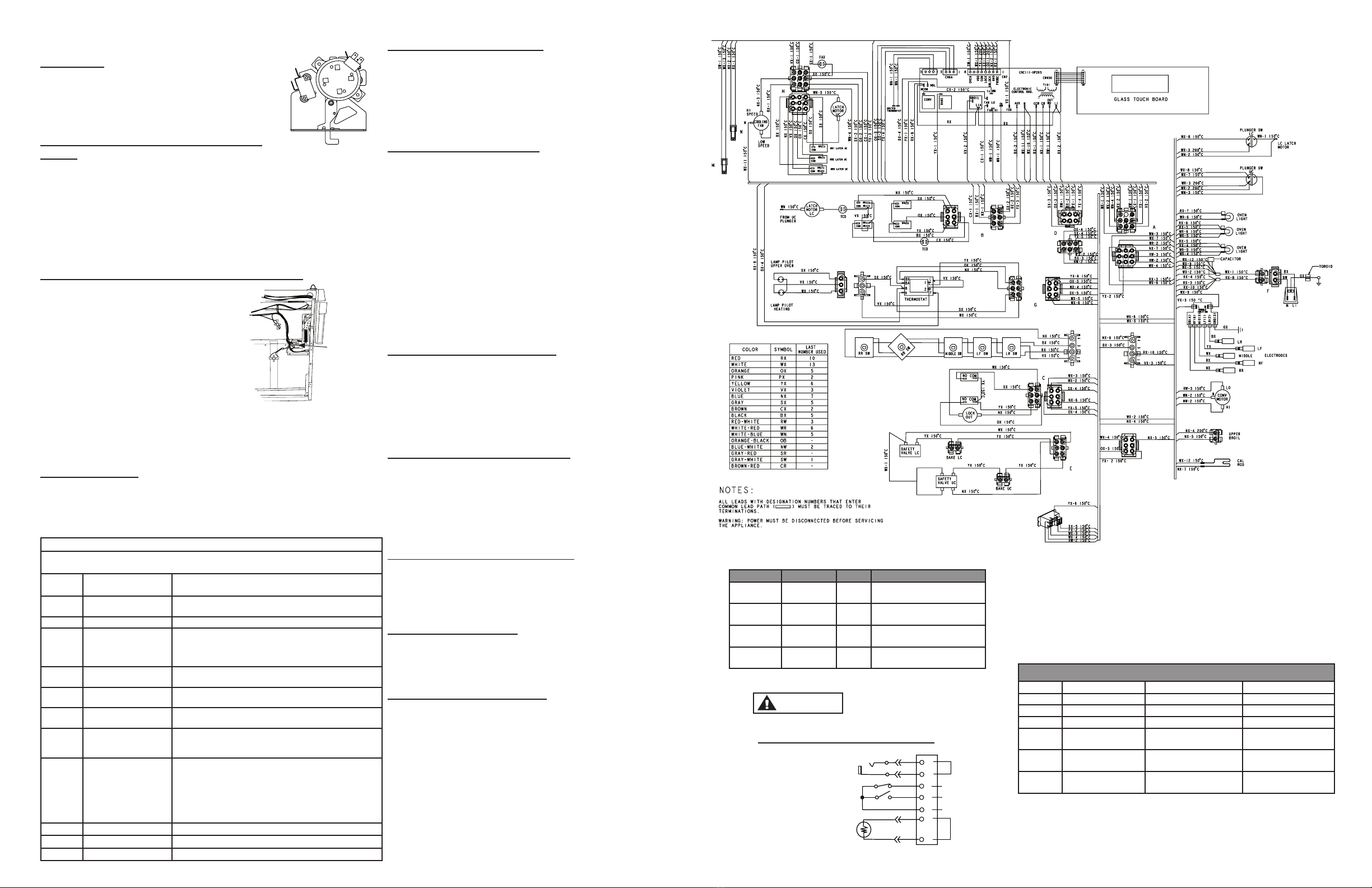
WIRING DIAGRAM
Lower lock
mechanism


