GE JCKS10 User manual

1
If you have questions, call 1.800.561.3344 or visit our website at:
www.geappliances.ca
Built-In Wall Oven
27”(68.6 cm) models
Installation
Instructions JCKS10, JCKP30, JCKP70, PCK916, PCK920
Materials Needed
Strain Relief Clamp
for 1/2”conduit Junction
Box
Wire Nuts
91 cm (36”) of String
Before You Begin
Read these instructions carefully and completely.
•IMPORTANT—Save these
instructions for local inspector’s use.
•IMPORTANT—Observe all
governing codes and ordinances.
• Note to Installer—Be sure to leave these
instructions with the consumer.
• Note to Consumer—Keep these
instructions for future reference.
• Proper installation is the responsibility
of the installer and product failure due
to improper installation is NOT covered
under warranty.
• NOTE—This appliance must be properly
grounded.
•ATTENTION INSTALLER
All electric wall ovens must be hard wired
(direct wired) into an approved junction
box. A plug and receptacle is NOT permitted
on these products.
31-10666-3 11-07 JR
Tools Needed
1/8”(3 mm) Drill Bit and
Electric or Hand Drill Phillips
Screwdriver
Parts Included
(Appearance will vary.)
Screws for Installation
(8-18 x .750 flat head
Phillips wood screws)
30”(76.2 cm) models
JCTP30, JCTP70, PCT916, PCT920
76.2 cm (30″)
Metal Bottom Trim
Assembly
68.6 cm (27″)
Metal Bottom Trim
WB07T10578 – Black
WB07T10579 – SS
Optional 68.6 cm (27″)
Metal Bottom Trim Assembly
(on some models or can be
purchased separately)

2
IMPORTANT SAFETY INSTRUCTIONS
Installation Instructions
For Your Safety
• Be sure your oven is installed properly by
a qualified installer or service technician.
• Be sure the oven is securely installed in a
cabinet that is firmly attached to the house
structure. Weight on the oven door could
cause the oven to tip and result in injury.
Never allow anyone to climb, sit, stand or
hang on the oven door.
• Make sure the cabinets and wall coverings
around the oven can withstand the
temperatures (up to 93°C [200°F])
generated by the oven.
Electrical
Requirements (cont.)
Rating Plate is located on oven side trim,
side front frame or lower front frame.
We recommend you have the electrical wiring
and hookup of your oven connected by a
qualified electrician. After installation, have
the electrician show you where your main
oven disconnect is located.
Check with your local utilities for electrical
codes which apply in your area. Failure to
wire your oven according to governing codes
could result in a hazardous condition. If there
are no local codes, your oven must be wired
and fused to meet the requirements of CAN/
CSA C22.2 No. O-M91 or latest edition.
You must use a three-wire, single-phase A.C.
208Y/120 Volt or 240/120 Volt, 60 hertz
electrical system. If you connect to aluminum
wiring, properly installed connectors approved
for use with aluminum wiring must be used.
WARNING:
The electrical
power to the oven supply line
must be shut off while line
connections are being made. Failure
to do so could result in serious injury
or death.
Rating Plate
Location
Electrical
Requirements
This appliance must be supplied with the proper
voltage and frequency, and connected to an
individual, properly grounded branch circuit,
protected by a circuit breaker or fuse. See the
rating plate located on the oven frame to determine
the rating of the product. Use the chart below to
determine the minimum recommended dedicated
circuit protection.
Recommended
KW Rating KW Rating Circuit Size
240V 208V (Dedicated)
≤4.8 KW ≤4.1 KW 20 Amp
4.9 KW–7.2 KW 4.3 KW–6.2 KW 30 Amp
7.3 KW–9.6 KW 6.3 KW–8.3 KW 40 Amp
9.7 KW–12.0 KW 8.4 KW–10.4 KW 50 Amp

3
EASYINSTALLATIONOFYOURNEW
30"WALLOVEN
Beforeyoubegin-Readtheseinstructionscompletelyandcarefully.
IMPORTANT-Savetheseinstructionsforlocalinspector’suse.
IMPORTANT-OBSERVEALLGOVERNINGCODESANDORDIANCES.
NotetoInstaller-Besuretoleavetheseinstructionswiththeconsumer.
OWNER-Keeptheseinstructionsforfuturereference.
Note-Thisappliancemustbeproperlygrounded(ifapplicable).
Beforeyoubegin-Readthese
instructionscompletelyand
carefully.
IMPORTANT-Savethese
instructionsforlocalinspector’suse.
IMPORTANT-OBSERVEALL
GOVERNINGCODESANDORDIANCES.
NotetoInstaller-Besuretoleave
theseinstructionswiththeconsumer.
OWNER-Keeptheseinstructions
forfuturereference.
Note-Thisappliancemustbe
properlygrounded(ifapplicable).
FORYOURSAFETY
Beforeyoubegin-Readtheseinstructionscompletelyandcarefully.
IMPORTANT-Savetheseinstructionsforlocalinspector’suse.
IMPORTANT-OBSERVEALLGOVERNINGCODESANDORDIANCES.
NotetoInstaller-Besuretoleavetheseinstructionswiththeconsumer.
OWNER-Keeptheseinstructionsforfuturereference.
Note-Thisappliancemustbeproperlygrounded(ifapplicable).
ELECTRICALREQUIREMENTS
Beforeyoubegin-Readthese
instructionscompletelyand
carefully.
IMPORTANT-Savethese
instructionsforlocalinspector’suse.
IMPORTANT-OBSERVEALL
GOVERNINGCODESANDORDIANCES.
NotetoInstaller-Besuretoleave
theseinstructionswiththeconsumer.
OWNER-Keeptheseinstructions
forfuturereference.
Note-Thisappliancemustbe
properlygrounded(ifapplicable).
Beforeyoubegin-Readtheseinstructionscompletelyandcarefully.
IMPORTANT-Savetheseinstructionsforlocalinspector’suse.
IMPORTANT-OBSERVEALLGOVERNINGCODESANDORDIANCES.
NotetoInstaller-Besuretoleavetheseinstructionswiththeconsumer.
OWNER-Keeptheseinstructionsforfuturereference.
Note-Thisappliancemustbeproperlygrounded(ifapplicable).
Beforeyoubegin-Readthese
instructionscompletelyand
carefully.
IMPORTANT-Savethese
instructionsforlocalinspector’suse.
IMPORTANT-OBSERVEALL
GOVERNINGCODESANDORDIANCES.
NotetoInstaller-Besuretoleave
theseinstructionswiththeconsumer.
OWNER-Keeptheseinstructions
forfuturereference.
Note-Thisappliancemustbe
properlygrounded(ifapplicable).
FORYOURSAFETY
Beforeyoubegin-Readtheseinstructionscompletelyandcarefully.
IMPORTANT-Savetheseinstructionsforlocalinspector’suse.
IMPORTANT-OBSERVEALLGOVERNINGCODESANDORDIANCES.
NotetoInstaller-Besuretoleavetheseinstructionswiththeconsumer.
OWNER-Keeptheseinstructionsforfuturereference.
Note-Thisappliancemustbeproperlygrounded(ifapplicable).
Beforeyoubegin-Readtheseinstructionscompletelyandcarefully.
IMPORTANT-Savetheseinstructionsforlocalinspector’suse.
IMPORTANT-OBSERVEALLGOVERNINGCODESANDORDIANCES.
NotetoInstaller-Besuretoleavetheseinstructionswiththeconsumer.
OWNER-Keeptheseinstructionsforfuturereference.
Note-Thisappliancemustbeproperlygrounded(ifapplicable).
ELECTRICALREQUIREMENTS
Beforeyoubegin-Readthese
instructionscompletelyand
carefully.
IMPORTANT-Savethese
instructionsforlocalinspector’suse.
IMPORTANT-OBSERVEALL
GOVERNINGCODESANDORDIANCES.
NotetoInstaller-Besuretoleave
theseinstructionswiththeconsumer.
OWNER-Keeptheseinstructions
forfuturereference.
Note-Thisappliancemustbe
properlygrounded(ifapplicable).
Beforeyoubegin-Readthese
instructionscompletelyand
carefully.
IMPORTANT-Savethese
instructionsforlocalinspector’suse.
IMPORTANT-OBSERVEALL
GOVERNINGCODESANDORDIANCES.
NotetoInstaller-Besuretoleave
theseinstructionswiththeconsumer.
OWNER-Keeptheseinstructions
forfuturereference.
Note-Thisappliancemustbe
properlygrounded(ifapplicable).
Beforeyoubegin-Readthese
instructionscompletelyand
carefully.
IMPORTANT-Savethese
instructionsforlocalinspector’suse.
IMPORTANT-OBSERVEALL
GOVERNINGCODESANDORDIANCES.
NotetoInstaller-Besuretoleave
theseinstructionswiththeconsumer.
OWNER-Keeptheseinstructions
forfuturereference.
Note-Thisappliancemustbe
properlygrounded(ifapplicable).
Beforeyou begin-Read these instructions completely and carefully.
IMPORTANT-Save these instructions for local inspector’s use.
IMPORTANT-OBSERVE ALL GOVERNING CODES AND ORDIANCES.
Noteto Installer- Be sure to leave these instructions with the consumer.
OWNER-Keep these instructions for future reference.
Note-This appliance must be properly grounded (if applicable).
Beforeyou begin-Read these
instructionscompletely and
carefully.
IMPORTANT-Save these
instructionsfor local inspector’s use.
IMPORTANT-OBSERVE ALL
GOVERNINGCODES AND ORDIANCES.
Noteto Installer- Be sure to leave
theseinstructions with the consumer.
OWNER-Keep these instructions
forfuture reference.
Note-This appliance must be
properlygrounded (if applicable).
FORYOUR SAFETY
Beforeyou begin-Read these instructions completely and carefully.
IMPORTANT-Save these instructions for local inspector’s use.
IMPORTANT-OBSERVE ALL GOVERNING CODES AND ORDIANCES.
Noteto Installer- Be sure to leave these instructions with the consumer.
OWNER-Keep these instructions for future reference.
Note-This appliance must be properly grounded (if applicable).
ELECTRICALREQUIREMENTS
Beforeyou begin-Read these
instructionscompletely and
carefully.
IMPORTANT-Save these
instructionsfor local inspector’s use.
IMPORTANT-OBSERVE ALL
GOVERNINGCODES AND ORDIANCES.
Noteto Installer- Be sure to leave
theseinstructions with the consumer.
OWNER-Keep these instructions
forfuture reference.
Note-This appliance must be
properlygrounded (if applicable).
Beforeyou begin-Read these instructions completely and carefully.
IMPORTANT-Save these instructions for local inspector’s use.
IMPORTANT-OBSERVE ALL GOVERNING CODES AND ORDIANCES.
Noteto Installer- Be sure to leave these instructions with the consumer.
OWNER-Keep these instructions for future reference.
Note-This appliance must be properly grounded (if applicable).
Beforeyou begin-Read these
instructionscompletely and
carefully.
IMPORTANT-Save these
instructionsfor local inspector’s use.
IMPORTANT-OBSERVE ALL
GOVERNINGCODES AND ORDIANCES.
Noteto Installer- Be sure to leave
theseinstructions with the consumer.
OWNER-Keep these instructions
forfuture reference.
Note-This appliance must be
properlygrounded (if applicable).
FORYOUR SAFETY
Beforeyou begin-Read these instructions completely and carefully.
IMPORTANT-Save these instructions for local inspector’s use.
IMPORTANT-OBSERVE ALL GOVERNING CODES AND ORDIANCES.
Noteto Installer- Be sure to leave these instructions with the consumer.
OWNER-Keep these instructions for future reference.
Note-This appliance must be properly grounded (if applicable).
Beforeyou begin-Read these instructions completely and carefully.
IMPORTANT-Save these instructions for local inspector’s use.
IMPORTANT-OBSERVE ALL GOVERNING CODES AND ORDIANCES.
Noteto Installer- Be sure to leave these instructions with the consumer.
OWNER-Keep these instructions for future reference.
Note-This appliance must be properly grounded (if applicable).
ELECTRICALREQUIREMENTS
Beforeyou begin-Read these
instructionscompletely and
carefully.
IMPORTANT-Save these
instructionsfor local inspector’s use.
IMPORTANT-OBSERVE ALL
GOVERNINGCODES AND ORDIANCES.
Noteto Installer- Be sure to leave
theseinstructions with the consumer.
OWNER-Keep these instructions
forfuture reference.
Note-This appliance must be
properlygrounded (if applicable).
Beforeyou begin-Read these
instructionscompletely and
carefully.
IMPORTANT-Save these
instructionsfor local inspector’s use.
IMPORTANT-OBSERVE ALL
GOVERNINGCODES AND ORDIANCES.
Noteto Installer- Be sure to leave
theseinstructions with the consumer.
OWNER-Keep these instructions
forfuture reference.
Note-This appliance must be
properlygrounded (if applicable).
Beforeyou begin-Read these
instructionscompletely and
carefully.
IMPORTANT-Save these
instructionsfor local inspector’s use.
IMPORTANT-OBSERVE ALL
GOVERNINGCODES AND ORDIANCES.
Noteto Installer- Be sure to leave
theseinstructions with the consumer.
OWNER-Keep these instructions
forfuture reference.
Note-This appliance must be
properlygrounded (if applicable).
Beforeyou begin-Read these instructions completely and carefully.
IMPORTANT-Save these instructions for local inspector’s use.
IMPORTANT-OBSERVE ALL GOVERNING CODES AND ORDIANCES.
Noteto Installer- Be sure to leave these instructions with the consumer.
OWNER-Keep these instructions for future reference.
Note-This appliance must be properly grounded (if applicable).
EASY INSTALLATION OF YOUR NEW
30" WALL OVEN
Beforeyou begin-Read these
instructionscompletely and
carefully.
IMPORTANT-Save these
instructionsfor local inspector’s use.
IMPORTANT-OBSERVE ALL
GOVERNINGCODES AND ORDIANCES.
Noteto Installer- Be sure to leave
theseinstructions with the consumer.
OWNER-Keep these instructions
forfuture reference.
Note-This appliance must be
properlygrounded (if applicable).
FORYOUR SAFETY
Beforeyou begin-Read these instructions completely and carefully.
IMPORTANT-Save these instructions for local inspector’s use.
IMPORTANT-OBSERVE ALL GOVERNING CODES AND ORDIANCES.
Noteto Installer- Be sure to leave these instructions with the consumer.
OWNER-Keep these instructions for future reference.
Note-This appliance must be properly grounded (if applicable).
ELECTRICALREQUIREMENTS
Beforeyou begin-Read these
instructionscompletely and
carefully.
IMPORTANT-Save these
instructionsfor local inspector’s use.
IMPORTANT-OBSERVE ALL
GOVERNINGCODES AND ORDIANCES.
Noteto Installer- Be sure to leave
theseinstructions with the consumer.
OWNER-Keep these instructions
forfuture reference.
Note-This appliance must be
properlygrounded (if applicable).
Beforeyou begin-Read these
instructionscompletely and
carefully.
IMPORTANT-Save these
instructionsfor local inspector’s use.
IMPORTANT-OBSERVE ALL
GOVERNINGCODES AND ORDIANCES.
Noteto Installer- Be sure to leave
theseinstructions with the consumer.
OWNER-Keep these instructions
forfuture reference.
Note-This appliance must be
properlygrounded (if applicable).
Beforeyou begin-Read these
instructionscompletely and
carefully.
IMPORTANT-Save these
instructionsfor local inspector’s use.
IMPORTANT-OBSERVE ALL
GOVERNINGCODES AND ORDIANCES.
Noteto Installer- Be sure to leave
theseinstructions with the consumer.
OWNER-Keep these instructions
forfuture reference.
Note-This appliance must be
properlygrounded (if applicable).
Place hands on both sides of
the door, and close the oven
door to the removal position,
which is most of the way
closed.
Lift door up and
out until the
hinge arms
clear the slots.
Hinge Clears Slot
Open oven door and remove
literature pack and oven racks.
Remove Installation Instructions
from literature pack and read them
carefully before you begin.
Be sure to place all literature,
Owner’s Manual, Installations, etc.
in a safe place for future reference.
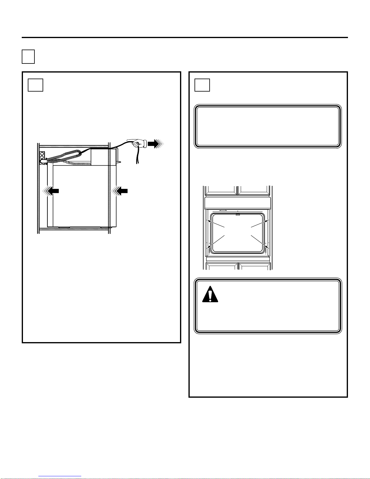
Remove packaging materials. Check
behind hinges and under false bottom.
Remove labels on the outside of the
door, plastic on trims and panel, all
tape around the oven and any shipping
screws securing the oven to the
base pad.
Door removal is not a requirement for
installation of the product, but is an
added convenience. To remove the door:
Open the oven door as far as it will go.
Push both hinge
locks down toward
the door frame,
to the unlocked
position. This may
require a flat blade
screwdriver.
NOTE: The oven door is very heavy.
Be sure you have a firm grip before lifting
the oven door off the hinges. Use caution
once the door is removed. Do not lay the
door on its handle. This could cause dents
or scratches.
Installation Instructions
Pre-Installation Checklist
Hinge
Unlocked
Position
Hinge
Slot
Hinge
Arm
Hinge
Unlocked
Position
Hinge
Slot
Hinge
Arm
DO NOT LIFT THE DOOR
BY THE HANDLE!
Place the oven on a table or platform even
with the cutout opening. (Platform must
support 68 Kg [150 lbs.].)
Remove the bottom trim from the top
of the oven. It will be installed at the end
of the installation process. The trim is
wrapped separately and taped to the
top of the unit
Oven Racks
Literature
Pack

4
Cutout for 27″(68.6 cm) Single Built-In
Ovens only
For JCKP30, JCKP70, JCKS10, PCK916, PCK920 models only.
Cabinet Width 68.6 cm (27”)
Recommended
Cutout Location
from Floor 82.6 cm (32 1/2”)
Cutout Depth 59.7 cm
(23 1/2”) Min.
Cutout Width 63.5 cm
(25”) Min.
64.1 cm
(25 1/4”) Max.
Cutout Height 70.2 cm
(27 5/8”) Min.
71.4 cm
(28 1/8”) Max.
If the cabinet does not have a solid bottom,
two braces or runners must be installed
level with the bottom of the cutout to
support the weight of the oven. For single
ovens, the runners and braces must
support 68 kg (150 lbs.).
Installation Instructions
18"
27"
24"
2" x 4" or
Equivalent
Runners
45.7 cm (18”)
68.6 cm (27”)
61 cm
(24”)
5 cm x 10 cm (2”x 4”) or
equivalent runners level
with bottom of cutout
NOTE: If marks, blemishes or the
cutout opening are visible above the
installed oven, it may be necessary to
add wood shims under the runners and
front trim until the marks or opening
are covered.
These ovens are not approved
for stackable installation.
NOTE: If the cabinet does not
have a front frame and the sides
are less than 1.9 cm (3/4”) thick,
shim both sides equally to
establish the cutout width.
A
Cabinet
Width
68.6 cm
(27”)
12.7 cm
(5”) Max.
from the left
or right
side Junction Box
Location
Recommended
cutout location
from floor 82.6 cm
(32 1/2”)
Allow a minimum
of 50.8 cm (20”) for
clearance to adjacent
corners, drawers, walls,
etc. when door is open
50.8 cm
(20”)
Allow 2.5 cm (1”)
for overlap of oven
over side edges of
cutout
5 cm x 10 cm
(2”x 4”)
or equivalent
runners level
with bottom
of cutout
Cutout Width
63.5 cm
(25”) Min.
64.1 cm
(25 1/4”) Max.
55.9 cm (22”) Min.
above base rail
Cutout
Height
70.2 cm (27 5/8”) Min.
71.4 cm (28 1/8”) Max.
Alternate
Junction Box
Location –
access from
adjacent
cabinet may
be required
Allow 2.5 cm
(1”) minimum
for overlap of
oven top and
bottom of cutout

5
Cutout for 30″(76.2 cm) Single Built-In
Ovens only For JCTP30, JCTP70, PCT916, PCT920 models only.
A
Cabinet Width 76.2 cm (30”)
Recommended
Cutout Location
from Floor 82.6 cm (32 1/2”)
Cutout Depth 59.7 cm
(23 1/2”) Min.
Cutout Width 72.4 cm
(28 1/2”) Min.
72.7 cm
(28 5/8”) Max.
Cutout Height 69.2 cm
(27 1/4”) Min.
69.4 cm
(27 5/16”) Max.
If the cabinet does not have a solid bottom,
two braces or runners must be installed
level with the bottom of the cutout to
support the weight of the oven. For single
ovens, the runners and braces must
support 68 kg (150 lbs.).
Installation Instructions
C
L
SUITABLE
BRACING
TO SUPPORT
RUNNERS
2" x 4" or
EQUIVALENT
RUNNERS
21 5/8"
OVER CENTERLINE
OF CABINET
Suitable
Bracing
to Support
Runners
5 cm x 10 cm
(2”x 4”) or
equivalent
runners level
with bottom
of cutout
54.9 cm
(21 5/8”)
Over Centerline
of Cabinet
NOTE: If marks, blemishes or the
cutout opening are visible above the
installed oven, it may be necessary to
add wood shims under the runners and
front trim until the marks or opening
are covered.
NOTE: If the cabinet does not
have a front frame and the sides
are less than 1.9 cm (3/4”) thick,
shim both sides equally to
establish the cutout width.
Allow a minimum
of 53.3 cm (21”)
for clearance to
adjacent corners,
drawers, walls, etc.
when door is open
24.1 cm
(9 1/2”)
Max.
Recommended
cutout location
from floor
82.6 cm (32 1/2”)
Junction Box
Location
55.9 cm (22”)
to Bottom of
Junction Box
53.3 cm
(21”)
Cutout
Height
69.2 cm
(27 1/4”) Min.
69.4 cm
(27 5/16”) Max.
Cutout Width
72.4 cm
(28 1/2”) Min.
72.7 cm
(28 5/8”) Max.
Opening
between
inside walls
must be at
least 72.4 cm
(28 1/2”) wide
Allow 1.75 cm
(11/16”)
for overlap
of oven over
side edges of
cutout
Cabinet
Width
76.2 cm (30”)
Allow 2.5 cm (1”)
for overlap of
oven top and
3.2 cm (11⁄4
”)
bottom of cutout
These ovens are not approved
for stackable installation.

6
Installation Instructions
Cutout for 27″(68.6 cm) Single Built-In Ovens only
Under Counter For JCKP30, JCKP70, JCKS10, PCK916, PCK920 models only.
NOTE: This oven is only approved to
be installed under the specific models
as labeled on this unit.
63.5 cm (25”)
19.7 cm (7 3/4”)
Max.
61 cm (24”)
91.4 cm (36”)
Typical
Countertop
Height
55.9 cm (22”)
Min. Above
Support
Platform
Top and/or side fillers
may be necessary
if unit is positioned
between existing
cabinets. Be sure
they are attached
securely, since they
will anchor the oven
in the cabinet.
63.5 cm
(25”) Min.
64.1 cm
(25 1/4”) Max.
70.2 cm
(27 5/8”) Min.
71.4 cm
(28 1/8”) Max.
A
Allow 2.5 cm
(1”) overlap
top of oven,
2.5 cm (1”)
overlap side
edges of cutout
and 2.5 cm (1”)
overlap bottom
of cutout
10.2 cm (4”)
Typical
Toekick
Must
match
toekick
height
1.9 cm (3/4”)
Support Platform
Required
MUST SUPPORT 68 Kg (150 LBS.)
240V / 208V
Junction Box
Location (junction
box may be in
adjacent cabinet)
Electric cooktops may be
installed over this oven. See
cooktop installation instructions
for cutout size. See label on top
of oven for approved cooktop
models.
Electrical connections for
cooktop must be located in
an adjacent accessible
location to the right.

7
Installation Instructions
Cutout for 30″(76.2 cm) Single Built-In Ovens only
Under Counter For JCTP30, JCTP70, PCT916, PCT920 models only.
NOTE: This oven is only approved to
be installed under the specific models
as labeled on this unit.
63.5 cm (25”)24.1 cm
(9 1/2”)
Max.
61 cm (24”)
Gas and electrical connections
for gas cooktop must be located
in an adjacent accessible location
to the right.
91.4 cm (36”)
Typical
Countertop
Height
55.9 cm (22”)
Min. Above
Support
Platform
Top and/or side fillers
may be necessary
if unit is positioned
between existing
cabinets. Be sure
they are attached
securely, since they
will anchor the oven
in the cabinet.
Gas or electric cooktops may be installed over this
oven. See cooktop installation instructions for cutout
size. See label on top of oven for approved cooktop
models.
72.4 cm
(28 1/2”) Min.
72.7 cm
(28 5/8”) Max.
69.2 cm
(27 1/4”) Min.
69.4 cm
(27 5/16”) Max.
A
Allow 2.5 cm
(1”) overlap
top of oven,
1.8 cm (11/16”)
overlap side
edges of cutout
and 3.2 cm (1 1/4”)
overlap bottom
of cutout
10.2 cm (4”)
Typical
Toekick
Must
match
toekick
height
1.9 cm (3/4”)
Support Platform
Required
MUST SUPPORT 68 Kg (150 LBS.)
240V / 208V
Junction Box
Location (junction
box may be in
adjacent cabinet)

8
Installation Instructions
Cutout for 30″(76.2 cm) Single Built-In
Ovens only –Over a Warming Drawer
For JCTP30, JCTP70, PCT916, PCT920 models only.
A
NOTE: Additional clearances between cutouts
may be required. Check to be sure the oven
supports above the Warming Drawer location
do not obstruct the required interior depth and
height.
NOTE: Install the
oven only with
specific models
listed on the label
located on top of
the oven.
Anti-Tip Block Against
Rear Wall Per Warming
Drawer Requirement
2”(5.1 cm) Min.
1”(2.5 cm) Min. Above Toekick or
Adjust to Oven Installation Height
Per Warming
Drawer
Requirement
•When installing a Warming Drawer below
a single oven, a separate 120V, 60 Hz,
properly grounded receptacle must
be installed. Refer to installation instructions
packed with the Warming Drawer for specific
installation requirements.

9
Installation Instructions
Electrical Connections
ATTENTION INSTALLER
All electric wall ovens must be hard wired
(direct wired) into an approved junction
box. A plug and receptacle is NOT permitted
on these products.
DO NOT shorten the flexible conduit.
The conduit strain relief clamp must be
securely attached to the junction box
and the flexible conduit must be securely
attached to the clamp. If the flexible
conduit will not fit within the clamp, do not
install the oven until a clamp of the proper
size is obtained.
NOTE TO ELECTRICIAN: The 3 power
leads supplied with this appliance are
CSA recognized for connection to heavier
gauge household wiring. The insulation
of these 3 leads is rated at temperatures
much higher than the temperature rating
of household wiring. The current carrying
capacity of the conductor is governed
by the wire gauge and the temperature
rating of the insulation around the wire.
Turn off the circuit breaker or remove fuses
to the oven branch circuit.
With the oven supported on a table or
platform in front of the cabinet opening,
connect the flexible conduit to the electrical
junction box as shown below. Position the
conduit in such a manner that it will lie on
top of the oven in a natural loop when the
oven is installed. You will need to purchase
an appropriate strain relief clamp to
complete the connection of the conduit
to the junction box.
WARNING: Improper
connection of aluminum house
wiring to copper leads can
result in an electrical hazard or fire.
Use only connectors designed for
joining copper to aluminum and follow
the manufacturer’s recommended
procedure closely.
B2
B1
B
This oven is supplied with a 123 cm (48”)
long flexible conduit consisting of:
3 insulated conductors (copper)
1 bare ground conductor (copper)
Attach conductors to residence wiring as
shown by wiring diagram.
B4
B3
Junction Box
Location
Strain Relief Clamp
(not included)
must be used at
Junction Box
BARE
GROUND
WHITE
Place oven on a
support to assist in
connecting conduit
RED
BLACK
Conduit
GROUND
WIRE
CONDUIT
FROM
OVEN
TO BREAKER PANEL
#12-#10 AWG-COPPER
NMD90 WIRE. FUSE 20
AMP CIRCUIT BREAKERS
BLACK
14 AWG
BLACK
RED
14 AWG
RED
BARE
COPPER
14 AWG
GROUND
WHITE
CSA APPROVED
JUNCTION BOX AND COVER
CSA APPROVED
CONNECTOR
WHITE
(NEUTRAL)
14 AWG

10
WARNING:
Mounting
screws must be used. Failure to
do so could result in the oven
falling out of the cabinet, causing
serious injury.
Installation Instructions
Securing the Oven in the Opening
Drilling the Pilot Holes and
Mounting the Oven
a. Drill through the mounting holes (top and
bottom) of the side trim, for the #8 screws
provided.
b. Secure the oven to cabinet with screws
provided.
NOTE: If the cabinet is particle board, you
must use #8 x 19 mm (3/4”) particle board
screws. These may be purchased at any
hardware store.
Sliding the Oven Into the
Opening
a. Loop (do not tie) a 91 cm (36”) string
around the conduit before the oven is slid
into place. This will keep the conduit from
falling behind the oven.
b. Lift oven into cabinet cutout using the oven
opening as a grip. Carefully push against
oven front frame. Do not push against
outside edges.
c. As you slide the oven back, pull the string
so that the conduit will lie on top of the
oven in a natural loop.
d. When you are sure the conduit is out of the
way, slide the oven 3/4 way back into the
opening. Remove the string by pulling on
one end of the loop.
NOTE: Before drilling the pilot holes,
make sure the oven is pushed as far
back into the opening as it will go
and is centered.
The screws must
be a minimum
of 6 mm (1/4”)
from the front of
the cutout.
Mounting
Hole
Locations
(Hole
Locations
may vary)
C
C1 C2
Pull out on
string loop
while pushing
the oven into
the cabinet

11
a. With oven installed, take the bottom trim
and center it on the bottom front edge of
the cabinet opening.
b. Using the trim
as a template,
mark the center
of each slot
(two total) where
the mounting holes
will be drilled.
c. Remove the trim.
d. Drill pilot holes into
the center of each
template mark.
Installation Instructions
Installing the Metal
Bottom Trim
IMPORTANT: If this unit is ever
removed from the cabinet or the oven
is ever pulled out for service, the trim
must be removed first or damage to
the trim will occur.
C4
Preparing for the Bottom
Trim Installation
C3
Side
Trim
Side
Trim
Metal Lower Trim
* Remove
Lower Trim
Before
Pre-drilling
Mounting
Holes
For 27″(68.6 cm)
models with Lower
Trim in Position,
Mark (2) Mounting
Hole Locations
here
a. Place the bottom metal trim centered over
the pre-drilled mounting holes. Tape the
edges of the trim down to maintain the
alignment.
b. Using two trim screws provided, secure
the bottom trim to the bottom edge of the
cabinet.
For 30″(76.2 cm)
models with
Lower Trim in
Position, Mark
(2) Mounting
Hole Locations
here
Trim Screw Locations for
27″(68.6 cm) models with
Lower Trim
Trim Screw Locations for
30″(76.2 cm) models with
Lower Trim
*

12
Lift the oven door by
placing one hand on
each side. The door is
heavy, so you may need
help. Do not lift the door
by the handle.
With the door at the same angle as
the removal position, which is most of
the way closed, seat the notch of the
hinge arm into the bottom edge of the
hinge slot. The notch of the hinge arm
must be fully seated into the bottom of
the slot.
Open the oven door as far as it
will open.
Push the hinge locks up against the
front frame of the oven cavity, to the
locked position.
Close the oven door.
Installation Instructions
Replacing the Oven Door
D
NOTE:
The oven door is heavy. You
may need help lifting the door high
enough to slide it into the hinge slots.
Do not lift the door by the handle.
D1
D2
D3
D4
D5
Bottom Edge
of Slot
Hinge Arm
Hinge Notch
Notch of Hinge
Securely Fitted
into Bottom of
Hinge Slot
Hinge in
Locked Position

13
Installation Instructions
Remove all protective film, if present,
and any stickers.
Check to be sure that all wiring is
secure and not pinched or in contact
with moving parts.
Pre-Test Checklist
Check that the bottom trim is installed
properly (see page 10).
Check to be sure the mounting screws
are installed and flush with the side trim
(see page 9).
Remove all items from the inside
of the oven.
Check that conduit is securely
connected to the junction box.
Turn on the power to the oven. (Refer
to your Owner’s Manual.) Verify that
the bake and broil units, and all
cooking functions operate properly.
Check that the circuit breaker is not
tripped nor the house fuse blown.
See your Owner’s Manual for
troubleshooting list.
Operation Checklist
NOTE TO ELECTRICIAN: The power
leads supplied with this appliance
are CSA recognized for connections
to larger gauge household wiring.
The insulation of these leads is
rated at temperatures much higher
than the temperature rating of
household wiring. The current
carrying capacity of a conductor
is governed by the wire gauge and
also the temperature rating of the
insulation around the wire.
NOTE: ALUMINUM WIRING
A. WARNING:
IMPROPER
CONNECTION OF ALUMINUM
HOUSE WIRING TO THE COPPER
LEADS CAN RESULT IN AN
ELECTRICAL HAZARD OR FIRE.
B. Splice copper wires to aluminum
wiring using special connectors
designed and CSA approved for
joining copper to aluminum,
and follow the manufacturer’s
recommended connector
procedure closely.
NOTE: Wire used, location and
enclosure of splices, etc., must
conform to good wiring practice
and local codes.

14
Notes

14
Notes

13
Directives d’installation
S’il y a lieu, enlevez la pellicule protectrice
et les étiquettes collées sur le four.
Vérifiez que tout le câblage est bien fixé
et qu’il n’est pas coincé ou en contact
avec des pièces en mouvement.
Liste de vérification avant l’essai
Vérifiez que la garniture inférieure est
bien montée (voir la page 10).
Vérifiez que les vis de montage sont bien
en place et ne dépassent pas la surface
de la garniture latérale (voir la page 9).
Enlevez tous les articles à l’intérieur
du four.
Vérifiez que le conduit est bien connecté
à la boîte de jonction.
Mettez le four en marche (consultez
votre Manuel d’utilisation et d’entretien).
Vérifiez que toutes les opérations de
cuisson fonctionnent adéquatement,
y compris les modes Cuisson (Bake)
et Gril (Broil).
Vérifiez que le disjoncteur n’est pas
déclenché ou le fusible de la maison
grillé.
Consultez le guide de dépannage de
votre Manuel d’utilisation et d’entretien.
Liste de vérification pour l’essai
NOTE À L’USAGE DE L’ÉLECTRICIEN :
Les fils électriques de sortie fournis
avec cet appareil sont approuvés CSA
pour un branchement à du câblage
résidentiel de calibre supérieur. Les
températures nominales de l’isolant
de ces fils sont beaucoup plus élevées
que celles du câblage résidentiel.
La capacité de transport du courant
supportée par un conducteur est
déterminée par le calibre du fil et la
température nominale de l’isolant
autour du fil.
NOTE : CÂBLAGE D’ALUMINIUM
A. AVERTISSEMENT :
LE RACCORDEMENT
INAPPROPRIÉ D’UN CÂBLAGE
RÉSIDENTIEL EN ALUMINIUM À
DES FILS DE SORTIE EN CUIVRE
PEUT ENTRAÎNER UN RISQUE
ÉLECTRIQUE OU D’INCENDIE.
B. Raccordez les fils de cuivre au
câblage d’aluminium à l’aide de
connecteurs spéciaux approuvés
CSA, conçus pour raccorder du
cuivre à l’aluminium, et suivez
minutieusement la procédure
recommandée par le fabricant.
NOTE : Le fil utilisé, l’emplacement
et l’isolation des épissures, etc.,
doivent se conformer aux règles
de l’art et au code de l’électricité
en vigueur localement.

12
Pour soulever la porte
du four, saisissez-la de
chaque côté. La porte est
lourde de sorte que vous
pourriez avoir besoin
d’aide. Ne soulevez pas
la porte par la poignée.
En maintenant la porte à la position
d’enlèvement, qui correspond à peu
près à la position fermée, placez
l’encoche du bras de charnière
dans le bord inférieur de la fente de
la charnière. L’encoche doit être bien
insérée dans le bas de la fente.
Ouvrez la porte du four jusqu’à son
angle maximum.
Placez les verrous de la charnière en
position de verrouillage en poussant
vers le haut contre le panneau frontal
du four.
Fermez la porte du four.
Directives d’installation
Remise en place de la porte du four
D
NOTE :
La porte du four est lourde.
II se peut que vous ayez besoin d’aide
pour la soulever assez haut pour la
glisser dans ses charnières. Ne
soulevez pas la porte par la poignée.
D1
D2
D3
D4
D5
Bord inférieur
de la fente
Bras de
charnière
Encoche du
bras de
charnière
Encoche de la
charnière bien
insérée dans le
bas de la fente
Charnière en
position de
verrouillage

11
a. Une fois le four installé, prenez la garniture
inférieure et centrez-la sur le rebord inférieur
frontal de l’ouverture de l’enceinte.
b. En vous servant
de la garniture
comme gabarit,
marquez le centre
de chaque trou
(deux au total)
à l’endroit où
les trous de montage
seront percés.
c. Enlevez la garniture.
d. Percez des trous de
montage dans le centre
de chaque marque.
Directives d’installation
Installation de la garniture
inférieure métallique
IMPORTANT : La garniture risque d’être
endommagée si elle n’est pas enlevée en
premier lorsque l’appareil est retiré de
l’enceinte pour une réparation ou une
autre raison.
C4
Préparation du montage
de la garniture inférieure
C3
Garniture
latérale
Garniture
latérale
* Enlevez la
garniture
inférieure
avant de
percer les
trous de
montage
Pour les modèles
de 68,6 cm (27 po)
avec la moulure
du bas en place,
marquez
l’emplacement des
trous de montage
(2) tel qu’indiqué.
a. Centrez la garniture inférieure métallique sur
les trous de montage pré-perforés. Fixez les
bords de la garniture avec du ruban adhésif
pour en conserver l’alignement.
b. À l’aide des deux vis de garniture fournies,
fixez la garniture inférieure au bord inférieur
de l’enceinte.
Pour les
modèles de
76,2 cm (30 po)
avec la moulure
du bas en place,
marquez
l’emplacement
des trous de
montage (2) tel
qu’indiqué.
Emplacements des vis de
moulure pour les modèles de
68,6 cm (27 po) avec moulure
du bas
Emplacements des vis de
moulure pour les modèles
de 76,2 cm (30 po) avec
moulure du bas
*
Garniture inférieure métallique

10
AVERTISSEMENT :
Des vis de montage doivent
être utilisées. Le défaut de
se conformer à cette directive peut
occasionner la chute de four et, par
voie de conséquence, des blessures
sévères.
Directives d’installation
Fixation du four dans l’ouverture
Perçage des trous de
guidage et montage du four
a.
Percez à travers les trous de montage
(haut et bas) de la garniture latérale, pour
recevoir les vis #8 fournies.
b. Fixez le four à l’enceinte à l’aide des vis
fournies.
NOTE : Si l’enceinte est en panneaux
de particules, vous devez utiliser des vis
#8 x 19 mm (3/4 po) conçues pour ce
matériau. On peut s’en procurer dans
n’importe quelle quincaillerie.
Mise en place du four dans
l’ouverture
a. Faire passer (ne pas nouer) une ficelle de
91 cm (36 po) autour du conduit avant de
faire glisser le four en place. On évitera
ainsi de faire tomber le conduit en arrière
du four.
b. Agrippez le four par l’intérieur de son orifice
pour le soulever fermement jusque dans
l’ouverture de l’enceinte. Poussez avec
précaution sur le devant du châssis du four.
Ne poussez pas sur les bords extérieurs.
c. Tout en faisant glisser le four vers l’arrière,
tirez sur la ficelle pour que le conduit fasse
une boucle normale sur le dessus du four.
d.
Une fois le conduit dégagé de l’arrière du
four, poussez ce dernier dans l’ouverture
aux trois-quarts de la distance. Tirez sur
une extrémité de la ficelle pour la récupérer.
NOTE : Avant de percer les trous de
guidage, assurez-vous de pousser le
four jusqu’à l’endroit où il doit aller
et de le centrer adéquatement.
Les vis doivent
être à une distance
d’au moins 6 mm
(1/4 po) du devant
de l’ouverture.
Emplacement
des trous de
montage
(L’emplacement
des trous
peut varier)
C
C1 C2
Tirez sur la
ficelle tout
en poussant
le four dans
l’enceinte

9
Directives d’installation
Raccordement électrique
AVIS IMPORTANT À
L’INSTALLATEUR :
Tous les fours muraux encastrés doivent
être raccordés (raccordement direct) dans
une boîte de jonction approuvée. Une fiche
et une prise de courant ne sont PAS
autorisées pour brancher ce produit.
NE PAS raccourcir le conduit flexible.
La bague anti-traction du conduit doit être
fixée fermement à le boîte de jonction et
le conduit flexible doit être fixé fermement
à la bague. Si le conduit flexible n’est pas
ajusté à la bague, procurez-vous une
bague dont la taille est appropriée avant
d’installer le four.
AVIS À L’ÉLECTRICIEN : Les 3 fils
électriques de sortie fournis avec cet
appareil sont approuvés par la CSA pour
un branchement à du câblage résidentiel
de calibre
(Gauge)
supérieur. Les
températures nominales de l’isolant de
ces 3 files sont beaucoup plus élevées que
celles du câblage résidentiel. La capacité
de transport du courant supportée par un
conducteur est déterminée par le calibre
du fil et la température nominale de
l’isolant autour du fil.
Mettez le disjoncteur hors circuit ou enlevez
les fusibles du circuit terminal du four.
Le four reposant sur une table ou une plate-
forme en face de l’ouverture de l’enceinte,
connectez le conduit flexible à la boîte de
jonction, tel qu’illustré ci-dessous. Placez le
conduit de manière à ce qu’il fasse une
boucle normale sur le dessus du four une fois
ce dernier installé. Vous devez vous procurer
une bague anti-traction appropriée pour
terminer la connexion du conduit à la boîte de
jonction.
AVERTISSEMENT :
Le raccordement inadéquat d’un
câblage résidentiel en aluminium
à des fils de sortie en cuivre peut
entraîner un risque électrique ou
d’incendie. Utilisez uniquement des
connecteurs conçus pour raccorder
du cuivre à l’aluminium et respectez
minutieusement la procédure
recommandée par le fabricant.
B2
B1
B
Ce four est doté d’un conduit flexible
de 123 cm (48 po) comportant :
3 conducteurs isolés (en cuivre)
1 conducteur de mise à la terre
dénudé (en cuivre)
Raccordez les conducteurs au câblage
de la maison, tel qu’illustré dans le schéma
de câblage.
B4
B3
CONDUIT
FROM
OVEN
TO BREAKER PANEL
#12-#10 AWG-COPPER
NMD90 WIRE. FUSE 20
AMP CIRCUIT BREAKERS
BLACK
14 AWG
BLACK
RED
14 AWG
RED
BARE
COPPER
14 AWG
GROUND
WHITE
CSA APPROVED
JUNCTION BOX AND COVER
CSA APPROVED
CONNECTOR
WHITE
(NEUTRAL)
14 AWG
FIL DE MISE À LA TERRE
CONDUIT EN
PROVENANCE
DU FOUR
BOÎTE DE JONCTION ET
COUVERCLE APPROUVÉS
PAR LA CSA
VERS LE PANNEAU
DE DISJONCTEURS
FIL DE CUIVRE
NMD90, #12–#10 AWG.
FUSIBLE 20 AMP,
DISJONCTEURS
CONNECTEUR
APPROUVÉ
PAR LA CSA
NOIR
ROUGE
BLANC
(neutre)
BLANC
NOIR
CUIVRE
NU
ROUGE
Emplacement de la
boîte de jonction
Une bague
anti-traction (non incluse)
doit être utilisée à la boîte
de jonction
FIL DE
TERRE NU
BLANC
Placer le four sur
un support pour
faciliter la connexion du conduit
ROUGE
NOIR
Conduit
FIL DE
MISE À LA
TERRE
Other manuals for JCKS10
1
This manual suits for next models
9
Table of contents
Other GE Oven manuals

GE
GE JKP90 User manual

GE
GE PT7800DH2BB User manual

GE
GE Profile PK956DR Manual

GE
GE Profile Advantium PSB2201NSS User instructions

GE
GE CWB7030 User manual

GE
GE JKP15 Series User manual

GE
GE Appliances JVM1950 User manual

GE
GE Profile PT900SRSS Manual

GE
GE GRP16 User manual

GE
GE JRP28SKSS - 24" Double Electric Wall Oven Manual