GE Profile PT920 How to use

GE Appliances
General Electric Company
Louisville, Kentucky 40225
31-9174
30-in. Built-In
Wall Ovens
PT920
PT960
Technical Service Guide
August 2008
GE Consumer & Industrial

– 2 –
IMPORTANT SAFETY NOTICE
The information in this service guide is intended for use by
individuals possessing adequate backgrounds of electrical,
electronic, and mechanical experience. Any attempt to repair a
major appliance may result in personal injury and property
damage. The manufacturer or seller cannot be responsible for the
interpretation of this information, nor can it assume any liability in
connection with its use.
WARNING
To avoid personal injury, disconnect power before servicing
this product. If electrical power is required for diagnosis or test
purposes, disconnect the power immediately after performing the
necessary checks.
RECONNECT ALL GROUNDING DEVICES
If grounding wires, screws, straps, clips, nuts, or washers used to
complete a path to ground are removed for service, they must be
returned to their original position and properly fastened.
GE Consumer & Industrial
Technical Service Guide
Copyright © 2008
All rights reserved. This service guide may not be reproduced in whole or in part
in any form without written permission from the General Electric Company.

– 3 –
Table of Contents
Bake Element......................................................................................................................................................................31
Broil Element.......................................................................................................................................................................22
Component Locator Views...........................................................................................................................................13
Control Board Testing .....................................................................................................................................................40
Control Compartment Access.....................................................................................................................................19
Control Features................................................................................................................................................................ 6
Convection Bake Element.............................................................................................................................................24
Convection Fan Blade and Motor..............................................................................................................................23
Cooling Fan..........................................................................................................................................................................32
Diagnostics and Service Information......................................................................................................................37
Door Assembly...................................................................................................................................................................16
Door Hinge Receivers .....................................................................................................................................................30
Electronic Oven Control.................................................................................................................................................34
ERC Failure Codes.............................................................................................................................................................39
Factory Test Mode............................................................................................................................................................37
Introduction......................................................................................................................................................................... 4
Lock Assembly ...................................................................................................................................................................27
Logic Board..........................................................................................................................................................................25
Lower Oven Control Compartment Access..........................................................................................................20
Meat Probe and Outlet...................................................................................................................................................31
Nomenclature .................................................................................................................................................................... 5
Operational Notes ............................................................................................................................................................12
Oven Component Access Chart ................................................................................................................................15
Oven Components ...........................................................................................................................................................16
Oven Light Assembly ......................................................................................................................................................33
Oven Removal ....................................................................................................................................................................19
Oven Sensor and Door Switch Test..........................................................................................................................38
Oven Temperature Sensor............................................................................................................................................22
Rear Access Panels..........................................................................................................................................................21
Relay and Power Boards...............................................................................................................................................25
Sales Mode...........................................................................................................................................................................12
Schematics and Wiring Diagrams............................................................................................................................42
Side Access Panels...........................................................................................................................................................21
Thermal Switches .............................................................................................................................................................29
Top Access Panels............................................................................................................................................................20
Vent Tube/Smoke Eliminator.......................................................................................................................................23
Warranty ..............................................................................................................................................................................47

– 4 –
Introduction
These 30-in. wall ovens have superior style and performance. These ovens feature electronic controls that
utilize the precision of modern digital technology. Additional features include:
Glass Touch LCD Controls - Combine a smooth, easy-to-clean glass design with large, easy-to-read•
graphics to facilitate easier usage
PreciseAir™ Convection System - Delivers even air and heat circulation for superior baking and roasting•
results
Flat Back Convection Fan - Features a more•
streamlined convection fan that better
accommodates baking and roasting pans
Convection Bake - Provides ideal airflow throughout•
the oven cavity, ensuring better baking results
Convection Roast - Provides even cooking and•
consistent results, roasting meats faster than a
traditional oven
Hidden Bake Oven Interior - Hides previously•
exposed bottom element to deliver a clean interior
appearance
Closed Door Broiling - Provides cleaner broiling with•
a lower wattage heating element
Self Clean Oven - Conveniently cleans the oven cavity without need of scrubbing•
Improved Interior Oven Lighting - Positions lamps diagonally across the top of the oven to promote•
better viewing
Self-Clean, Heavy-Duty Oven Racks - Double coated, porcelain-enameled racks no longer require hand•
cleaning
Extra-Large Oven Capacity - Provides a large oven interior ideal for cooking more items at once•
Single Built-in Oven - May be installed below an Advantium oven or microwave oven and/or above a•
warming drawer
Single Built-In Oven - May be installed below approved gas or electric cooktops•
Double Built-in Oven - May be installed above a warming drawer•

– 5 –
The nomenclature plate is located on the front
left behind the oven door in both the single
and double configurations.
The mini-manual is located in the control
compartment. It is taped to the right side wall.
Feature Pack
Designates features–the higher
the number, the more features.
GE Cooking Product
P = Profile
Configuration
T = 30-in. Wall Oven
Product Color
SS = Stainless Steel
BB = Black
WW = White
Model Year Designator
P T 9 6 0 B M B B
Nomenclature
Nomenclature
The letter designating
the year repeats every
12 years.
Example:
T - 1974
T - 1986
T - 1998
Model Number
Single Wall Oven
Glass Color
S = Integrated Stainless
B = Integrated Black
W = Integrated White
Serial Number
The first two characters of the serial number
identify the month and year of manufacture.
Example: AR123456S = January, 2008
A- JAN 2008 - R
D - FEB 2007 - M
F - MAR 2006 - L
G - APR 2005 - H
H - MAY 2004 - G
L - JUN 2003 - F
M - JUL 2002 - D
R - AUG 2001 - A
S - SEP 2000 - Z
T - OCT 1999 - V
V - NOV 1998 - T
Z - DEC 1997 - S

– 6 –
Control Features
(Continued next page)
SELECT COOK MODE
FAVORITE
RECIPE
BROIL
PROBE
BAKE
KITCHEN
TIMER
CONVECTION
ROAST
SELF CLEAN
CONVECTION
BAKE
BACK
CLEAR
OFF
HELP
HOME
OPTIONS
OVEN
LIGHT
OVEN
LIGHT
3 SEC
(Throughout this manual, features and appearance may vary from your model.) ge.com
Double oven control shown.
Touch Screen
Touch the graphics on
the interactive display to
use the oven features.
How to Set the Oven for Baking or Roasting
Touch BAKE.
For double oven models only, touch
UPPER OVEN or LOWER OVEN to
select the desired oven.
Touch the numbers to set the
desired temperature.
Touch ENTER.
Touch START.
The convection fan will turn on during
preheating. The control will signal when
the oven is preheated—this will take
approximately 10 minutes. The screen
will show the set temperature.
When the control signals, foods should
be placed in the oven.
For double oven models only, to set
the second oven, select PRESS TO MAKE
LOWER OVEN SELECTIONS or PRESS TO
MAKE UPPER OVEN SELECTIONS as
needed and follow the above steps.
The set temperature may be changed by
touching CHANGE TIME-TEMP.
The settings may be cancelled by
touching CANCEL.
The timer can be set by touching
SET KITCHEN TIMER. See the Kitchen Timer
section.
Check food for doneness at
minimum time on recipe. Cook
longer if necessary.
Touch CANCEL when cooking is
complete.
If baki
n
time, p
l
layers o
n
rack so
other
.
Type
o
Frozen
p
(on coo
k
Angel f
o
Bundt o
Biscuits
browni
e
cupcak
e
cakes,
p
Casser
o
NOTE: A cooling fan may
automatically turn on and off to
cool internal parts. This is normal,
and the fan may continue to run
even after the oven is turned off.
START
ENTER
BAKE
09876
54321
OR
UPPER
OVEN
LOWER
OVEN
On double oven models only.

– 7 – (Continued next page)
How to Set the Oven for Broiling
Close the door. Always broil with the door
closed.
Touch BROIL.
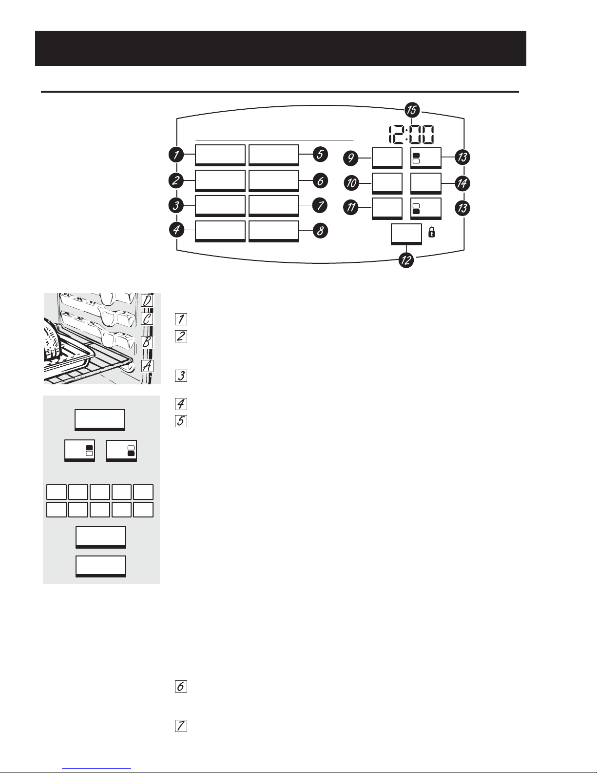
Place the food on a broiler grid in a
broiler pan.
For double oven models only,
touch UPPER OVEN or LOWER OVEN
to select the desired oven.
Follow suggested rack positions in
the Broiling Guide.
The size, weight, thickness, starting temperature
and your preference for doneness will affect
broiling times. This guide is based on meats at
refrigerator temperature.
Touch HIGH BROIL or
LOW BROIL.
Touch START.
NOTE: A cooling fan may automatically turn on
and off to cool internal parts. This is normal, and
the fan may continue to run even after the oven
is turned off.
The broiler does not need to be
preheated for most broiling. However,
foods that cook quickly, such as thin
strips of meat or fish may require a short
preheating period of 2 to 3 minutes to
allow the food surface to brown in the
same time the food takes to be cooked
throughout.
Turn the food only once during broiling.
NOTE: Broil will not work if the temperature
probe is plugged in. Never leave your probe inside
the oven during a broil cycle.
To set the second oven, select PRESS
TO MAKE LOWER OVEN SELECTIONS or
PRESS TO MAKE UPPER OVEN SELECTIONS
as needed and follow the above steps.
The set temperature may be changed by
touching CHANGE TIME-TEMP.
The settings may be cancelled by
touching CANCEL.
The timer can be set by touching
SET KITCHEN TIMER. See the Kitchen Timer
section.
When broiling is finished, touch
CANCEL.
Close the door. Always broil with
the door closed.
START
HIGH
BROIL
LOW
BROIL
OR
If your oven is connected to 208
volts, rare steaks may be broiled by
preheating the broiler and positioning
the oven rack one position higher.
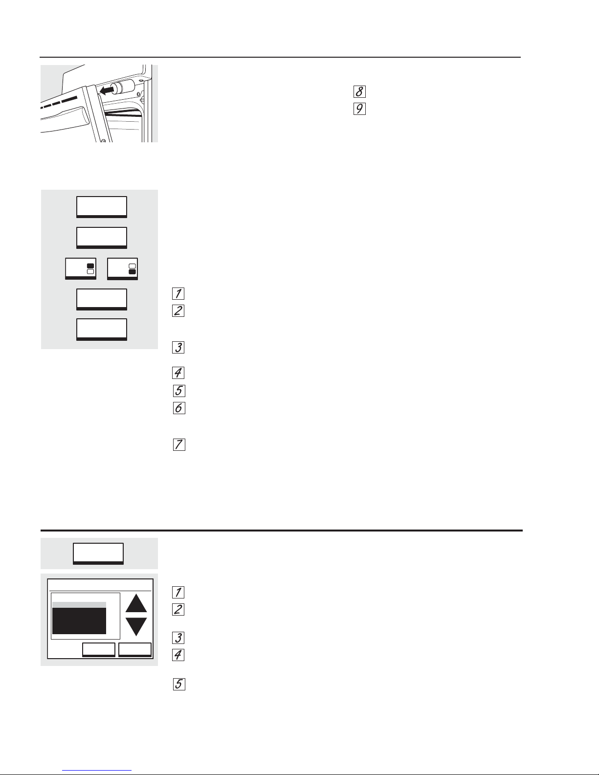
Touch CONVECTION BAKE or
CONVECTION ROAST.
For double oven models only, touch
UPPER OVEN or LOWER OVEN to
select the desired oven.
Two rack options are available:
■ SINGLE RACK – Touch for cooking
food items on only one rack in
convection bake.
■ MULTI-RACK – Touch for cooking
food items on more than one
rack (i.e. 2 or 3 racks) at the same
time in Convection Bake. See the
Multi-Rack Convection Baking section
for more information.
Touch the numbers to set the
desired temperature.
Touch ENTER.
Touch START.
The convection fan will turn on during
preheating. The control will signal when
the oven is preheated—this will take
approximately 10 minutes. The screen
will show the set temperature.
When the control signals, foods should
be placed in the oven.
For double oven models only, to set the
second oven, select PRESS TO MAKE
LOWER OVEN SELECTIONS or PRESS
TO MAKE UPPER OVEN SELECTIONS
as needed and follow the above steps.
The set temperature may be changed
by touching CHANGE TIME-TEMP for the
appropriate oven.
The settings may be cancelled by
touching CANCEL for the appropriate
oven.
The timer can be set by touching
SET KITCHEN TIMER. See the Kitchen Timer
section.
After cooking is complete, the oven will
signal and “MORE TIME” will display for
five minutes. Check food for doneness.
If more cooking time is needed, touch
MORE TIME and enter additional cooking
time. If not selected, the screen will
automatically clear.
How to Set the Oven for Convection Baking or Roasting
OR
UPPER
OVEN
LOWER
OVEN
CONVECTION
ROAST
CONVECTION
BAKE OR
On double oven models only.
START
ENTER
MULTI-RACK
SINGLE RACK OR
09876
54321

– 8 – (Continued next page)
Your control will allow you to lock out the touch
pads so they cannot be activated when touched.
NOTE: On double oven models, this activates the
feature for both ovens.
To lock/unlock the controls:
Touch the CLEAR/OFF pad for
3 seconds, until the screen shows
CONTROL LOCKED OUT.
To unlock the control, touch the
CLEAR/OFF pad for 3 seconds, until
the home screen appears.
When this feature is on and the touch
pads are touched, the control will beep
and the display will show CONTROL
LOCKED OUT.
NOTES:
■ The control lockout mode affects all controls
except for the CLEAR/OFF pad. No other
touch pad will work when this feature is
activated.
■ The adjustment will be retained in memory
after a power failure.
Control Lockout
CLEAR
OFF
Option–Proof ge.com
Proofing
The proofing feature maintains a warm
environment useful for rising yeast-leavened
products.
Place in the oven on rack B or C
and, for best results, cover the
dough with a cloth.
Touch OPTIONS.
Touch PROOF.
The oven interior light turns on and then
will cycle during proofing.
The proofing feature automatically
provides the optimum temperature for
the proofing process, and therefore does
not have a temperature adjustment.
For double oven models only, touch
UPPER OVEN or LOWER OVEN to
select the desired oven.
Touch START.
Set the KITCHEN TIMER for the
minimum proof time.
When proofing is finished, touch
CANCEL.
■Proofing will not operate when oven is above
125°F. “OVEN IS TOO HOT” will show in the
display.
■It is not necessary to preheat the oven for
proofing.
■To avoid lowering the oven temperature and
lengthening proofing time, do not open the
oven door unnecessarily.
■Check bread products early to avoid
over-proofing.
NOTE: Do not use the proofing mode to reheat
cold food or to keep hot, cooked food warm. The
proofing oven temperature is not hot enough to
hold foods at safe temperatures. Use the WARM
feature to keep hot food warm.
OR
OPTIONS
PROOF
KITCHEN
TIMER
UPPER
OVEN
LOWER
OVEN
START
CANCEL
Note: The convection fan and the lights are operating during this function.

– 9 –
Option–Two Temps
Two Temps
Use to set a first temperature with a cooking time
and also a second temperature with a second
cooking time.
Touch OPTIONS.
Touch TWO TEMPS.
For double oven models only, touch
UPPER OVEN or LOWER OVEN to
select the desired oven.
Touch the numbers to set the
desired first temperature.
Touch ENTER.
Touch the numbers to set
the desired length of the first
cooking time.
Touch ENTER.
Touch BAKE, CONVECTION BAKE or
CONVECTION ROAST as desired.
If CONVECTION BAKE was selected,
touch SINGLE RACK for one rack or
MULTI-RACK for two or three rack
cooking.
Touch the numbers to set the
desired second temperature.
Touch ENTER.
Touch the numbers to set
the desired length of the second
cooking time.
Touch ENTER.
Touch PRE-HEATED START or
COLD START.
OR
UPPER
OVEN
LOWER
OVEN
ENTER
09876
54321
09876
54321
ENTER
ENTER
09876
54321
ENTER
09876
54321
TWO
TEMPS
OR
C
ONVECTION
B
AKE
B
AKE
OR
C
ONVECTION
R
OAST
OPTIONS
PRE-HEATED
START
COLD
START
OR
MULTI-RACK
SINGLE RACK OR
On double oven models only.

– 10 –
Help
Touch this pad to find out more about your oven’s
features.
Touch the HELP pad.
Touch the ▲(up) or ▼(down)
arrow to select the desired feature.
Touch ENTER.
Touch the ▼(down) arrow, if
present, to see all of the HELP text.
Touch EXIT HELP to exit the HELP
screen.
HELP
Help Feature
ENTER EXIT
HELP
HELP
SELECT CATEGORY
BAKE
BROIL
CONVECTION BAKE
CONVECTION ROAST
KITCHEN TIMER
31
Dehydration (Drying) is a method of preserving fruits,
vegetables, herbs and meats by removing moisture so
bacteria, yeast and mold cannot grow and spoil the
food. The oven uses an automatic set temperature and
the convection fan to remove moisture from the foods
to dry and preserve them. Note that over 12 hours may
be required to dry some foods.
Accurate and complete information on basic food
drying is available from your local cooperative
extension service office. To locate this office in your
area, look in your telephone directory for the county
government listings under your county name.
During dehydration, your oven door must remain
partially open to allow for air circulation and moisture
removal.
Use the dehydration doorstop, which is included with
your oven, to hold the door open for dehydration.
Open the oven door.
Place the magnetic end of the
doorstop onto the upper inside
surface of the oven door.
Close the oven door, allowing the
door to rest against the doorstop.
Touch OPTIONS.
Touch DEHYDRATE.
For double oven models only, touch
UPPER OVEN or LOWER OVEN to
select the desired oven.
Enter the temperature
(max. 200°F)
.
Touch ENTER.
Touch START
.
NOTES:
■ Store the doorstop in a safe place when not
in use.
■ Use only the doorstop provided with your oven
and only use the doorstop while dehydrating.
■ Do not store the doorstop in the oven.
■ Remember that the proper preparation,
treatment and storage of food are essential
for the quality and safety of dried food.
Dehydrating Helpful Tips:
■ Multiple racks of food can be dried at one
time.
■ Drying time will vary depending on several
factors:
• number of racks of food
• amount of food on each rack
• size, shape and thickness of food
• type of drying trays used
■ Use food preservation resources, such as your
local cooperative extension service, as a guide
for selecting food-safe drying trays.
To order a replacement doorstop, call
our National Parts Center at 800.626.2002
and reference WB08T10024.
Dehydrate
DEHYDRATE
OPTIONS
OR
UPPER
OVEN
LOWER
OVEN
START
ENTER
29
Place the magnetic end onto the
upper inside surface of the oven door.
Close the door against the doorstop.
Note: The heat for this function is generated by the broil element. The broil
element cycles on and off to maintain the selected temperature.

– 11 –
Options–Settings
SETTINGS
TEMP
SELECTION
OPTIONS
OK
DONE
AND/OR
TEMPERATURE
OFFSET
+1˚–1˚
Note: This adjustment will only affect
baking and roasting temperatures; it
does not affect broiling, convection or
self-cleaning temperatures.
The adjustment will be retained in
memory after a power failure.
Touch1. OPTIONS.
Touch2. SETTINGS.
Touch3. TEMP SELECTIONS.
Touch4. TEMPERATURE OFFSET.
The oven temperature can be5.
adjusted up to (+) 35°F hotter or (-)
35°F cooler. Touch + 1° or - 1° to
increase or decrease the offset
temperature in 1° increments.
When you have made the6.
adjustment, touch OK and DONE.
Use your oven as you would
normally.
Note: Other adjustments controlled by
OPTIONS - SETTINGS include:
To set the Clock•
12-Hour Shut-Off•
Clock Blackout•
Sabbath Feature•
Fahrenheit to Celsius• Temperature Selection
Auto Recipe• TM Conversion
(on some models)
Language•
Display Color•
Sound On/Off•
Sound Volume•
Timer Signal•
Kitchen Timer Signal•
Sound/Volume Default•
Note: See Use & Care for detailed
procedures.
Adjust the Oven Thermostat―Do It Yourself!

– 12 –
Operational Notes
Certain modes, when selected, will automatically
enter into a preheat. The PREHEAT light will turn
on and 100°F will appear in the display. (The
temperature display will start to change once the
oven temperature reaches 100°F.)
For convection ovens, the convection fan will run
during the Single-Rack preheat cycle and remain
on until the oven has reached the set temperature.
The bake element is on for 20 seconds, then the
broil element is on for 70 seconds until preheat is
completed. After preheat, the bake element or the
broil element is cycled to maintain temperature.
Multi-Rack preheat cycle uses only the bake
element with the convection fan.
For non-convection ovens, the bake element is on
for 60 seconds, then the broil element is on for 30
seconds until preheat is completed. After preheat,
the bake element or the broil element is cycled to
maintain temperature.
The control will beep when the oven is preheated―
this may take approximately 10 minutes. The
PREHEAT light will turn off and the display will show
the set temperature.
*Preheat for Convection Roast uses only the broil
element with the convection fan. The convection
will NOT reverse directions during Convection Roast
preheat.
The convection fan will cycle on and off to•
change direction while cooking to best distribute
hot air in the oven. The convection fan shuts off
when the oven door is opened.
A cooling fan will turn on to cool internal parts.•
This is normal, and the fan may continue to run
even after the oven is turned off.
Broil will not work if the temperature probe is•
plugged in.
When using the probe, you can use the timer,•
but you cannot use timed oven operations.
On the double wall oven, the oven control will•
automatically set the oven that has the probe
plugged into it.
In Convection Bake, the bake element and the•
fan operate whenever the oven is preheating.
On the double wall oven, you can use timed•
baking in both ovens at the same time.
The Clean cycle can be set for a minimum of 3•
hours and a maximum of 5 hours. The default
setting is 5 hours. The 5-hour set time consists
of 4 hours and 20 minutes of cleaning and 40
minutes of cool down. The door will unlock at an
approximate temperature of 450°F.
On the double wall oven, you can set a clean•
cycle in both ovens at the same time. The last
oven set will automatically delay its start until
the first oven's clean cycle cools to 400°F. On
the double wall oven, you can bake or broil in
one oven and self-clean in the other at the same
time.
Self-Clean will not work if the temperature probe•
is plugged in or if the Sabbath feature is set.
Proofing will not operate when oven is above•
125°F. The display will show “too hot”. Allow the
oven time to cool. During Proof, the oven light is
on continuously. The convection fan will operate
60 seconds in one direction, 60 seconds in the
other direction, then off for 600 seconds.
In Warm, found under options, the broil and the•
bake elements are used to reach these target
temperatures: Low = 160°F; Medium = 180°F;
and High = 195°F. These temperatures are all
±15°F. The convection fan runs in the "crisp"
mode and does not run in the "moist" mode.
Preheat Chart
Mode Preheat
Proof No
Dehydrate No
Bake Yes
Convection Bake - 1 Rack Yes
Convection Bake - Multi Yes
Convection Roast* Yes
Convection Broil No
Broil High No
Broil Low No
Clean No
Probe Usage No
Sales Mode
The oven control can be operated in SALES MODE.
When the unit is connected to 120 VAC from L1–N,
the control will function normally. The 240 VAC
relays will not function.

– 13 –
Component Locator Views
Wall Oven (Single Oven shown)
(Continued next page)
Control Panel
Oven Door
Broil Element
Oven Door Gasket
Meat Probe Outlet
Convection Fan
Hidden Bake Element
Door Lock
Oven Temperature Sensor
2 Lights
Control Compartment
Bottom Double Wall Oven (Middle Trim Assembly Shown Removed)
Note: Bake FAD Thermal
and Cooling Fan are
located behind Vent Tube.
Door Lock
Vent Tube
Clean FAD Thermal Relay Board

– 14 –
Control Compartment
Top of Oven (Single Oven and Top Double Oven)
(Continued next page)
Cooling Fan Power Supply
Board
Door Lock
LCD Control Board
Door Switch Relay Board
Clean FAD Thermal
Cooling Fan
Convection Fan
Bake FAD Thermal
Convection Element
Capacitor
Back of Single Oven (All Rear Covers Shown Removed)
Bake Element
Broil Element
Thermal Limit Switch

– 15 –
Oven Component Access Chart
WARNING:
The single and double wall ovens are heavy and require two people to remove them from the installation.•
Care should be taken when removing and installing.
Sharp edges may be exposed when servicing. Use caution to avoid injury. Wear Kevlar gloves or•
equivalent protection.
Bake Element zzz z
Broil Element zzzz
Convection Bake Element zzzz
Convection Fan Blade zzzz
Convection Fan Capacitor zzz z
Convection Fan Motor zzz z
Control Panel Assembly zz
n/a z
Cooling Fans zzz z
Door Assembly zzzz
Door Switch zzzz
Door Hinge Receiver zzz z
Lock Assembly zzzz
Meat Probe Outlet zzzz
Oven Light Assembly zzzz
Oven Temperature Sensor zzzz
Power Supply Board zzzz
Relay Boards zzzz
Thermal Switch (Limit Thermal
Switch)
zzz z
Thermal Switch (Bake FAD) zzz z
Thermal Switch (Clean FAD) zzzz
Vent Tube/Smoke Eliminator zzzz
Single
Double Upper
Double Lower
Front Serviceable Oven Components
Components Requiring Oven Removal

– 16 –
Door Assembly
The oven door can be separated into 2 assemblies.
The outer assembly consists of the outer panel
and a replaceable door handle. The inner assembly
is made up of the inner panel, door gasket, 3
glass panels, air channel, insulation retainer, and
replaceable door hinge assemblies.
Caution: The door is very heavy. Use the correct
lifting procedure. Do not lift the door by the handle.
To remove the door:
Open the door fully. Pull the hinge locks down1.
toward the door frame, to the unlocked position.
(This may require a flat-blade screwdriver to
start the hinge locks moving).
To replace the door:
With the door at the same angle as the removal1.
position, seat the indentation of the hinge arm
into the bottom edge of the hinge slot. The
notch in the hinge arm must be fully seated into
the bottom of the slot.
Firmly grasp both sides of the door at the top.2.
Close the door to the door removal position,3.
then lift it up and out.
Oven Components
(Continued next page)
Open the door fully. If the door will not fully2.
open, the indentation is not seated correctly in
the bottom edge of the slot.
Push the hinge locks up against the front frame3.
of the oven cavity to the locked position.
Indentation
Bottom
Edge of
Slot
Hinge
Arm
Hinge Arm
Push hinge locks up to lock
Hinge
Lock
Removal position
Hinge Lock
Slot
Close the oven door and check for proper4.
alignment.

– 17 –
To replace the inner door assembly:
Remove the outer door assembly. (See1. Door
Assembly.)
2. Remove the four T15 Torx screws (2 on each
side) that attach each door hinge to the inner
door. Carefully turn the door over and remove
both door hinges.
Remove the four 1/4-in. hex-head screws that3.
attach the glass and side brackets (glass closest
to the outer door glass) to the inner door.
Remove the two T15 Torx screws (1 on each4.
side) from the inner door assembly.
Caution: Care must be taken if reinstalling the door
handle. Overtightening the screws can damage the
handle. Hand-tighten the screws and make sure
the handle fits snugly to the door panel. (Do not use
electric driver.)
(Continued next page)
To remove the outer door assembly:
Remove the door.1.
Place the inner door assembly, gasket side up,2.
on a protective surface.
Remove the four 1/4-in. hex-head screws from3.
the bottom of the outer door assembly.
Note: The inner door assembly is heavier than the
outer door assembly.
Separate the inner door assembly from the5.
outer door assembly.
Remove the two 1/4-in. hex-head screws and6.
brackets that hold the door handle to the outer
door assembly.
Door Shown with Inner Door Assembly Removed
Outer Door Assembly

– 18 –
Remove the six 1/4-in. hex-head screws that4.
hold the heat barrier to the inner door. Remove
the barrier.
Remove the insulation and the inner glass5.
assembly from the inner door.
OVEN
Assembly Notes
When assembling the door assembly, make sure the
hinges are parallel to each other and perpendicular
to the door liner. If not, the hinge may bind on the
receiving channel of the door. If the new hinge is not
in the cocked and locked position after installing,
place the bottom of the door against a firm,
protected surface and push the hinge arm down
to the cocked position. Pull the hinge lock back
against the door liner surface to lock the hinge in
this position.
Air enters the door assembly through large slots in
the bottom and flows upward between the inner
and outer assemblies, exhausting through slots
in the top of the door. DO NOT INSULATE THIS AIR
CHANNEL.
Arrows on the side of the inner glass assembly
indicate the direction in which the inner oven door
glass is installed. The arrows should be pointing
toward the oven cavity.
Door Gasket
The gasket forms a complete seal around the front
edge of the oven liner and the inner door panel. The
door gasket is attached to the inner door panel by
spring clips. When removing the gasket, pull the
ends of the gasket out of the slots at the bottom
of the door. Place a finger under the gasket beside
each clip and pull straight up.
When installing the door gasket, it is helpful to fold
the gasket in half and locate the center clip. Insert
the clip at the top of the door and work your way
around the door.
Make sure the gasket is cross-tucked in the
bottom slots of the inner door panel. Use a small
screwdriver to tuck the loose ends of the gasket into
the slots. The overlap is required to ensure a proper
door seal.
Inner Glass Assembly
Cross Tuck

– 19 –
Oven Removal
The replacement of certain components require
oven removal. (See Oven Component Access Chart.)
WARNING: The oven is heavy and requires two
people to remove it from the installation.
Note: Sharp edges may be exposed when servicing.
Use caution to avoid injury. Wear Kevlar gloves or
equivalent protection.
To remove the oven:
Disconnect power to the oven.1.
Remove oven doors and racks. (See2. Door
Assembly.)
Remove the 4 Phillips-head screws (2 on each3.
side) from the side trims that hold the oven in
place. (There are 8 Phillips-head screws on the
double oven.)
Utilize a table or platform in front of the oven4.
and pull the oven completely out.
Note: When reinserting ovens into cabinet opening,
ensure conduit is properly positioned behind ovens.
(See the Installation Instructions manual.)
Control Compartment Access
It may be necessary to remove the oven from the
installation to gain access to some components.
(See Component Access Chart.)
Note: The glass touch boards and the control panel
front are one unit and are ordered as an assembly.
To access the control compartment on single or
double ovens:
Open oven door.1.
Remove the three 1/4-in. hex-head screws that2.
attach the bottom of the control panel to the
vent trim.
Place a cardboard protector on top of the oven3.
door and close the door.
Note: The control panel has keyhole slots at the top
and is held very tight to the side trims.
4. Carefully push the control panel up, then pull out
at the bottom.
5. Place the control panel on a protected oven
door as shown.
Note: When installing the control panel, make sure
the bottom edge of the control panel sits on top of
the metal air divider and vent trim.
Keyhole Slot Keyhole Slot

– 20 –
Lower Oven Control Compartment Access
Note: It may be necessary to remove the oven from
the installation to gain access to some components.
(See Component Access Chart.)
To access the lower oven control compartment:
Remove the upper oven door. (See1. Door
Assembly.)
Remove the 2 Phillips-head screws from the top2.
of the middle trim.
Open the lower oven door.3.
Remove the three 1/4-in. hex-head screws from4.
the bottom of the middle trim. Remove the trim.
Remove the four 1/4-in. hex-head screws5.
that attach the cross member to the front
of the control compartment. Remove the
crossmember.
Screws
Middle Trim
Top Access Panels
Removing the top access panels permits access to
the control compartment, cooling fan, and the bake
FAD thermal.
The oven must be removed to access the 1/4-in.
hex-head screws that attach the top panels. (See
Oven Removal.)
The front top access panel has 5 hex-head screws.
The rear top access panel has 8 hex-head screws.
Remove the two 1/4-in. hex-head screws from6.
the relay board tray.
Remove the four 1/4-in. hex-head screws (one7.
under the relay board) that attach the vent trim
to the front of the cabinet. Remove the trim.
Other manuals for Profile PT920
4
This manual suits for next models
1
Table of contents
Other GE Oven manuals

GE
GE JCB865 User manual

GE
GE JKS05 Series User manual

GE
GE Advantium SCA2000 User manual

GE
GE Monogram Advantium ZSC1001KSS Manual

GE
GE Profile PT960SMSS Manual

GE
GE RGJ515GEH Installation instructions

GE
GE JTP70DPBB Manual

GE
GE JKP90BM4BB User manual

GE
GE Trivection JT930 User manual

GE
GE JKS5000 User manual