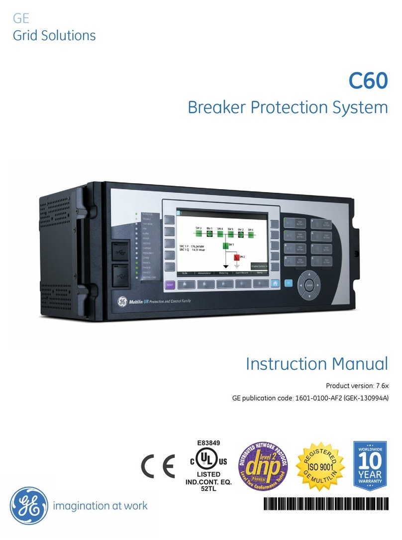
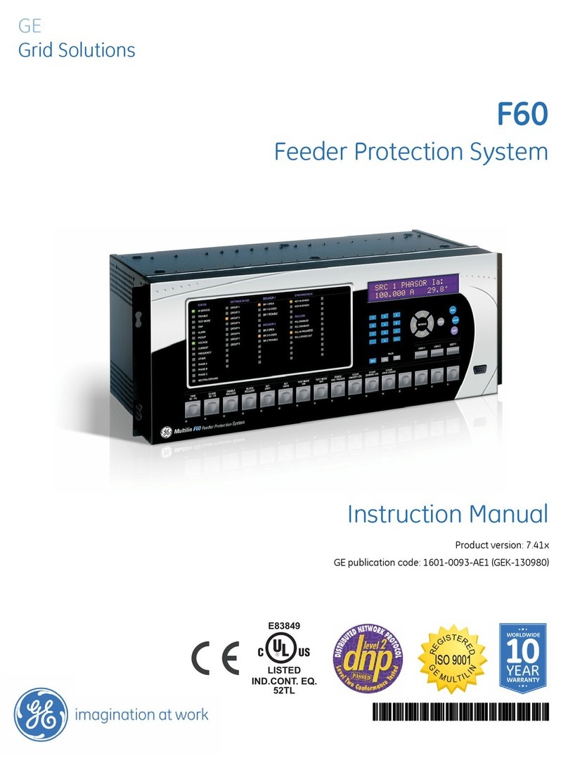
GE 345 Use and care manual

Title page
GE Multilin's Quality
Management System is
registered to ISO9001:2000
QMI # 005094
GE Digital Energy
Multilin
GE Multilin
215 Anderson Avenue, Markham, Ontario
Canada L6E 1B3
Tel: (905) 294-6222 Fax: (905) 201-2098
Internet: http://www.GEmultilin.com
Communications Guide
SR345 revision: 1.30
Manual P/N: 1601-9099-A1
GE publication code: GEK-113570
Copyright © 2010 GE Multilin
*1601-xxxx-A3*
345
Transformer Protection System
Transformer protection and control

© 2010 GE Multilin Incorporated. All rights reserved.
GE Multilin SR345 Transformer Protection System Communications Guide for revision 1.30.
SR345 Transformer Protection System, EnerVista, EnerVista Launchpad, and EnerVista SR3
Setup, are registered trademarks of GE Multilin Inc.
The contents of this manual are the property of GE Multilin Inc. This documentation is
furnished on license and may not be reproduced in whole or in part without the permission
of GE Multilin. The content of this manual is for informational use only and is subject to
change without notice.
Part number: 1601-9099-A1 (February 2010)

TOC
345 TRANSFORMER PROTECTION SYSTEM – COMMUNICATIONS GUIDE toc–1
Table of Contents
Communications interfaces ...................................................................................... 1
RS485 interface............................................................................................................ 2
Electrical Interface ...........................................................................................................................................2
MODBUS Protocol.............................................................................................................................................2
Data Frame Format and Data Rate ........................................................................................................ 2
Data Packet Format ....................................................................................................................................... 3
Error Checking................................................................................................................................................... 3
CRC-16 Algorithm ............................................................................................................................................ 3
Timing.................................................................................................................................................................... 4
345 supported functions.............................................................................................................................. 4
DNP protocol settings.....................................................................................................................................5
DNP communication...................................................................................................................................... 5
DNP device profile ........................................................................................................................................... 6
DNP implementation...................................................................................................................................... 8
DNP serial EnerVista Setup........................................................................................................................13
DNP general .....................................................................................................................................................15
IEC 60870-5-103 serial communication.............................................................................................16
Interoperability ...............................................................................................................................................16
Physical layer...................................................................................................................................................16
Link layer ........................................................................................................................................................... 17
Application layer ............................................................................................................................................17
Transmission mode for application data............................................................................................17
Common address of ASDU........................................................................................................................17
Selection of standard information numbers in monitor direction..........................................17
Selection of standard information numbers in control direction............................................20
Basic application functions.......................................................................................................................20
Miscellaneous..................................................................................................................................................21
Application level.............................................................................................................................................21
Application functions ...................................................................................................................................21
Type identification.........................................................................................................................................21
Function type...................................................................................................................................................22
Information number.....................................................................................................................................22
Data management .......................................................................................................................................22
Digital states ....................................................................................................................................................23
Measurands......................................................................................................................................................23
Commands.......................................................................................................................................................24
103 general settings ....................................................................................................................................25
Ethernet interface .....................................................................................................26
SNTP..................................................................................................................................................................... 26
SNTP settings...................................................................................................................................................26
SNTP modes .....................................................................................................................................................26
MODBUS TCP/IP.............................................................................................................................................. 27
Data and control functions .......................................................................................................................27
Exception and error responses ...............................................................................................................35
Request response sequence ....................................................................................................................35
CRC .......................................................................................................................................................................36
DNP Ethernet protocol settings .............................................................................................................. 38
DNP communication....................................................................................................................................38
DNP device profile .........................................................................................................................................38
DNP port allocation.......................................................................................................................................41
DNP implementation....................................................................................................................................42
DNP Ethernet EnerVista Setup.................................................................................................................47
DNP general .....................................................................................................................................................49
IEC60870-5-104 protocol .......................................................................................................................... 50
IEC 60870-5-104 interoperability...........................................................................................................50

toc–2 345 TRANSFORMER PROTECTION SYSTEM – COMMUNICATIONS GUIDE
TOC
IEC 60870-5-104 protocol settings........................................................................................................58
IEC 60870-5-104 point lists .......................................................................................................................58
Summary of Ethernet client connections...........................................................................................60
IEC 61850 GOOSE communications......................................................................................................62
EnerVista SR3 Setup software structure.............................................................................................62
GOOSE transmission.....................................................................................................................................64
GOOSE Rx...........................................................................................................................................................65
GOOSE Rx status ............................................................................................................................................66
GOOSE Rx headers ........................................................................................................................................67
GOOSE receive dataset structure...........................................................................................................68
GOOSE remote inputs ..................................................................................................................................69
USB interface..............................................................................................................72
MODBUS Protocol ..........................................................................................................................................72
Data Frame Format and Data Rate ......................................................................................................72
Data Packet Format......................................................................................................................................72
Error Checking.................................................................................................................................................73
CRC-16 Algorithm ..........................................................................................................................................73
Timing..................................................................................................................................................................74
345 supported functions ............................................................................................................................74
MODBUS memory map.............................................................................................75
Format Codes ...............................................................................................................................................128
MODBUS Functions ................................................................................................ 171
Function Code 03H.....................................................................................................................................171
Function Code 04H.....................................................................................................................................171
Function Code 05H.....................................................................................................................................172
Function Code 06H.....................................................................................................................................173
Function Code 07H.....................................................................................................................................173
Function Code 08H.....................................................................................................................................174
Function Code 10H.....................................................................................................................................175
Error Responses...........................................................................................................................................175
Force coil commands................................................................................................................................176
Performing Commands Using Function Code 10H.....................................................................177
Using the MODBUS User Map............................................................................... 179
MODBUS User Map.....................................................................................................................................179

345 TRANSFORMER PROTECTION SYSTEM – COMMUNICATIONS GUIDE 1–1
345 Transformer Protection System
Communications Guide
Digital Energy
Multilin
Communicatio ns Guide
Communications interfaces
The 345 has three communications interfaces. These can be used simultaneously:
• RS485
•USB
•Ethernet

1–2 345 TRANSFORMER PROTECTION SYSTEM – COMMUNICATIONS GUIDE
RS485 INTERFACE CHAPTER 1: COMMUNICATIONS GUIDE
RS485 interface
The hardware or electrical interface in the 345 is two-wire RS485. In a two-wire link, data is
transmitted and received over the same two wires. Although RS485 two wire
communication is bi-directional, the data is never transmitted and received at the same
time. This means that the data flow is half duplex.
NOTE
NOTE: Polarity is important in RS485 communications. The '+' (positive) terminals of every device
must be connected together.
Electrical Interface
The hardware or electrical interface in the 345 is two-wire RS485. In a two-wire link, data is
transmitted and received over the same two wires. Although RS485 two wire
communication is bi-directional, the data is never transmitted and received at the same
time. This means that the data flow is half duplex.
RS485 lines should be connected in a daisy chain configuration with terminating networks
installed at each end of the link (i.e. at the master end and at the slave farthest from the
master). The terminating network should consist of a 120 W resistor in series with a 1 nF
ceramic capacitor when used with Belden 9841 RS485 wire. Shielded wire should always
be used to minimize noise. The shield should be connected to all of the 345s as well as the
master, then grounded at one location only. This keeps the ground potential at the same
level for all of the devices on the serial link.
NOTE
NOTE: Polarity is important in RS485 communications. The '+' (positive) terminals of every device
must be connected together.
MODBUS Protocol
The 345 implements a subset of the Modicon Modbus RTU serial communication standard.
The Modbus protocol is hardware-independent. That is, the physical layer can be any of a
variety of standard hardware configurations. This includes USB, RS485, fibre optics, etc.
Modbus is a single master / multiple slave type of protocol suitable for a multi-drop
configuration.
The 345 is always a Modbus slave. It can not be programmed as a Modbus master.
Computers or PLCs are commonly programmed as masters.
Both monitoring and control are possible using read and write register commands. Other
commands are supported to provide additional functions.
The Modbus protocol has the following characteristics.
•Address:1to254
• Supported Modbus function codes: 3, 4, 5, 6, 7, 8, 10
Data Frame Format
and Data Rate
One data frame of an asynchronous transmission to or from a 345 typically consists of 1
start bit, 8 data bits, and 1 stop bit. This produces a 10 bit data frame. This is important for
transmission through modems at high bit rates.
Modbus protocol can be implemented at any standard communication speed. The 345
supports operation at 9600, 19200, 38400, 57600, and 115200 baud.

CHAPTER 1: COMMUNICATIONS GUIDE RS485 INTERFACE
345 TRANSFORMER PROTECTION SYSTEM – COMMUNICATIONS GUIDE 1–3
Data Packet Format A complete request/response sequence consists of the following bytes (transmitted as
separate data frames):
Master Request Transmission:
SLAVE ADDRESS: 1 byte
FUNCTION CODE: 1 byte
DATA: variable number of bytes depending on FUNCTION CODE
CRC: 2 bytes
Slave Response Transmission:
SLAVE ADDRESS: 1 byte
FUNCTION CODE: 1 byte
DATA: variable number of bytes depending on FUNCTION CODE
CRC: 2 bytes
SLAVE ADDRESS: This is the first byte of every transmission. This byte represents the user-
assigned address of the slave device that is to receive the message sent by the master.
Each slave device must be assigned a unique address and only the addressed slave will
respond to a transmission that starts with its address. In a master request transmission the
SLAVE ADDRESS represents the address of the slave to which the request is being sent. In a
slave response transmission the SLAVE ADDRESS represents the address of the slave that is
sending the response.
FUNCTION CODE: This is the second byte of every transmission. Modbus defines function
codes of 1 to 127.
DATA: This will be a variable number of bytes depending on the FUNCTION CODE. This may
be Actual Values, Setpoints, or addresses sent by the master to the slave or by the slave to
the master.
CRC: This is a two byte error checking code.
Error Checking The RTU version of Modbus includes a two byte CRC-16 (16 bit cyclic redundancy check)
with every transmission. The CRC-16 algorithm essentially treats the entire data stream
(data bits only; start, stop and parity ignored) as one continuous binary number. This
number is first shifted left 16 bits and then divided by a characteristic polynomial
(11000000000000101B). The 16 bit remainder of the division is appended to the end of the
transmission, MSByte first. The resulting message including CRC, when divided by the
same polynomial at the receiver will give a zero remainder if no transmission errors have
occurred.
If a 345 Modbus slave device receives a transmission in which an error is indicated by the
CRC-16 calculation, the slave device will not respond to the transmission. A CRC-16 error
indicates than one or more bytes of the transmission were received incorrectly and thus
the entire transmission should be ignored in order to avoid the 345 performing any
incorrect operation.
The CRC-16 calculation is an industry standard method used for error detection. An
algorithm is included here to assist programmers in situations where no standard CRC-16
calculation routines are available.
CRC-16 Algorithm Once the following algorithm is complete, the working register “A” will contain the CRC
value to be transmitted. Note that this algorithm requires the characteristic polynomial to
be reverse bit ordered. The MSBit of the characteristic polynomial is dropped since it does
not affect the value of the remainder. The following symbols are used in the algorithm:
—>: data transfer
A: 16 bit working register
AL: low order byte of A
AH: high order byte of A
CRC: 16 bit CRC-16 value

1–4 345 TRANSFORMER PROTECTION SYSTEM – COMMUNICATIONS GUIDE
RS485 INTERFACE CHAPTER 1: COMMUNICATIONS GUIDE
i, j: loop counters
(+): logical exclusive or operator
Di: i-th data byte (i = 0 to N-1)
G: 16 bit characteristic polynomial = 1010000000000001 with MSbit dropped and bit order
reversed
shr(x): shift right (the LSbit of the low order byte of x shifts into a carry flag, a '0' is shifted
into the MSbit of the high order byte of x, all other bits shift right one location
The algorithm is:
1. FFFF hex —> A
2. 0 —> i
3. 0 —> j
4. Di (+) AL —> AL
5. j+1 —> j
6. shr(A)
7. is there a carry? No: go to 8. Yes: G (+) A —> A
8. is j = 8? No: go to 5. Yes: go to 9.
9. i+1 —> i
10. is i = N? No: go to 3. Yes: go to 11.
11. A —> CRC
Timing Data packet synchronization is maintained by timing constraints. The receiving device
must measure the time between the reception of characters. If 3.5 character times elapse
without a new character or completion of the packet, then the communication link must
be reset (i.e. all slaves start listening for a new transmission from the master). Thus at 9600
baud a delay of greater than 3.5 x 1 / 9600 x 10 x = x 3.65 x ms will cause the
communication link to be reset.
345 supported
functions
The following functions are supported by the 345:
• FUNCTION CODE 03 - Read Setpoints
• FUNCTION CODE 04 - Read Actual Values
• FUNCTION CODE 05 - Execute Operation
• FUNCTION CODE 06 - Store Single Setpoint
• FUNCTION CODE 07 - Read Device Status
• FUNCTION CODE 08 - Loopback Test
• FUNCTION CODE 10 - Store Multiple Setpoints
Refer to section 5 of this guide for more details on MODBUS function codes.

CHAPTER 1: COMMUNICATIONS GUIDE RS485 INTERFACE
345 TRANSFORMER PROTECTION SYSTEM – COMMUNICATIONS GUIDE 1–5
DNP protocol settings
DNP communication The menu structure for the DNP protocol is shown below.
The following path is available using the keypad. For instructions on how to use the
keypad, please refer to Chapter 3 - Working with the Keypad.
PATH: SETPOINTS > RELAY SETUP > COMMUNICATIONS > DNP PROTOCOL > DNP GENERAL
S1 DNP GENERAL
DNP ADDRESS
DNP TCP/UDP PORT
CHANNEL 1 PORT
CHANNEL 2 PORT
TME SYNC IIN PER.
DNP MSG FRAG SIZE
DNP TCP CONN. T/O
▼
S1 DNP
DNP GENERAL
DNP UNSOL RESPONSE*
DEFAULT VARIATION
DNP CLIENT ADDRESS*
DNP POINTS LIST
897769.cdr
DNP CLIENT ADDRESS*
CLIENT ADDRESS 1
CLIENT ADDRESS 2
CLIENT ADDRESS 3
CLIENT ADDRESS 4
CLIENT ADDRESS 5
POINT 0
...
POINT 1
POINT 2
POINT 63
▼
S1 DNP POINTS LIST
BINARY INPUTS
BINARY OUTPUT
ANALOG INPUTS
POINT 0 ENTRY
...
POINT 1 ENTRY
POINT 31 ENTRY
▼
POINT 0 ON
...
POINT 0 OFF
POINT 1 ON
POINT 1 OFF
POINT 15 ON
POINT 15 OFF
▼
DEFAULT VARIATION
DNP OBJECT 1
DNP OBJECT 2
DNP OBJECT 20
DNP OBJECT 21
DNP OBJECT 22
DNP OBJECT 23
DNP OBJECT 30
DNP OBJECT 32
DNP UNSOL RESPONSE*
FUNCTION
▼
TIMEOUT
MAX RETRIES
DEST ADDRESS
* Ethernet only

1–6 345 TRANSFORMER PROTECTION SYSTEM – COMMUNICATIONS GUIDE
RS485 INTERFACE CHAPTER 1: COMMUNICATIONS GUIDE
DNP device profile
DNP 3.0 Device Profile
(Also see the IMPLEMENTATION TABLE in the following section)
Vendor Name: General Electric Multilin
Device Name: SR345 Relay
Highest DNP Level Supported:
For Requests: Level 2
For Responses: Level 2
Device Function:
□Master
⊠Slave
Notable objects, functions, and/or qualifiers supported in addition to the Highest DNP Levels
Supported (the complete list is described in the attached table):
Binary Inputs (Object 1)
Binary Input Changes (Object 2)
Binary Outputs (Object 10)
Control Relay Output Block (Object 12)
Binary Counters (Object 20)
Frozen Counters (Object 21)
Counter Change Event (Object 22)
Frozen Counter Event (Object 23)
Analog Inputs (Object 30)
Analog Input Changes (Object 32)
Analog Deadbands (Object 34)
Time and Date (Object 50)
Internal Indications (Object 80)
Maximum Data Link Frame Size (octets): Maximum Application Fragment Size (octets):
Transmitted: 292 Transmitted: configurable up to 2048
Received: 292 Received: 2048
Maximum Data Link Re-tries: Maximum Application Layer Re-tries:
⊠None ⊠None
□Fixed at 3 □Configurable
□Configurable
Requires Data Link Layer Confirmation:
⊠Never
□Always
□Sometimes
□Configurable
Requires Application Layer Confirmation:
□Never
□Always

CHAPTER 1: COMMUNICATIONS GUIDE RS485 INTERFACE
345 TRANSFORMER PROTECTION SYSTEM – COMMUNICATIONS GUIDE 1–7
⊠When reporting Event Data
⊠When sending multi-fragment responses
□Sometimes
□Configurable
Timeouts while waiting for:
Data Link Confirm: ⊠None □Fixed □Variable □Configurable
Complete Appl. Fragment: ⊠None □Fixed □Variable □Configurable
Application Confirm: □None ⊠Fixed at 10 s □Variable □Configurable
Complete Appl. Response: ⊠None □Fixed at ___ □Variable □Configurable
Others:
Transmission Delay: No intentional delay
Need Time Interval: Configurable (default = 24 hrs.)
Select/Operate Arm Timeout: 10 s
Binary input change scanning period: 8 times per power system cycle
Analog input change scanning period: 500 ms
Counter change scanning period: 500 ms
Frozen counter event scanning period: 500 ms
Sends/Executes Control Operations:
WRITE Binary Outputs ⊠Never □Always □Sometimes □Configurable
SELECT/OPERATE □Never ⊠Always □Sometimes □Configurable
DIRECT OPERATE □Never ⊠Always □Sometimes □Configurable
DIRECT OPERATE – NO ACK □Never ⊠Always □Sometimes □Configurable
Count > 1 ⊠Never □Always □Sometimes □Configurable
Pulse On □Never □Always ⊠Sometimes □Configurable
Pulse Off □Never □Always ⊠Sometimes □Configurable
Latch On □Never □Always ⊠Sometimes □Configurable
Latch Off □Never □Always ⊠Sometimes □Configurable
Queue ⊠Never □Always □Sometimes □Configurable
Clear Queue ⊠Never □Always □Sometimes □Configurable
Explanation of ‘Sometimes’: Object 12 points are mapped to Virtual Inputs. Both “Pulse On” and
“Latch On” operations perform the same function in the 345; that is, the appropriate Virtual Input is
put into the “On” state. The On/Off times and Count value are ignored. “Pulse Off” and “Latch Off”
operations put the appropriate Virtual Input into the “Off” state.
Reports Binary Input Change Events when no
specific variation requested:
Reports time-tagged Binary Input Change
Events when no specific variation
requested:
□Never □Never
⊠Only time-tagged ⊠Binary Input Change With Time
□Only non-time-tagged □Binary Input Change With Relative Time
□Configurable □Configurable (attach explanation)
Sends Unsolicited Responses: Sends Static Data in Unsolicited Responses:
□Never ⊠Never
□Configurable □When Device Restarts
□Only certain objects □When Status Flags Change
⊠Sometimes No other options are permitted.
⊠ENABLE/DISABLE unsolicited Function codes
supported
DNP 3.0 Device Profile

1–8 345 TRANSFORMER PROTECTION SYSTEM – COMMUNICATIONS GUIDE
RS485 INTERFACE CHAPTER 1: COMMUNICATIONS GUIDE
DNP implementation Table 1: DNP Implementation
Explanation of ‘Sometimes’: It will be disabled for
RS-485 applications, since there is no collision
avoidance mechanism. For Ethernet communication
it will be available and it can be disabled or enabled
with the proper function code.
Default Counter Object/Variation: Counters Roll Over at:
□No Counters Reported □No Counters Reported
□Configurable (attach explanation) □Configurable (attach explanation)
⊠Default Object: 20 ⊠16 Bits
Default Variation: 1
⊠Point-by-point list attached □Other Value: _____
⊠Point-by-point list attached
Sends Multi-Fragment Responses:
⊠Yes
□No
DNP 3.0 Device Profile
OBJECT REQUEST RESPONSE
OBJECT
NO.
VARIATION
NO.
DESCRIPTION FUNCTION
CODES
(DEC)
QUALIFIER CODES
(HEX)
FUNCTION
CODES
(DEC)
QUALIFIER
CODES
(HEX)
1 0 Binary Input (Variation 0
is used to request
default variation)
1 (read) 22
(assign
class)
00, 01 (start-stop)
06 (no range, or all)
07, 08 (limited
quantity) 17, 28
(index)
--- ---
1 Binary Input 1 (read) 22
(assign
class)
00, 01 (start-stop)
06 (no range, or all)
07, 08 (limited
quantity) 17, 28
(index)
129
(response)
00, 01
(start-stop)
17, 28
(index) (see
Note 2)
2 Binary Input with Status 1 (read) 22
(assign
class)
00, 01 (start-stop)
06 (no range, or all)
07, 08 (limited
quantity) 17, 28
(index)
129
(response) 00, 01
(start-stop)
17, 28
(index) (see
Note 2)
2 0 Binary Input Change
(Variation 0 is used to
request default
variation)
1 (read) 06 (no range, or all)
07, 08 (limited
quantity)
--- ---
1 Binary Input Change
without Time 1 (read) 06 (no range, or all)
07, 08 (limited
quantity)
129
(response)
130 (unsol.
resp.)
17, 28
(index)
2 Binary Input Change
with Time 1 (read) 06 (no range, or all)
07, 08 (limited
quantity)
129
(response)
130 (unsol.
resp.)
17, 28
(index)
3 Binary Input Change
with Relative Time 1 (read) 06 (no range, or all)
07, 08 (limited
quantity)
--- ---
10 0 Binary Output Status
(Variation 0 is used to
request default
variation)
1 (read) 00, 01(start-stop)
06 (no range, or all)
07, 08 (limited
quantity) 17, 28
(index)
--- ---

CHAPTER 1: COMMUNICATIONS GUIDE RS485 INTERFACE
345 TRANSFORMER PROTECTION SYSTEM – COMMUNICATIONS GUIDE 1–9
2 Binary Output Status 1 (read) 00, 01 (start-stop)
06 (no range, or all)
07, 08 (limited
quantity) 17, 28
(index)
129
(response) 00, 01
(start-stop)
17, 28
(index) (see
Note 2)
12 1 Control Relay Output
Block
3 (select)4
(operate) 5
(direct op) 6
(dir. op,
noack)
00, 01 (start-stop)
07, 08 (limited
quantity) 17, 28
(index)
129
(response)
echo of
request
20 0 Binary Counter
(Variation 0 is used to
request default
variation)
1 (read) 7
(freeze) 8
(freeze
noack) 9
(freeze clear)
10 (frz. cl.
noack) 22
(assign
class)
00, 01 (start-stop)
06 (no range, or all)
07, 08 (limited
quantity) 17, 28
(index)
--- ---
1 32-Bit Binary Counter 1 (read)7
(freeze) 8
(freeze
noack) 9
(freezeclear)
10 (frz. cl.
noack) 22
(assign
class)
00, 01 (start-stop)
06 (no range, or all)
07, 08 (limited
quantity) 17, 28
(index)
129
(response)
00, 01
(start-stop)
17, 28
(index) (see
Note 2)
2 16-Bit Binary Counter 1 (read) 7
(freeze) 8
(freeze
noack) 9
(freezeclear)
10 (frz. cl.
noack) 22
(assign
class)
00, 01 (start-stop)
06 (no range, or all)
07, 08 (limited
quantity) 17, 28
(index)
129
(response) 00, 01
(start-stop)
17, 28
(index) (see
Note 2)
5 32-Bit Binary Counter
without Flag
1 (read) 7
(freeze) 8
(freeze
noack) 9
(freezeclear)
10 (frz. cl.
noack) 22
(assign
class)
00, 01 (start-stop)
06 (no range, or all)
07, 08 (limited
quantity) 17, 28
(index)
129
(response)
00, 01
(start-stop)
17, 28
(index) (see
Note 2)
6 16-Bit Binary Counter
without Flag 1 (read) 7
(freeze) 8
(freeze
noack) 9
(freezeclear)
10 (frz. cl.
noack) 22
(assign
class)
00, 01 (start-stop)
06 (no range, or all)
07, 08 (limited
quantity) 17, 28
(index)
129
(response) 00, 01
(start-stop)
17, 28
(index) (see
Note 2)
21 0 Frozen
Counter(Variation 0 is
used to request
defaultvariation)
1 (read) 22
(assign
class)
00, 01 (start-stop)
06 (no range, or all)
07, 08 (limited
quantity) 17, 28
(index)
--- ---
1 32-Bit Frozen Counter 1 (read) 22
(assign
class)
00, 01 (start-stop)
06 (no range, or all)
07, 08 (limited
quantity) 17, 28
(index)
129
(response) 00, 01
(start-stop)
17, 28
(index) (see
Note 2)
OBJECT REQUEST RESPONSE
OBJECT
NO.
VARIATION
NO.
DESCRIPTION FUNCTION
CODES
(DEC)
QUALIFIER CODES
(HEX)
FUNCTION
CODES
(DEC)
QUALIFIER
CODES
(HEX)

1–10 345 TRANSFORMER PROTECTION SYSTEM – COMMUNICATIONS GUIDE
RS485 INTERFACE CHAPTER 1: COMMUNICATIONS GUIDE
2 16-Bit Frozen Counter 1 (read) 22
(assign
class)
00, 01 (start-stop)
06 (no range, or all)
07, 08 (limited
quantity) 17, 28
(index)
129
(response) 00, 01
(start-stop)
17, 28
(index) (see
Note 2)
9 32-Bit Frozen Counter
without Flag
1 (read) 22
(assign
class)
00, 01 (start-stop)
06 (no range, or all)
07, 08 (limited
quantity) 17, 28
(index)
129
(response)
00, 01
(start-stop)
17, 28
(index) (see
Note 2)
10 16-Bit Frozen Counter
without Flag
1 (read) 22
(assign
class)
00, 01 (start-stop)
06 (no range, or all)
07, 08 (limited
quantity) 17, 28
(index)
129
(response)
00, 01
(start-stop)
17, 28
(index) (see
Note 2)
22 0 Counter Change Event
(Variation 0 is used to
request default
variation)
1 (read) 06 (no range, or all)
07, 08 (limited
quantity)
--- ---
1 32-Bit Counter Change
Event 1 (read) 06 (no range, or all)
07, 08 (limited
quantity)
129
(response)
130 (unsol.
resp.)
17, 28
(index)
23 2 16-Bit Counter Change
Event 1 (read) 06 (no range, or all)
07, 08 (limited
quantity)
129
(response)
130 (unsol.
resp.)
17, 28
(index)
5 32-Bit Counter Change
Event with Time 1 (read) 06 (no range, or all)
07, 08 (limited
quantity)
129
(response)
130 (unsol.
resp.)
17, 28
(index)
6 16-Bit Counter Change
Event with Time 1 (read) 06 (no range, or all)
07, 08 (limited
quantity)
129
(response)
130 (unsol.
resp.)
17, 28
(index)
0 Frozen Counter Event
(Variation 0 is used to
request default
variation)
1 (read) 06 (no range, or all)
07, 08 (limited
quantity)
--- ---
1 32-Bit Frozen Counter
Event
1 (read) 06 (no range, or all)
07, 08 (limited
quantity)
129
(response)
130 (unsol.
resp.)
17, 28
(index)
2 16-Bit Frozen Counter
Event
1 (read) 06 (no range, or all)
07, 08 (limited
quantity)
129
(response)
130 (unsol.
resp.)
17, 28
(index)
5 32-Bit Frozen Counter
Event with Time
1 (read) 06 (no range, or all)
07, 08 (limited
quantity)
129
(response)
130 (unsol.
resp.)
17, 28
(index)
6 16-Bit Frozen Counter
Event with Time
1 (read) 06 (no range, or all)
07, 08 (limited
quantity)
129
(response)
130 (unsol.
resp.)
17, 28
(index)
30 0 Analog Input (Variation
0 is used to request
default variation)
1 (read) 22
(assign
class)
00, 01 (start-stop)
06 (no range, or all)
07, 08 (limited
quantity) 17, 28
(index)
--- ---
OBJECT REQUEST RESPONSE
OBJECT
NO.
VARIATION
NO.
DESCRIPTION FUNCTION
CODES
(DEC)
QUALIFIER CODES
(HEX)
FUNCTION
CODES
(DEC)
QUALIFIER
CODES
(HEX)

CHAPTER 1: COMMUNICATIONS GUIDE RS485 INTERFACE
345 TRANSFORMER PROTECTION SYSTEM – COMMUNICATIONS GUIDE 1–11
1 32-Bit Analog Input 1 (read) 22
(assign
class)
00, 01 (start-stop)
06 (no range, or all)
07, 08 (limited
quantity) 17, 28
(index)
129
(response) 00, 01
(start-stop)
17, 28
(index) (see
Note 2)
2 16-Bit Analog Input 1 (read) 22
(assign
class)
00, 01 (start-stop)
06 (no range, or all)
07, 08 (limited
quantity) 17, 28
(index)
129
(response)
00, 01
(start-stop)
17, 28
(index) (see
Note 2)
3 32-Bit Analog Input
without Flag
1 (read) 22
(assign
class)
00, 01 (start-stop)
06 (no range, or all)
07, 08 (limited
quantity) 17, 28
(index)
129
(response)
00, 01
(start-stop)
17, 28
(index) (see
Note 2)
4 16-Bit Analog Input
without Flag 1 (read) 22
(assign
class)
00, 01 (start-stop)
06 (no range, or all)
07, 08 (limited
quantity) 17, 28
(index)
129
(response) 00, 01
(start-stop)
17, 28
(index) (see
Note 2)
32 0 Analog Change Event
(Variation 0 is used to
request default
variation)
1 (read) 06 (no range, or all)
07, 08 (limited
quantity)
--- ---
1 32-Bit Analog Change
Event without Time
1 (read) 06 (no range, or all)
07, 08 (limited
quantity)
129
(response)
130 (unsol.
resp.)
17, 28
(index)
2 16-Bit Analog Change
Event without Time
1 (read) 06 (no range, or all)
07, 08 (limited
quantity)
129
(response)
130 (unsol.
resp.)
17, 28
(index)
3 32-Bit Analog Change
Event with Time
1 (read) 06 (no range, or all)
07, 08 (limited
quantity)
129
(response)
130 (unsol.
resp.)
17, 28
(index)
4 16-Bit Analog Change
Event with Time
1 (read) 06 (no range, or all)
07, 08 (limited
quantity)
129
(response)
130 (unsol.
resp.)
17, 28
(index)
34 0 Analog Input Reporting
Deadband (Variation 0 is
used to request
defaultvariation)
1 (read) 00, 01 (start-stop)
06 (no range, or all)
07, 08 (limited
quantity) 17, 28
(index)
--- ---
1 16-bit Analog Input
Reporting Deadband
(default - see Note 1)
1 (read) 00, 01 (start-stop)
06 (no range, or all)
07, 08 (limited
quantity) 17, 28
(index)
129
(response)
00, 01
(start-stop)
17, 28
(index) (see
Note 2)
2 (write) 00, 01 (start-stop)
07, 08 (limited
quantity) 17, 28
(index)
--- ---
2 32-bit Analog Input
Reporting Deadband
1 (read) 00, 01 (start-stop)
06 (no range, or all)
07, 08 (limited
quantity) 17, 28
(index)
129
(response)
00, 01
(start-stop)
17, 28
(index) (see
Note 2)
OBJECT REQUEST RESPONSE
OBJECT
NO.
VARIATION
NO.
DESCRIPTION FUNCTION
CODES
(DEC)
QUALIFIER CODES
(HEX)
FUNCTION
CODES
(DEC)
QUALIFIER
CODES
(HEX)

1–12 345 TRANSFORMER PROTECTION SYSTEM – COMMUNICATIONS GUIDE
RS485 INTERFACE CHAPTER 1: COMMUNICATIONS GUIDE
NOTE
NOTE: 1. A default variation refers to the variation response when variation 0 is requested and/
or in class 0, 1, 2, or 3 scans. The default variations for object types 1, 2, 20, 21, 22, 23,
30, and 32 are selected via relay settings. This optimizes the class 0 poll data size.
2. For static (non-change-event) objects, qualifiers 17 or 28 are only responded when a
request is sent with qualifiers 17 or 28, respectively. Otherwise, static object requests
sent with qualifiers 00, 01, 06, 07, or 08, will be responded with qualifiers 00 or 01 (for
changeevent objects, qualifiers 17 or 28 are always responded.)
3. Cold restarts are implemented the same as warm restarts – the 345 is not restarted,
but the DNP process is restarted.
2 (write) 00, 01 (start-stop)
07, 08 (limited
quantity) 17, 28
(index)
--- ---
50 1 Time and Date (default -
see Note 1) 1 (read)2
(write) 00, 01 (start-stop)
06 (no range, or all)
07 (limited qty=1) 08
(limited quantity)
17, 28 (index)
129
(response) 00, 01
(start-stop)
17, 28
(index) (see
Note 2)
52 2 Time Delay Fine
(quantity = 1)
129
(response)
07 (limited quantity) --- ---
60 0 Class 0, 1, 2, and 3 Data 1 (read) 20
(enable
unsol) 21
(disable
unsol) 22
(assign
class)
06 (no range, or all) --- ---
1 Class 0 Data 1 (read) 22
(assign
class)
06 (no range, or all) --- ---
2 Class 1 Data 1 (read) 20
(enable
unsol)
06 (no range, or all)
07, 08 (limited
quantity)
--- ---
3 Class 2 Data 21 (disable
unsol) --- ---
4 Class 3 Data 22 (assign
class)
--- ---
80 1 Internal Indications 1 (read) 00, 01 (start-stop)
(index =7)
129
(response)
00, 01
(start-stop)
2 (write) (see
Note 3) 00 (start-stop)
(index =7) --- ---
No Object (function
code only) see Note 3
13 (cold
restart)
--- --- ---
No Object (function
code only)
14 (warm
restart)
--- --- ---
No Object (function
code only)
23 (delay
meas.)
--- --- ---
OBJECT REQUEST RESPONSE
OBJECT
NO.
VARIATION
NO.
DESCRIPTION FUNCTION
CODES
(DEC)
QUALIFIER CODES
(HEX)
FUNCTION
CODES
(DEC)
QUALIFIER
CODES
(HEX)

CHAPTER 1: COMMUNICATIONS GUIDE RS485 INTERFACE
345 TRANSFORMER PROTECTION SYSTEM – COMMUNICATIONS GUIDE 1–13
DNP serial EnerVista
Setup
The following tables show the settings needed to configure all the DNP 3.0 implementation
parameters.
Table 2: RS-485
In order to activate DNP 3.0 at the RS485 rear port, the setting "Rear 485 Protocol" must be
set to DNP 3.0. Once the setting has been changed, the relay must be switched off, then
switched on.
Table 3: DNP protocol
SETTINGS PARAMETER RANGE FORMAT
RS485 Baud Rate 115200 9600, 19200, 38400, 57600,
115200
F101
RS485 Comm Parity None None, Odd, Even F102
Rear 485 Protocol DNP 3.0 Modbus, IEC60870-5-103, DNP
3.0 F97
SETTINGS PARAMETER RANGE FORMAT
DNP Unsol Resp Function Disabled Disabled ; Enabled F126
DNP Unsol Resp Timeout 5 s 0 to 60 s F1
DNP Unsol Resp Max Retries 10 1 to 255 F1
DNP Unsol Resp Dest Addr 1 0 to 65519 F1
DNP Time Sync IIN Period 1440 min 1 to 10080 min F1
DNP Message Fragment Size 240 30 to 2048 F1
DNP Object 1 Default Variation 2 1 ; 2 F1
DNP Object 2 Default Variation 2 1 ; 2 F1
DNP Object 20 Default Variation 1 1 ; 2 , 5 ; 6 F78
DNP Object 21 Default Variation 1 1 ; 2 ; 9 ; 10 F79
DNP Object 22 Default Variation 1 1 ; 2 , 5 ; 6 F80
DNP Object 23 Default Variation 1 1 ; 2 , 5 ; 6 F81
DNP Object 30 Default Variation 1 1 ; 2 ;3 ; 4 F82
DNP Object 32 Default Variation 1 1 ; 2 ;3 ; 4 F83
DNP TCP Connection Timeout 120 s 10 to 300 s F1

1–14 345 TRANSFORMER PROTECTION SYSTEM – COMMUNICATIONS GUIDE
RS485 INTERFACE CHAPTER 1: COMMUNICATIONS GUIDE
Table 4: DNP point list
• DNP UNSOL RESPONSE FUNCTION should be “Disabled” for RS485 applications, since
there is no collision avoidance mechanism.
• The DNP Time Sync IIN Period setting determines how often the Need Time Internal
Indication (IIN) bit is set by the 345. Changing this time allows the 345 to indicate that
a time synchroniztion command is necessary more or less often
• Various settings have been included to configure Default Variation for the Binary
Inputs, Counters and Analog Inputs Objects. The default variation refers to the
variation response when variation 0 is requested, and/or in class 0, 1, 2, or 3 scans
• Up to 64 Binary Inputs and 32 Analog Input entries can be mapped to an item from a
list of 345 status events and metered values. Status events correspond to Funcion
Code 134B.
• Each Analog Input point Deadband and Scale Factor can be set individually instead of
setting a general deadband or scale for different metering groups. This will avoid scale
and deadband conflicts for different meterings of the same nature.
• Up to 16 Binary/Control Outputs can be configured by selecting a Virtual Input or
Command from a list of 32 Virtual Inputs and Commands (Force Coils). Some legacy
DNP implementations use a mapping of one DNP Binary Output to two physical or
virtual control points. In Order to configure Paired Control Points the source for states
ON and OFF should be set to different Virtual Inputs or Commands.
• The DNP Technical Committee recommends using contiguous point numbers, starting
at 0, for each data type, because some DNP3 Master implementations allocate
contiguous memory from point 0 to the last number for each data type.
SETTINGS PARAMETER RANGE FORMAT
Binary Input Point 0 Entry Select entry
from a list
Operands F134
Binary Input Point 63 Entry Select entry
from a list Operands F134
Analog Input Point 0 Entry Select entry
from a list
Analog parameters
Analog Input Point 0 Scale Factor 1 0.001 ; 0.01 ; 0.1 ; 1 ; 10 ; 100 ;
1000 ; 10000 ; 100000
F85
Analog Input Point 0 Deadband 30000 0 to 100000000 F9
Analog Input Point 31 Entry Select entry
from a list Analog parameters
Analog Input Point 31 Scale
Factor
1 0.001 ; 0.01 ; 0.1 ; 1 ; 10 ; 100 ;
1000 ; 10000 ; 100000
F85
Analog Input Point 31 Deadband 30000 0 to 100000000 F9
Binary Output Point 0 ON Select entry
from a list
Virtual Input 1 to 32 and Force
Coils
F86
Binary Output Point 0 OFF Select entry
from a list Virtual Input 1 to 32 and Force
Coils F86
Binary Output Point 15 ON Select entry
from a list
Virtual Input 1 to 32 and Force
Coils
F86
Binary Output Point 15 OFF Select entry
from a list
Virtual Input 1 to 32 and Force
Coils
F86

CHAPTER 1: COMMUNICATIONS GUIDE RS485 INTERFACE
345 TRANSFORMER PROTECTION SYSTEM – COMMUNICATIONS GUIDE 1–15
NOTE
NOTE: Binary Inputs are inputs to the Master. Binary Outputs are outputs from the Master.
DNP general Default variations for Object 1, 2 , 20 , 21 , 22 , 23 , 30 and Object 32 will be set by settings
and returned for the object in a response when no specific variation is specified in a Master
request.
Any change in the state of any binary point causes the generation of an event, and
consequently, if configured, an unsolicited response, or it is returned when the Master asks
for it. The same behaviour will be seen when an analog value changes by more than its
configured deadband limit. There can be up to 3 Masters in total, but only one Serial
Master.
The following Default Classes will be fixed for the different blocks of data:
Binary Input Points Default Class = 1
Analog Input Point Default Class = 2
Counters Default Class = 3
Each Data Point Class can be changed by protocol function code 22 in volatile mode. If a
restart is performed, the new values will be lost.
DNP Object 34 points can be used to change deadband values from the default for each
individual DNP Analog Input point. These new deadbands will be maintained such that in
the case of a relay restart, the values are not lost.
Requests for Object 20 (Binary Counters), Object 21 (Frozen Counters), and Object 22
(Counter Change Events) must be accepted.
Function codes “Immediate Freeze”, “Freeze and Clear” etc. are accepted as well.

1–16 345 TRANSFORMER PROTECTION SYSTEM – COMMUNICATIONS GUIDE
RS485 INTERFACE CHAPTER 1: COMMUNICATIONS GUIDE
IEC 60870-5-103 serial communication
PATH: SETPOINTS > S1 RELAY SETUP > COMMUNICATIONS > IEC61870-5-103
Interoperability
Physical layer
Electrical interface
S1 103 FIRST ASDU
ID TYPE
FUNCTION TYPE
INFORMATION NO
SCAN TIMEOUT
FIRST ANLG ENTRY
FIRST ANLG FACTOR
FIRST ANLG OFFSET
...
NINTH ANLG ENTRY
NINTH ANLG FACTOR
NINTH ANLG OFFSET
▼
S1 103 GENERAL
SLAVE ADDRESS
SYNCH TIMEOUT
▼
897770.cdr
S1 103 MEASURANDS
FIRST ASDU
SECOND ASDU
THIRD ASDU
FOURTH ASDU
▼
S1 60870-5-103
GENERAL
BINARY INPUTS
MEASURANDS
COMMANDS
▼
S1 103 COMMANDS
CMD 0 FUNC TYPE
CMD 0 INFO NO:
CMD 0 ON OPER:
CMD 0 OFF OPER:
...
CMD 15 FUNC TYPE:
CMD 15 INFO NO:
CMD 15 ON OPER:
CMD 15 OFF OPER:
▼
S1 103 FOURTH ASDU
ID TYPE
FUNCTION TYPE
INFORMATION NO
SCAN TIMEOUT
FIRST ANLG ENTRY
FIRST ANLG FACTOR
FIRST ANLG OFFSET
...
NINTH ANLG ENTRY
NINTH ANLG FACTOR
NINTH ANLG OFFSET
▼
S1 103 B INPUTS
POINT 0
POINT 0 FUNC TYPE
POINT 0 INFO NO:
...
POINT 63
POINT 63FUNC TYPE
POINT 63 INFO NO:
▼
.
.
.
.
⊠EIA RS-485
32 Number of loads for one protection equipment
Other manuals for 345
1
Table of contents
Other GE Relay manuals
Popular Relay manuals by other brands

Pilz
Pilz PNOZ X5 operating manual

IFM Electronic
IFM Electronic ecomat 200 Monitor AL-3 operating instructions

ZIEHL
ZIEHL MSF 220 SE operating manual

Boltek
Boltek ERL-10 Installation & Operator’s Guide

Moeller
Moeller easy500 user manual

Rockwell Automation
Rockwell Automation Allen-Bradley Minotaur MSR138DP installation instructions

Eaton
Eaton Z-USA Instruction leaflet

Zennio
Zennio ZVP-ACSR Technical documentation

Siemens
Siemens SIRIUS 3RA2943-2AA1 Original operating instructions

ABB
ABB RELION REF615R Engineering manual

Mikro
Mikro NX231A user guide

National Instruments
National Instruments FieldPoint cFP-RLY-425 operating instructions