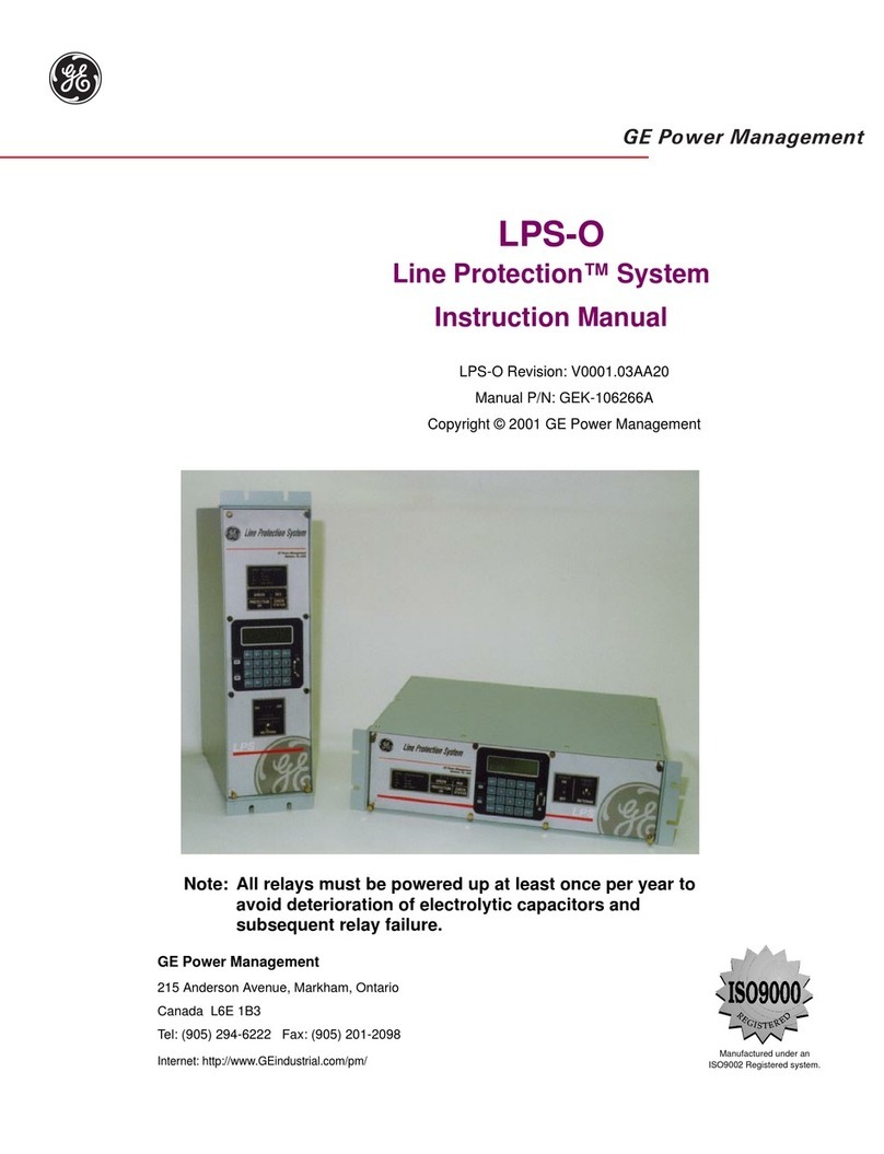
GE DIAC User manual

DIAC / DIFC / DSFC
DIGITAL OVERCURRENT PROTECTION
Instruction Manual
Manual P/N: GEK-105570C
Copyright © 2001 GE Power Management
GE Power Management
215 Anderson Avenue, Markham, Ontario
Canada L6E 1B3
Tel: (905) 294-6222 Fax: (905) 294-8512
Internet: http://www.GEindustrial.com/pm Manufactured under an
ISO9002 Registered system.
g
GE Power Management
Note: All relays must be powered up at least once per year to
avoid deterioration of electrolytic capacitors and subsequent
relay failure.


*(.&
DIAC / DIFC / DSFC Digital Overcurrent Protection 1
TABLE OF CONTENTS
INTRODUCTION........................................................................................................................ 3
PRODUCT DESCRIPTION ........................................................................................................ 4
GENERAL....................................................................................................................................................4
APPLICATION...............................................................................................................................................4
FUNCTIONS.................................................................................................................................................4
CALCULATION OF SETTINGS............................................................................................... 23
HARDWARE DESCRIPTION................................................................................................... 24
CASE........................................................................................................................................................24
ADJUSTMENTS ..........................................................................................................................................24
TARGETS AND INDICATORS........................................................................................................................24
RESET AND MANUAL TRIP .........................................................................................................................25
TRIP CIRCUIT TEST ...................................................................................................................................25
TRIP CIRCUIT............................................................................................................................................25
COVER INSTALLATION DIAC AND DSFC.....................................................................................................25
RECEIVING, HANDLING AND STORAGE .......................................................................................................25
INSTALLATION....................................................................................................................... 26
ENVIRONMENT ..........................................................................................................................................26
MOUNTING................................................................................................................................................26
SURGE GROUND (DIAC AND DSFC)..........................................................................................................26
SURGE GROUND AND RFI IMMUNITY (DIFC ONLY)......................................................................................26
ACCEPTANCE TESTS ............................................................................................................ 33
VISUAL INSPECTION...................................................................................................................................33
MECHANICAL INSPECTION..........................................................................................................................33
ELECTRICAL TESTS ...................................................................................................................................33
PERIODIC TESTS AND SERVICING ...................................................................................... 39
PERIODIC TESTS .......................................................................................................................................39
SERVICING................................................................................................................................................39
SPECIFICATIONS ................................................................................................................... 41
BURDENS..................................................................................................................................................41
RATINGS...................................................................................................................................................42
BURDENS..................................................................................................................................................42
CONTACT RATINGS ...................................................................................................................................42
ENVIRONMENTAL.......................................................................................................................................42
INSULATION WITHSTAND TESTS.................................................................................................................42
SURGE WITHSTAND CAPABILITY ................................................................................................................42
RADIO FREQUENCY WITHSTAND ................................................................................................................42
ELECTROSTATIC DISCHARGE .....................................................................................................................42
APPLICATION NOTES............................................................................................................ 43
IOC/TOC UNIT.........................................................................................................................................43
Cover Photo: 8919670

*(.&
2 DIAC / DIFC / DSFC Digital Overcurrent Protection
LIST OF FIGURES
FIGURE 0: FRONT VIEW DIFC (8919654)................................................................................................................... 3
FIGURE 1: IAC51 TOC CURVE.................................................................................................................................... 6
FIGURE 2: IAC53 TOC CURVES................................................................................................................................. 7
FIGURE 3: 55 SHORT TIME TOC CURVES ................................................................................................................ 8
FIGURE 4: 57 MEDIUM TIME TOC CURVES .............................................................................................................. 9
FIGURE 5: 66 LONG TIME TOC CURVES ................................................................................................................ 10
FIGURE 6: 75 SHORT TIME TOC CURVES .............................................................................................................. 11
FIGURE 7: IAC77 TOC CURVES............................................................................................................................... 12
FIGURE 8: 95 SHORT TIME TOC CURVES .............................................................................................................. 13
FIGURE 9: IEC INVERSE TOC CURVES................................................................................................................... 14
FIGURE 10: IEC VERY INVERSE TOC CURVES...................................................................................................... 15
FIGURE 11: IEC EXTREMELY INVERSE TOC CURVES.......................................................................................... 16
FIGURE 12: IEEE INVERSE TOC CURVES .............................................................................................................. 17
FIGURE 13: IEEE VERY INVERSE TOC CURVES.................................................................................................... 18
FIGURE 14: IEEE EXTREMELY INVERSE TOC CURVES........................................................................................ 19
FIGURE 15: DEFINITE TIME...................................................................................................................................... 20
FIGURE 16: I2T TIME CURVE .................................................................................................................................... 21
FIGURE 17: IOC CURVE............................................................................................................................................ 22
FIGURE 18: DIAC AND DSFC EXTERNAL / INTERNAL CONNECTIONS............................................................... 27
FIGURE 19: DIFC EXTERNAL / INTERNAL CONNECTIONS................................................................................... 28
FIGURE 20: DIAC PANEL MOUNTING AND DRILLING........................................................................................... 29
FIGURE 21: DIFC PANEL MOUNTING AND DRILLING........................................................................................... 30
FIGURE 22: SURFACE MOUNTING DIFC................................................................................................................. 31
FIGURE 23: DSFC PANEL MOUNTING AND DRILLING.......................................................................................... 32
FIGURE 25: DIAC OR DSFC TEST SETUP FOR PICKUP AND OPERATING TIME VERIFICATION..................... 37
FIGURE 26: DIFC TEST SETUP FOR INSTANTANEOUS UNIT...............................................................................37
FIGURE 27: DIAC OR DSFC TEST SETUP FOR INSTANTANEOUS....................................................................... 38
FIGURE 28 (9819647/8919648): DIAC FRONT AND REAR VIEWS......................................................................... 39
FIGURE 29 (8919652/8919653): DIFC FRONT AND REAR VIEWS ......................................................................... 40
FIGURE 30 (8919632/8919661): DSFC FRONT AND REAR VIEWS........................................................................ 40
FIGURE 31: BURDEN CURVE................................................................................................................................... 41
FIGURE 32: IOC/TOC UNIT ....................................................................................................................................... 43
These Instructions do not purport to cover all details or variations in equipment
nor provide for every possible contingency to be met in connection with the in-
stallation, operation, or maintenance. Should further information be desired or
should particular problems arise which are not covered sufficiently for the pur-
chaser’s purpose, the matter should be referred to the GENERAL ELECTRIC
COMPANY. To the extent required the product described herein meets applicable
ANSI, IEEE, NEMA, and IEC standards; but no assurances are given with respect to
local codes and ordinances because they vary greatly

*(.&
DIAC / DIFC / DSFC Digital Overcurrent Protection 3
INTRODUCTION
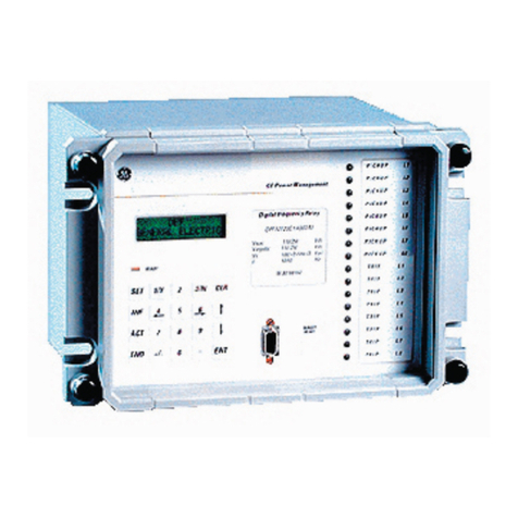
Figure 0: Front View DIFC (8919654)
FEATURES
•Digital single Phase overcurrent protection
•General-purpose feeder protection
•50 / 51 applications
•Self-powered
•16 Selectable curves
•Reset curve enable/disable
•Low Burden
•Fully Retrofitable *
•Functional separate TOC and IOC opera-
tions.
•Wide settings range.
•Drawout case construction
*When replacing unit and case (see instruction
manual INSTALLATION section for details).
51
52
50
Main Bus
To Load

*(.&
4 DIAC / DIFC / DSFC Digital Overcurrent Protection
PRODUCT DESCRIPTION
General
The DIAC, DIFC and DSFC are a family of self-
powered, single-phase, digital overcurrent relays.
The DIAC is packaged in a GE S1 style case, the
DIFC is packaged in a GE C1 style case and the
DSFC is packaged in a GE V1 style case. See the
HARDWARE DESCRIPTION section for mounting
dimensions.
The table below gives the model number break-
down.
D_ _CA _ _
B Revision
1 1 Amp Nominal Current
5 5 Amp Nominal Current
IF C1 case
IA S1 case
SF V1 case
These relays use waveform sampling of the current
input together with appropriate algorithms to pro-
vide a time overcurrent (TOC) and an instantane-
ous overcurrent (IOC) function.
Application
Time and instantaneous overcurrent functions are
widely used in many applications throughout the
power system. Typical examples are protection of
utility and industrial feeders and short circuit and
overload protection for transformers, and motors.
For feeder protection, the usual application re-
quires one relay per phase and a fourth relay con-
nected in the residual circuit of three ‘wye’ con-
nected current transformers (CTs). A typical exter-
nal connection diagram for this application is
shown in Figure 18 OR 19. Use of a separate
ground relay provides more sensitive protection for
ground faults.
The TOC reset characteristics can be set to emu-
late those of an induction disk or set for fast reset
with no intentional delay.
Functions
The TOC function operates on an ‘RMS’ current
calculated from the sampled values. The IOC func-
tion operates on the sampled values, and the algo-
rithm virtually eliminates the decaying DC offset
component to achieve low transient overreach of
less than 7%.
The relays contain two independent settings, one
for TOC and one for IOC.
TOC
The TOC function provides 16 selectable time cur-
rent curves.
•IAC51
•IAC53
•55-SHORT TIME
•57-MEDIUM TIME
•66-LONG TIME
•75-SHORT TIME
•IAC77
•95-SHORT TIME
•IEC Inverse
•IEC Very Inverse
•IEC Extremely Inverse
•IEEE Inverse
•IEEE Very Inverse
•IEEE Extremely Inverse
•Definite Time
•I2T
The IAC51, IAC53 and IAC77 curves match the
time current curve of the respective IAC model.
This includes the 0.5 through 9.9 time dial setting
and for both the 1 and 5 amp units. Numbered
curves 55, 57, 66, 75, and 95 match the shape of
the respective IAC model however the time dial
positions are not one to one equivalents. The IEC,
IEEE and I2t curves are based on the following
equations:
NOTE:
••••••••••••••••••••••••••••••••••
IEC equations are defined by IEC 255-4 and IEEE
equations are defined by IEEE PC37.112
••••••••••••••••••••••••••••••••••
In the following equations,
M = multiple of pickup
TD = time dial (0.5, 1, …, 9.9)
t = time (seconds)

*(.&
DIAC / DIFC / DSFC Digital Overcurrent Protection 5
IEC Inverse
See Figure 9 for graph of equation
TD
M
t
timePickup
TD
M
t
timeReset
−
=
−
−
=
−
1
014.0
1
97.
02.0
2
IEC Very Inverse
See Figure 10 for graph of equation
TD
M
t
timePickup
TD
M
t
−
=
−
−
=
−
1
35.1
1
32.4
1
2
timeReset
IEC Extremely Inverse
See Figure 11 for graph of equation
TD
M
t
timePickup
TD
M
t
timeReset
−
=
−
−
=
−
1
0.8
1
82.5
2
2
IEEE Inverse
See Figure 12 for graph of equation
TD
M
t
timePickup
TD
M
t
timeReset
+
−
=
−
−
=
−
0228.0
1
0103.
1
97.
02.0
2
IEEE Very Inverse
See Figure 13 for graph of equation
TD
M
t
timePickup
TD
M
t
timeReset
+
−
=
−
−
=
−
0982.0
1
922.3
1
32.4
2
2
IEEE Extremely Inverse
See Figure 14 for graph of equation
TD
M
t
timePickup
TD
M
t
timeReset
+
−
=
−
−
=
−
02434.0
1
64.5
1
82.5
2
2
I2T
See Figure 16 for graph of equation
TD
M
t
timePickup
TD
M
t
timeReset
=
−
=
−
2
2
250
2

*(.&
6 DIAC / DIFC / DSFC Digital Overcurrent Protection
0.1 2345567 1234556 10 234556 100
0.1
2
3
4
5
66
7
1
2
3
4
5
66
7
10
2
3
4
5
66
7
100
DIAC, DIFC, & DSFC
OVERCURRENT RELAYS
IAC 51
RESET OPERATE
.5
1
2
3
4
5
6
7
8
9
9.9
Time Dial Settings
Inverse Standard
Pow er M anagem ent
Frequency: 50/60 Hertz
0.1 - 3.18 (1 Ampere Relays)
General Electric CO., 205 Great Valley Parkway, Malvern, PA 19355
0358A1104
Multiples of Pickup Settin
g
Time in Seconds
Time Dial Ran
g
e: (0.5 - 9.9)
Current Ran
g
e: 0.5 - 15.9 ( 5 Ampere Relays)
GES10023
Figure 1: IAC51 TOC Curve

*(.&
DIAC / DIFC / DSFC Digital Overcurrent Protection 7
0.1 2345567 1234556 10 234556 100
0.01
2
3
44
5
6
0.1
2
3
44
5
6
1
2
3
44
5
6
10
2
3
44
5
6
100
2
DIAC, DIFC, & DSFC
OVERCURRENT RELAYS
IAC 53
RESET OPERATE
.5
1
2
3
4
5
6
78
9
Time Dial Settings
9.9
Very Inverse Standard
Pow er M anagem ent
Frequency: 50/60 Hertz
0.1 - 3.18 (1 Ampere Relays)
General Electric CO., 205 Great Valley Parkway, Malvern, PA 19355
0358A1105
Multiples of Pickup Setting
Time in Seconds
Time Dial Range: (0.5 - 9.9)
Current Range: 0.5 - 15.9 ( 5 Ampere Relays)
GES10024
Figure 2: IAC53 TOC Curves

*(.&
8 DIAC / DIFC / DSFC Digital Overcurrent Protection
0.1 2345567 1234556 10 234556 100
0.01
2
3
4
5
66
7
0.1
2
3
4
5
66
7
1
2
3
4
5
66
7
10
DIAC, DIFC, & DSFC
OVERCURRENT RELAYS
55 - ST
RESET OPERATE
.5
1
2
3
4
5
6
7
8
9
9.9
Time Dial Settings
Short Time
Pow er M anagem ent
Frequency: 50/60 Hertz
0.1 - 3.18 (1 Ampere Relays)
General Electric CO., 205 Great Valley Parkway, Malvern, PA 19355
0358A1106
Multiples of Pickup Setting
Time in Seconds
Time Dial Range: (0.5 - 9.9)
Current Range: 0.5 - 15.9 ( 5 Ampere Relays)
GES10025
Figure 3: 55 Short Time TOC Curves

*(.&
DIAC / DIFC / DSFC Digital Overcurrent Protection 9
0.1 2345567 1234556 10 234556 100
0.1
2
3
4
5
66
7
1
2
3
4
5
66
7
10
2
3
4
5
66
7
100
DIAC, DIFC, & DSFC
OVERCURRENT RELAYS
57 - MT
RESET OPERATE
Time Dial Settings
.5
1
2
3
4
5
6
7
8
9
9.9
Inverse Medium
Pow er M anagem ent
Frequency: 50/60 Hertz
0.1 - 3.18 (1 Ampere Relays)
General Electric CO., 205 Great Valley Parkway, Malvern, PA 19355
0358A1107
Multiples of Pickup Setting
Time in Seconds
Time Dial Range: (0.5 - 9.9)
Current Range: 0.5 - 15.9 ( 5 Ampere Relays)
GES10026
Figure 4: 57 Medium Time TOC Curves

*(.&
10 DIAC / DIFC / DSFC Digital Overcurrent Protection
0.1 2345567 1234556 10 234556 100
0.1
2
3
4
55
6
1
2
3
4
55
6
10
2
3
4
55
6
100
2
3
4
55
6
1000
DIAC, DIFC, & DSFC
OVERCURRENT RELAYS
66 - LT
RESET OPERATE
Inverse Long
.5
1
2
3
Time Dial Settings
4
5
6
78
99.9
Pow er M anagem ent
Frequency: 50/60 Hertz
0.1 - 3.18 (1 Ampere Relays)
General Electric CO., 205 Great Valley Parkway, Malvern, PA 19355
0358A1108
Multiples of Pickup Setting
Time in Seconds
Time Dial Range: (0.5 - 9.9)
Current Range: 0.5 - 15.9 ( 5 Ampere Relays)
GES10027
Figure 5: 66 Long Time TOC Curves

*(.&
DIAC / DIFC / DSFC Digital Overcurrent Protection 11
0.1 2345567 1234556 10 234556 100
0.01
2
3
4
55
6
0.1
2
3
4
55
6
1
2
3
4
55
6
10
2
3
4
55
6
100
DIAC, DIFC, & DSFC
OVERCURRENT RELAYS
75 - ST
RESET OPERATE
Inverse Medium Short
.5
1
2
3
Time Dial Settings
4
5
6
78
99.9
Pow er M anagem ent
Frequency: 50/60 Hertz
0.1 - 3.18 (1 Ampere Relays)
General Electric CO., 205 Great Valley Parkway, Malvern, PA 19355
0358A1109
Multiples of Pickup Setting
Time in Seconds
Time Dial Range: (0.5 - 9.9)
Current Range: 0.5 - 15.9 ( 5 Ampere Relays)
GES10028
Figure 6: 75 Short Time TOC Curves

*(.&
12 DIAC / DIFC / DSFC Digital Overcurrent Protection
0.1 2345567 1234556 10 234556 100
0.01
2
3
44
5
6
0.1
2
3
44
5
6
1
2
3
44
5
6
10
2
3
44
5
6
100
2
DIAC, DIFC, & DSFC
OVERCURRENT RELAYS
IAC 77
RESET OPERATE
Extremely Inverse Standard
.5
1
2
3
4
5
Time Dial Settings
6
7
9.9
98
Pow er M anagem ent
Frequency: 50/60 Hertz
0.1 - 3.18 (1 Ampere Relays)
General Electric CO., 205 Great Valley Parkway, Malvern, PA 19355
0358A1110
Multiples of Pickup Setting
Time in Seconds
Time Dial Range: (0.5 - 9.9)
Current Range: 0.5 - 15.9 ( 5 Ampere Relays)
GES10029
Figure 7: IAC77 TOC Curves

*(.&
DIAC / DIFC / DSFC Digital Overcurrent Protection 13
0.1 2345567 1234556 10 234556 100
0.01
2
3
4
55
6
0.1
2
3
4
55
6
1
2
3
4
55
6
10
2
3
4
55
6
100
DIAC, DIFC, & DSFC
OVERCURRENT RELAYS
95 - ST
RESET OPERATE
Inverse Short
.5
1
2
3
4
5
Time Dial Settings
6
78
99.9
Pow er M anagem ent
Frequency: 50/60 Hertz
0.1 - 3.18 (1 Ampere Relays)
General Electric CO., 205 Great Valley Parkway, Malvern, PA 19355
0358A1111
Multiples of Pickup Setting
Time in Seconds
Time Dial Range: (0.5 - 9.9)
Current Range: 0.5 - 15.9 ( 5 Ampere Relays)
GES10030
Figure 8: 95 Short Time TOC Curves

*(.&
14 DIAC / DIFC / DSFC Digital Overcurrent Protection
0.1 2345567 1234556 10 234556 100
0.01
2
3
4
55
6
0.1
2
3
4
55
6
1
2
3
4
55
6
10
2
3
4
55
6
100
DIAC, DIFC, & DSFC
OVERCURRENT RELAYS
IEC Inverse
RESET OPERATE
Time Dial Settings
3
2
1
.5
4
5
6
78
99.9
Pow er M anagem ent
Frequency: 50/60 Hertz
0.1 - 3.18 (1 Ampere Relays)
General Electric CO., 205 Great Valley Parkway, Malvern, PA 19355
0358A1112
Multiples of Pickup Setting
Time in Seconds
Time Dial Range: (0.5 - 9.9)
Current Range: 0.5 - 15.9 ( 5 Ampere Relays)
GES10031
Figure 9: IEC Inverse TOC Curves

*(.&
DIAC / DIFC / DSFC Digital Overcurrent Protection 15
0.1 2345567 1234556 10 234556 100
0.01
2
3
44
5
6
0.1
2
3
44
5
6
1
2
3
44
5
6
10
2
3
44
5
6
100
2
DIAC, DIFC, & DSFC
OVERCURRENT RELAYS
IEC VERY INVERSE
RESET OPERATE
.5
1
2
3
4
5
6
9.9
7
8
9
Time Dial Settings
Pow er M anagem ent
Frequency: 50/60 Hertz
0.1 - 3.18 (1 Ampere Relays)
General Electric CO., 205 Great Valley Parkway, Malvern, PA 19355
0358A1113
Multiples of Pickup Setting
Time in Seconds
Time Dial Range: (0.5 - 9.9)
Current Range: 0.5 - 15.9 ( 5 Ampere Relays)
GES10032
Figure 10: IEC Very Inverse TOC Curves

*(.&
16 DIAC / DIFC / DSFC Digital Overcurrent Protection
0.1 2345567 1234556 10 234556 100
0.01
2
3
44
5
6
0.1
2
3
44
5
6
1
2
3
44
5
6
10
2
3
44
5
6
100
2
DIAC, DIFC, & DSFC
OVERCURRENT RELAYS
IEC Ext. Inv.
RESET OPERATE
Extremely Inverse
.5
Time Dial Settings
9.9
98
7
6
5
4
3
2
1
Pow er M anagem ent
Frequency: 50/60 Hertz
0.1 - 3.18 (1 Ampere Relays)
General Electric CO., 205 Great Valley Parkway, Malvern, PA 19355
0358A1114
Multiples of Pickup Setting
Time in Seconds
Time Dial Range: (0.5 - 9.9)
Current Range: 0.5 - 15.9 ( 5 Ampere Relays)
GES10033
Figure 11: IEC Extremely Inverse TOC Curves

*(.&
DIAC / DIFC / DSFC Digital Overcurrent Protection 17
0.1 2345567 1234556 10 234556 100
0.01
2
3
4
55
6
0.1
2
3
4
55
6
1
2
3
4
55
6
10
2
3
4
55
6
100
DIAC, DIFC, & DSFC
OVERCURRENT RELAYS
IEEE Inverse
RESET OPERATE
Time Dial Settings
.5
1
2
3
4
5
6
78
99.9
Pow er M anagem ent
Frequency: 50/60 Hertz
0.1 - 3.18 (1 Ampere Relays)
General Electric CO., 205 Great Valley Parkway, Malvern, PA 19355
0358A1115
Multiples of Pickup Setting
Time in Seconds
Time Dial Range: (0.5 - 9.9)
Current Range: 0.5 - 15.9 ( 5 Ampere Relays)
GES10034
Figure 12: IEEE Inverse TOC Curves

*(.&
18 DIAC / DIFC / DSFC Digital Overcurrent Protection
0.1 2345567 1234556 10 234556 100
0.01
2
3
44
5
6
0.1
2
3
44
5
6
1
2
3
44
5
6
10
2
3
44
5
6
100
2
DIAC, DIFC, & DSFC
OVERCURRENT RELAYS
IEEE Very Inv.
RESET OPERATE
Time Dial Settings
.5
1
2
3
4
5
6
78
99.9
Very Inverse
Pow er M anagem ent
Frequency: 50/60 Hertz
0.1 - 3.18 (1 Ampere Relays)
General Electric CO., 205 Great Valley Parkway, Malvern, PA 19355
0358A1116
Multiples of Pickup Setting
Time in Seconds
Time Dial Range: (0.5 - 9.9)
Current Range: 0.5 - 15.9 ( 5 Ampere Relays)
GES10035
Figure 13: IEEE Very Inverse TOC Curves
Other manuals for DIAC
1
This manual suits for next models
2
Table of contents
Other GE Relay manuals