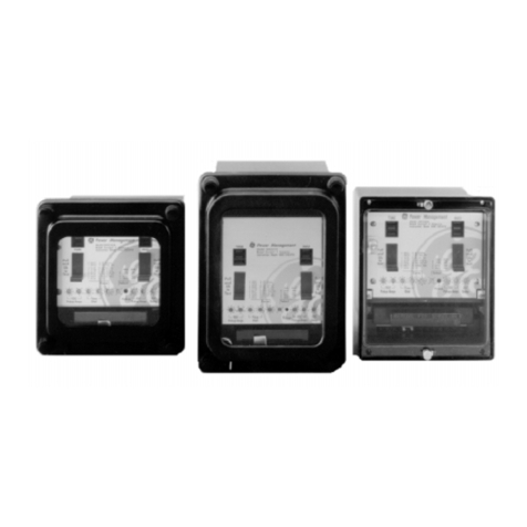
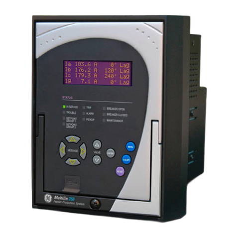
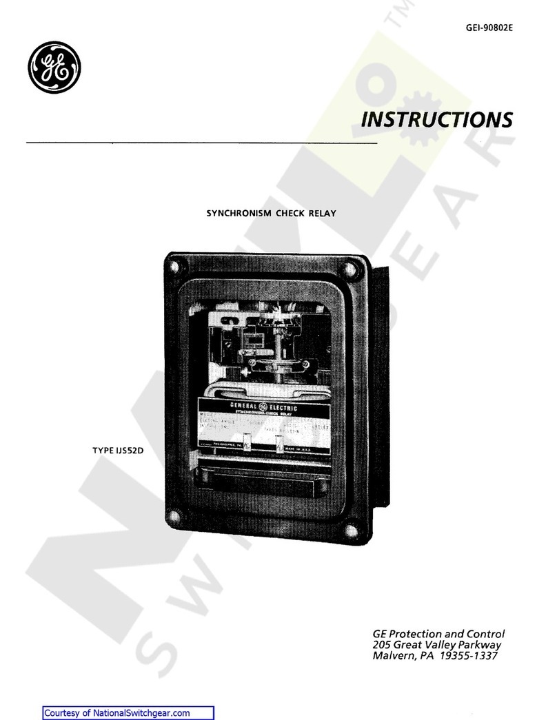
GE MOV 2000 User manual

ÿ
GE Power Management
MOV 2000
Instructions
InstructionsInstructions
Instructions
GEK 106271
GEK 106271GEK 106271
GEK 106271
Digital Multifunctional Protection,
Control and Supervision Relay

*(3RZHU0DQDJHPHQW
$Q\WKLQJ\RXFDQ·WILQG"
$Q\WKLQJQRWFOHDUHQRXJK"
,) <28 +$9( $1< &200(17 21 7+( &217(176 2) 7+(
35(6(17 0$18$/ .,1'/< )$; 86 $ &23< 2) 7+,6 3$*(
72*(7+(5 :,7+ $ &23< 2) 7+( 3$*( :+(5( <28 +$9(
)281' 7+( 352%/(0 72 7+( )$; 180%(5
),//,1*,17+(48(67,21$,5(%(/2::(:,//%(+$33<72
62/9( <285 '28%76 $1' :( 7+$1. <28 )25 +(/3,1* 86
,03529(7+,60$18$/
&RPSDQ\
1DPH
$GGUHVV
3KRQH
)D[
(PDLO
'HVFULSWLRQRI\RXUTXHVWLRQRUVXJJHVWLRQ
0DQXDO*(.FRGH


TABLE OF CONTENTS
GEK-106271 MIV Digital Multifunctional Protective Relay 1
TABLE OF CONTENTS
TABLE OF CONTENTSTABLE OF CONTENTS
TABLE OF CONTENTS
1. GENERAL DESCRIPTION AND APPLICATION....................................................................................5
1.1. GENERAL DESCRIPTION .................................................................................................................................5
2. OPERATION PRINCIPLES.....................................................................................................................7
2.1. PROTECTION FUNCTIONS ...............................................................................................................................7
2.1.1. A FUNCTION........................................................................................................................................7
2.1.2. FUNCTION - A’.....................................................................................................................................7
2.1.3. FUNCTION - B......................................................................................................................................8
2.1.4. FUNCTION - C......................................................................................................................................8
2.1.5. FUNCTION - D......................................................................................................................................8
2.1.6. FUNCTION - E......................................................................................................................................8
2.1.7. FUNCTION - F......................................................................................................................................8
2.1.8. FUNCTION - J.......................................................................................................................................9
2.1.9. FUNCTION - G......................................................................................................................................9
2.1.10. FUNCTION - H....................................................................................................................................9
2.1.11. FUNCTION - I .....................................................................................................................................9
2.1.12. Function 25 for the side 52 (521) ........................................................................................................9
2.1.13. FUNCTION 25 for Central 52 (520) ....................................................................................................9
2.2. MONITORING AND REGISTERING FUNCTIONS.................................................................................................10
2.2.1. Measuring............................................................................................................................................10
2.2.2. Status of the Associated Line Selector Switch....................................................................................10
2.2.3. Visual Signalling (LEDs)......................................................................................................................10
2.2.4. SELF TEST OF THE UNIT. ................................................................................................................11
2.3. ANALYSIS FUNCTIONS...........................................................................................................................11
2.3.1. EVENT RECORDER...........................................................................................................................11
2.3.2. OSCILLOGRAPHY RECORDING ......................................................................................................13
2.4. CONTROL ....................................................................................................................................................14
2.4.1. SETTINGS TABLES ...........................................................................................................................14
2.4.2. TIME SYNCHRONIZATION................................................................................................................14
2.4.3. CONFIGURABLE INPUTS AND OUTPUTS.......................................................................................15
2.4.3.1. Digital Inputs ................................................................................................................................................15
2.4.7.2. Outputs.........................................................................................................................................................15
2.5. HUMAN-MACHINE INTERFACE (HMI) ....................................................................................................15
2.6. REMOTE COMMUNICATIONS.................................................................................................................16
3. SETTINGS.............................................................................................................................................21
4. TECHNICAL CHARACTERISTICS.......................................................................................................31
4.1. MODEL LIST..................................................................................................................................................31
4.2. TECHNICAL CHARACTERISTICS ...........................................................................................................31
5. HARDWARE DESCRIPTION................................................................................................................35
5.1. PHYSICAL DESCRIPTION................................................................................................................................35
5.1.1. CASE...................................................................................................................................................35
5.1.2. ELECTRICAL CONNECTIONS ..........................................................................................................35
5.1.3. INTERNAL CONSTRUCTION ............................................................................................................35
5.2. OPERATION THEORY..............................................................................................................................36
5.2.1. MAGNETIC MODULE.........................................................................................................................36
5.2.2. CPU BOARD.......................................................................................................................................36
5.2.3. POWER SUPPLY ...............................................................................................................................37
5.2.4. KEYPAD AND DISPLAY.....................................................................................................................37
6. ACCEPTANCE TESTS..........................................................................................................................39
6.1. CONNECTIONS AND NECESSARY EQUIPMENT..................................................................................39
6.2. VISUAL INSPECTION...............................................................................................................................39
6.3. INSULATION TESTS.................................................................................................................................39

TABLE OF CONTENTS
2 MIV Digital Multifunctional Protective Relay GEK-106271
6.4. INDICATORS............................................................................................................................................40
6.5. POWER SUPPLY .....................................................................................................................................40
6.6. COMMUNICATIONS.................................................................................................................................41
6.7. MEASURES...............................................................................................................................................41
6.8. CHECKING THE INPUTS.........................................................................................................................41
6.9. CHECKING THE OUTPUTS.....................................................................................................................41
6.10. KEYPAD, DISPLAY AND LEDS..............................................................................................................43
6.11. FUNCTIONSA&A’(TIMEDOVERVOLTAGEUNITS).........................................................................43
6.12. FUNCTIONS B, C & D (VOLTAGE ABSENCE FUNCTIONS) ...............................................................45
6.13. FUNCTIONS E, F, & J (VOLTAGE PRESENCE UNITS).......................................................................48
6.14. FUNCTIONS G, H & I (WEAK INFEED UNITS).....................................................................................49
6.15. FUNCTIONS 25 (SIDE AND CENTRAL SYNCHRONISM)....................................................................50
6.16. IRIG-B .....................................................................................................................................................53
7. INSTALLATION AND MAINTENANCE................................................................................................ 55
7.1. INSTALLATION.........................................................................................................................................55
7.2. SAFETY GROUND CONNECTION AND SUPPRESSION OF DISTURBANCES...................................55
7.3. MAINTENANCE........................................................................................................................................55
8. KEYPAD AND DISPLAY ......................................................................................................................57
8.1. MENU TREE.............................................................................................................................................59
8.2. SETTINGS GROUP..................................................................................................................................60
8.3. INFORMATION GROUP........................................................................................................................... 64
8.4. OPERATIONS GROUP ............................................................................................................................65
8.5. SINGLE KEY OPERATION.......................................................................................................................66
8.6. CONFIGURATION MENU. .......................................................................................................................66
FIGURES ......................................................................................................................................................... 69

TABLE OF CONTENTS
GEK-106271 MIV Digital Multifunctional Protective Relay 3
LIST OF DRAWINGS
Figure 1. Panel mounting diagram (226B6086H10)............................................................. ........... ....70
Figure 2. Front view (226B7412H9)...................................................................................... ................71
Figure 3. External Connections (189C4129 H1)................................................................... ................72
Figure 4. RS232 connection (MOV with PC).................................................................... .... ................73
Figure 5. RS232 connection (MOV with MODEM)................................................................. ...............73
Figure 6. Rear view (226B7412H10)........................................................................ ........... .................74
Figure 7. Dimensions diagram (226B6086H10)................................................................... .................75
LIST OF TABLES
TABLE 1. Default LED configuration.................................................................... .................................11
TABLE 2. List of events.......................................................................................... ...............................11
TABLE 3. Internal protection status............................................................. .................................... .....17
TABLE 4. Settings common to all tables...................................................................................... .........22
TABLE 5. Independent settings for each table.............................................................................. ........23
TABLE 6. HMI menu. Description................................................................................................ .........59
TABLE 7. HMI menu. Settings & Ranges............................................................ ......................... ........60
TABLE 8. Settings change procedure............................................................................................ .......63
TABLE 9. Relay status information............................................................................................... ........64

TABLE OF CONTENTS
4 MIV Digital Multifunctional Protective Relay GEK-106271

1. GENERAL DESCRIPTION AND APPLICATION
GEK-106271 MIV Digital Multifunctional Protective Relay 5
1.
1.1.
1. GENERAL DESCRIPTION AND APPLICATION
GENERAL DESCRIPTION AND APPLICATIONGENERAL DESCRIPTION AND APPLICATION
GENERAL DESCRIPTION AND APPLICATION
1.1. GENERAL DESCRIPTION
The MOV system is a digital multifunction unit for protection, control, and measure, using a group or
algorithms that allow the implementation of different voltage functions, described on section 2 of the present
instruction manual.
The MOV system is housed in a 19’’ 2 units high rack. Figure 1 shows the panel drilling dimensions.
The information and functions management can be performed with a PC connected to the serial port
(RS232 or fibre optic), or using the man-machine interface (MMI), that includes a 20 key keypad and an LCD with
two rows of 16 characters each, on the front of the unit.
The functions included in this system are as follows:
a) Protection:
•Undervoltage functions (A, A’).
•Voltage absence functions (B, C, D).
•Voltage presence functions (E, F, J).
•Weak infeed functions (G, H, I).
•Closing and reclosing permission functions for two breakers.
b) Monitoring and Registering:
•Three-phase line voltage, busbars 1 &2 voltage measurement
•Associated line selector switch status.
•Optical signalling with 17 LED indicators (16 configurable).
•Self-check.
c) Analysis:
•Event recording.
•Oscillography recording.
d) Control:
•3 settings tables.
•Time synchronization using communications, or IRIG-B.
•Configurable inputs and outputs.
•User configurable internal logic.
e) Communications Interfaces:
•Local and remote communications using three connectors, one on the front and two on the rear of the unit.
•Manual interface (MMI) with keypad and alphanumeric display.
•GE-INTRO configuration software and GE-LOCAL communications software, Windowsäbased. Both
software packages are part of the GE-NESIS (GE NEtwork Substation Integration System).

1. GENERAL DESCRIPTION AND APPLICATION
6 MIV Digital Multifunctional Protective Relay GEK-106271

2. OPERATION PRINCIPLES
GEK-106271 MIV Digital Multifunctional Protective Relay 7
2.
2.2.
2. OPERATION PRINCIPLES
OPERATION PRINCIPLESOPERATION PRINCIPLES
OPERATION PRINCIPLES
2.1. PROTECTION FUNCTIONS
The MOV general connections diagram, and the external voltage commuting required is shown on the
following diagram:
2.1.1. A FUNCTION
=V1*(V2*89+(V3*V4*V5)*89)*TMP
where:V1 = Undervoltage on bus 1.
V2 = Undervoltage on bus 2 (or line 2)
V3 = Undervoltage on line phase A.
V4 = Undervoltage on line phase B.
V5 = Undervoltage on line phase C.
89 = Line Selector switch closed.
89 = Line Selector switch open.
* = logic AND.
+=logicOR.
TMP = time setting for function A.
This function consists on detecting undervoltage (1.1. setting) on both sides of the side breaker (in case of
breaker and a half schemes), during a certain period of time (setting 2.1.). It monitors the Busbar voltage (V1) and
the line voltage values (V3, V4, V5) or V2, depending on the status of the line disconnection switch. The operation
of this function allows the side breaker to trip and signal undervoltage to the control system.
2.1.2. FUNCTION - A’
=(V1*89+(V3*V4*V5)*89)*TMP’
This function detects undervoltage (setting 1.1.) on the line side associated to the central breaker. In order
to monitor undervoltage on both sides of the central breaker, this function needs to be ANDed with function A’ of
the MOV relay protecting the other two breakers (contacts in series).
89-2
89-1
89-1
89-2
V2
V1 V3, V4,
MO
MO
V3, V4,
V2
V1
Va, Vb,
Vb
Va, Vb,
Vb
L1
B1
L2
B2
521
520
89-2
89-1

2. OPERATION PRINCIPLES
8 MIV Digital Multifunctional Protective Relay GEK-106271
2.1.3. FUNCTION - B
=V3*V4*V5
This function detects voltage absence (setting 1.2.)on the line in order to allow a line grounding operation.
2.1.4. FUNCTION - C
=V1+(V2*89)+(V3*V4*V5)*89
This function detects the voltage absence (setting 1.2.) on any or both sides of the side breaker, in order
to allow the side breaker closing, when the remote connection cannot operate due to the lack of voltage. This
function can be used also for emergency closing.
2.1.5. FUNCTION - D
= (V1 * 89) + (V3 * V4 * V5) * 89
This function detects the voltage absence on the line side of the central breaker. Voltage absence on any
side of the central breaker can be detected by parallel connecting the operation of both MOVs protecting the
breaker. The use of this function is the same as function C, but for the central breaker.
2.1.6. FUNCTION - E
=V1*(V2*89+(V3+V4+V5)*89)
This function detects the voltage presence (setting 1.3.) on both sides of the side breaker.
2.1.7. FUNCTION - F
=(V1*89+(V3+V4+V5)*89)
This function detects voltage presence on both sides of the central breaker, by series connecting the
operations of both MOVs protecting the breaker and a half scheme. It is used for sending a signal to the control
system and the remote connection.

2. OPERATION PRINCIPLES
GEK-106271 MIV Digital Multifunctional Protective Relay 9
2.1.8. FUNCTION - J
=V1+V2*89+(V3+V4+V5)*89
This function detects voltage presence (setting 1.3.) in one or both sides of the side breaker. It can be
used for conditioning the undervoltage trip to voltage presence. This allows the breaker to close when there is no
voltage (voltage absence) avoiding an undervoltage trip afterwards.
2.1.9. FUNCTION - G
=V3
This function detects weak infeed condition (setting 1.4) on line phase A (V3).
2.1.10. FUNCTION - H
=V4
This function detects weak infeed condition (setting 1.4) on line phase B (V4).
2.1.11. FUNCTION - I
=V5
This function detects weak infeed condition (setting 1.4) on line phase C (V5).
2.1.12. FUNCTION 25 FOR THE SIDE 52 (521)
The MOV2 includes different settings for closing and reclosing permissions. It also includes different
masks for permissions in the case of DL-DB, LL-DB. DL-LB and/or Synchronism during a selectable period of time
(settings 3.4, and 3.5). In order to verify the synchronism between both sides of the side breaker, the unit checks
that the difference in module, phase, and frequency of voltage values V1, and V2 (when the line selector switch is
open), or V1, and V4 (when the line selector switch is closed) are smaller than settings 3.1, 3.2, and 3.3.
The synchronism check function only operates for LL-LB conditions, that is, when voltage on both sides of
the breaker is equal or higher than the voltage presence setting (setting 1.3). Once this condition is present,
voltage must fall below the voltage absence setting (setting 1.4) in order to become a Dead Line or Dead Bus
situation.
For this breaker, the BUS side refers to the voltage value independent from the line 89, that is, V1. The
LINE side refers to voltage values V4 or V2, depending on the status of 89.
2.1.13. FUNCTION 25 FOR CENTRAL 52 (520)
The MOV2 includes different settings for closing and reclosing permission. It also includes
different masks for permissions in the case of DL-DB, LL-DB. DL-LB and/or Synchronism during a selectable
period of time (settings 3.4, and 3.5). In order to verify the synchronism between both sides of the central breaker,
the unit checks that the difference in module, phase, and frequency of voltage values V1, and V2 (when the line
selector switch is open), or V1, and V4 (when the line selector switch is closed) are smaller than settings 4.1, 4.2,
and 4.3.
The synchronism check function only operates for LL-LB conditions, that is, when voltage on both sides of
the breaker is equal or higher than the voltage presence setting (setting 1.3). Once this condition is present,
voltage must fall below the voltage absence setting (setting 1.4) in order to become a Dead Line or Dead Bus
situation.

2. OPERATION PRINCIPLES
10 MIV Digital Multifunctional Protective Relay GEK-106271
For this breaker, the BUS side refers to the voltage value independent from the line 89, that is, V2. The
LINE side refers to voltage values V4 or V1, depending on the status of 89.
2.2. MONITORING AND REGISTERING FUNCTIONS.
2.2.1. MEASURING
The MOV system can measure the following magnitudes:
-Line voltage values (three phases), for busbar 1 and 2, in module, phase, and frequency.
These measures can be accessed locally on the unit’s LCD, or using the communications software GE-
LOCAL.
2.2.2. STATUS OF THE ASSOCIATED LINE SELECTOR SWITCH
The MOV system monitors the status of an associated line selector switch through digital inputs 89/a, and
89/b when the selector switch is set to have two contacts, and through input 89/a when it is set to have only one
contact. The selector switch status is accessible using the local MMI, or the communications program. This last
will display the status in real time on a bay mimic, visible in the GE-LOCAL program. (This screen, as well as the
measures screen, can be configured by the user with GE-INTRO configuration software).
2.2.3. VISUAL SIGNALLING (LEDS).
The status represents the digital information from all the equipment units (inputs, pickups, alarms, etc.).
Those signals included in the status are grouped in groups of 16; there are 10 different groups in the status; the
last group corresponds to the 16 AND gates that can be defined using the programmable logic through GE-INTRO
software. Therefore, the desired signals, or the result of an AND gate from a group can be taken to this last group
AND1....AND16.
The MOV unit front panel has a total of 17 LED indicators. One of them is a two-color LED with a fixed
function, system alarm (RED), or system ready (GREEN). The rest are red color LEDs, and can be configured by
the user with the GE-INTRO software; they can be assigned either to an event (selectable between the 32
protection and 16 communications events), or to an AND gate of up to 16 events. Events are defined using the
protection or communications status, assigning one of them to the activation of a status, or an OR gate of up to 16
status included in the same group.
Besides, each LED can be configured to incorporate a memory in case of lack of power supply (the status
of those LEDs with memory is stored in EEPROM memory, so that when the power supply is restored, those LEDs
that were lit before the power breakdown will continue to be lit), and to be blinking or not.
A LED testing option is included. All indicators will light up when pressing the TARGET RESET
pushbutton. This button allows to reset the LED signals when it is kept pressed.
MOV units are supplied with the following default LED configuration:

2. OPERATION PRINCIPLES
GEK-106271 MIV Digital Multifunctional Protective Relay 11
Table 1. Default LED configuration
COLUMN
LED Nº LEFT LED Nº RIGHT
1 Function A (with memory) 9 Function H
2 Function A’ (with memory) 10 Function I
3 Function B 11 Function J
4 Function C 12 521 Instantaneous synchronism
5 Function D 13 520 Instantaneous synchronism
6 Function E 14
7 Function F 15
8 Function G 16 Local communication mode (blinking)
2.2.4. SELF TEST OF THE UNIT.
The MOV system incorporates, thanks to its digital technology, self-test functions that guarantee its correct
operation, and will disable the unit in case of internal orders.
These self-tests are performed both during start-up and normal operation. Tests are carried out on the internal
power supply, program memory (ROM), working memory (RAM), oscillography memory (RAM) and the settings
and calibration memory (EEPROM).
Additionally, a hardware test is included for the signalling LEDs. All of them will light up when pressing the
TARGET RESET button. If this button is pressed for more than one second, the memorised indicators will be
deleted.
2.3. ANALYSIS FUNCTIONS
The MOV system includes event recording and oscillography with time resolution of 1 millisecond. In order
to maintain the integrity of date and time, as well as the oscillography record, there is a capacitor backup for the
internal high-resolution clock and the oscillography memory, with capacity for storing the information during at
least 24 hours after a power supply breakdown.
2.3.1. EVENT RECORDER
The MOV keeps a record of the last 165 events, including date and time (with 1 ms resolution), event type,
current and voltage values when the event occurred, and unit status information.
This record is stored in a non volatile memory and is maintained event without power supply.
The following table shows the possible causes for an event:
Table 2. Causes for events
Index Status
0.0 Program start-up
0.1 Settings change
0.2 Counters writing
0.5 W/o timers
0.6 Out of service

2. OPERATION PRINCIPLES
12 MIV Digital Multifunctional Protective Relay GEK-106271
Index Status
1.0 Parallel EEPROM alarm
1.1 Serial EEPROM alarm
1.4 Default general settings ALARM
1.5 Default Table 1 settings ALARM
1.6 Default Table 2 settings ALARM
1.7 Default Table 3 settings ALARM
2.0 EXTERNAL TRIGGER
2.1 ACTIVE TABLE-1
2.2 ACTIVETABLE-2
2.3 ACTIVETABLE-3
2.4 COMMUNICATIONS TRIGGER
4.0 UNDERVOLTAGE (mT-VaL1)
4.1 UNDERVOLTAGE (mT-VbL1)
4.2 UNDERVOLTAGE (mT-VcL1)
4.3 UNDERVOLTAGE (mT-V1)
4.7 UNDERVOLTAGE (mT-V2)
5.0 VOLTAGE ABSENCE (aT-VaL1)
5.1 VOLTAGE ABSENCE (aT-VbL1)
5.2 VOLTAGE ABSENCE (aT-VcL1)
5.3 VOLTAGE ABSENCE (aT-V1)
5.7 VOLTAGE ABSENCE (aT-V2)
6.0 VOLTAGE PRESENCE (pT-VaL1)
6.1 VOLTAGE PRESENCE (pT-VbL1)
6.2 VOLTAGE PRESENCE (pT-VcL1)
6.3 VOLTAGE PRESENCE (pT-V1)
6.7 VOLTAGE PRESENCE (pT-V2)
7.0 WEAK INFEED (ad-VaL1)
7.1 VOLTAGE PRESENCE (ad-VbL1)
7.2 WEAK INFEED (ad-VcL1)
8.0 89L1 Status
8.1 Undefined (error) 89L1
8.2 89L1Opening failure ALARM
8.3 89L1Closing failure ALARM
12.0 DL-DB
12.1 LL-DB
12.2 DL-LB
12.3 LL-LB
12.4
12.5 SYNCH-Reclose (TMP1)
12.6
12.7 SYNCH-Close (TMP2)
13.0 DL-DB
13.1 LL-DB
13.2 DL-LB
13.3 LL-LB
13.4
13.5 SYNCH-Reclose (TMP1)
13.6
13.7 SYNCH-Close (TMP2)
14.0 FUNCTION-A (TMP)
14.1 FUNCTION-A' (TMP)
14.2 FUNCTION-B
14.3 FUNCTION-C
14.4 FUNCTION-D

2. OPERATION PRINCIPLES
GEK-106271 MIV Digital Multifunctional Protective Relay 13
Index Status
14.5 FUNCTION-E
14.6 FUNCTION-F
14.7 FUNCTION-G
15.0 FUNCTION-H
15.1 FUNCTION-I
15.2 FUNCTION-J
15.3 PERMISSION 79 521
15.4 CLOSING PERMISSION 521
15.5 PERMISSION 79 520
15.6 CLOSING PERMISSION 520
2.3.2. OSCILLOGRAPHY RECORDING
The MOV can store up to 4 oscillography records, with a resolution of 16 samples per cycle. Each record has a
maximum capacity of 62 cycles, and the number of pre-fault cycles is selectable between 1 and 8. Each record
includes the following information:
•Instantaneous values of voltage and current inputs (V3=VA,V
4
=VB,V
5
=VC, V1,V
2
):
•Digital information:
- Protection units status.
- Digital inputs status.
•Date and time.
•Causes that triggered the oscillography.
EXTERNAL TRIGGER
COMMUNICATION TRIGGER
FUNCTION-A (TMP)
FUNCTION-A' (TMP)
FUNCTION-B
FUNCTION-C
FUNCTION-D
FUNCTION-E
FUNCTION-F
FUNCTION-G
FUNCTION-H
FUNCTION-I
FUNCTION-J
•Active settings table in the moment of the record.
There is a configurable mask that determines which functions or internal status will trigger the oscillography. This
can be done either by a configurable digital inputs, by communications or from the HMI.
Oscillography records are retrieved and converted to COMTRADE (Standard IEEE C37.111-1991) format file,
using the GE-LOCAL communications software, and they can be viewed using the GE-OSC software, or any other
software package accepting COMTRADE or ASCII format (e.g. EXCELTM).

2. OPERATION PRINCIPLES
14 MIV Digital Multifunctional Protective Relay GEK-106271
2.4. CONTROL
2.4.1. SETTINGS TABLES
The MOV incorporates three independent settings tables, stored in a non volatile memory, so that they are
maintained event without power supply. Only one table is active at each time, and it is the one used by the system
to operate.
MOV settings are divided in generic groups (General settings, Switchgear settings, Oscillography masks and
Function Permissions). These are common to all setting tables. Other settings are separate for each table.
There is a setting called “ACTIVE TABLE” that allows choosing the settings table that will be active each time.
There is a way to switch the settings table using up to 2 digital inputs, named “TABLE SELECTION 0” and “TABLE
SELECTION 1”. These allow up to 4 combinations, from 0 to 3. For applications requiring a lower number of
tables (up to 2), we can use only one digital input.
The selected combination is obtain from the binary codification of the above referred inputs (please refer to the
following table). 0 means selecting the table shown on the “ACTIVE TABLE” setting. Numbers 1 to 3 select tables
1 to 3 (we must keep in mind that table 3 is always associated with cold load pickup, and has maximum priority.
Please refer to section 2.4.5.).
Number Table Selection 1 Table Selection 2 Active Table
0 0 0 Selected by setting
10 1 1
21 0 2
31 1 3
NOTE: If the active table is controlled using these inputs, this selection will have priority over the “ACTIVE TABLE”
setting, and the table used will be determined by the status of the digital inputs.
2.4.2. TIME SYNCHRONIZATION
The MOV system includes an input for time synchronization. This input requires the connection of a device
to supply a demodulated IRIG-B output. In this way co-ordinated universal time is measured to a high degree of
precision and this makes it possible to tag the events generated by the unit with a resolution of one millisecond.
The use of this input makes it possible to correlate data obtained from different units thanks to
synchronization with GPS satellites. In this way it is possible to obtain very useful information for analysis, cross-
referencing the information provided by different units for a given incident.
Alternatively, it is possible to synchronise units by means of communications, using the GE-LOCAL
communications software, or manually by means of the MMI. If the IRIG-B input is used it has priority over time
setting by communications, since the time read by IRIG-B is much more accurate.

2. OPERATION PRINCIPLES
GEK-106271 MIV Digital Multifunctional Protective Relay 15
2.4.3. CONFIGURABLE INPUTS AND OUTPUTS
2.4.3.1. Digital Inputs
The MOV system has 6 digital inputs (two groups of 3 inputs with one common in each group). The inputs
can be configured by the user by means of the GE-INTRO configuration program.
The inputs are configured using GE-INTRO configuration software. One of the following meanings can be
assigned to any input: (For more detail about the configuration of the inputs, see GE-INTRO Instruction Book).
•Table Selection 0 (L)
•Table Selection 1 (L)
•External trigger (P)
•89/a (L)
•89/b (L)
(L) Indicates a level input.
(P) Indicates a pulse input
There is also the IRIG-B synchronization input already mentioned.
The diagram of external connections, in figure 3, shows the default input configuration.
2.4.7.2. Outputs
The MOV system has 22 configurable outputs.
The outputs are configured using the GE-INTRO configuration software.
The technical characteristics of the outputs are shown in section 4.
The configurable outputs can be programmed using logic based on the internal protection states (pick-ups, trips,
alarms, etc.) The MOV has 160 different internal states, and these can be used to carry out logical operations
NOT, AND and OR, which gives to the unit a great flexibility.
The output configuration logic is done by using different levels. At the first level it is possible to use AND gates of
up to 16 signals (see section 2.2.3). The output is incorporated into the states matrix so that it can in turn be used
in next AND gates of up to 16 inputs. This process can continue until the 16 Ands are used.
Once the AND gates have been configured it is possible to create a second level with OR gates of 16 inputs
limited to the established groups of bytes, and whose logical outputs are assigned to physical outputs of the unit.
The default output configuration is included in the diagram of external connections in figure 3.
2.5. HUMAN-MACHINE INTERFACE (HMI)
The MOV system includes as standard a 20 key keyboard and a 2 line liquid crystal display (LCD) with 16
characters per line. This display has highly reliable LED diode back lighting (the screen brightness can be
adjusted on the rear of the front board).
By means of this interface the user can change the settings, view measurements, carry out operations and
access information stored in the unit. The functions of this local interface and how to use it are described in the
section KEYBOARD AND DISPLAY.

2. OPERATION PRINCIPLES
16 MIV Digital Multifunctional Protective Relay GEK-106271
2.6. REMOTE COMMUNICATIONS
The relay has 2 serial gates and three connectors. Gate 1 can be reached from the front of the relay in connector
1 (PORT 1 connector) or from the back (PORT 2 connector). The second gate can be reached from connector 3
(PORT 3 connector) which is located on the rear.
There are different models each with a different physical connection for the PORT 3 connector (RS-232 or fibre-
optic). In the "RS232" models the three connectors are RS232. In the "RS232 and fibre-optic" models the PORT1
and PORT2 connectors are RS232 while the PORT3 connector is replaced by a fibre-optic connector.
The PORT 1 connector has priority over the PORT 2 connector and is selected when the DCD (Data Carrier
Detect) signal is activated. Figure 8 shows how to make the connections to a personal computer.
Gate 1 (PORT 1 and PORT 2 connectors) and 2 (PORT 3 connector) are independent and the unit can
serve them simultaneously.
The communications protocol is the same as that used for the rest of the GE digital protection systems and
requires the use of the GE-LOCAL software. The instruction book for this program, which facilitates dialogue with
the relay, is supplied with the unit. The protocol is reliable and allows communication with different protection
systems. It guarantees very efficient data transfer (especially for the oscillography and other large files) along with
error detection and automatic communication recovery.
The status of the local/remote communication is indicated on the front of the unit by LED indicator 16 (the
last LED in the right-hand column.) Local communication refers to communication via the keyboard/display (local
display showing any information except for the initial MOV GENERAL ELECTRIC screen), or via communications
gate 1 (PORT 1, PORT2 connectors), and remote communication refers to connection via gate 2 (PORT 3 rear
connector).
Local and remote communications can exist at the same time, although there is only one possibility for
changing settings and carrying out operations, since this can only be done with the communication which has
priority (local communication) while the other is limited only to accessing information. When the local
communication is interrupted, either by the disconnection of PORT 1 connector or because the HMI is on the initial
screen (a situation which can be caused intentionally, or automatically if no key has been pressed for 15 minutes),
the remote communication recovers the ability to modify settings and carry out operations.

2. OPERATION PRINCIPLES
GEK-106271 MIV Digital Multifunctional Protective Relay 17
TABLE 3. Internal Protection Status
Index Status
0.0 Program start-up
0.1 Settings Change
0.2 Counters writing
0.3
0.4
0.5 WITHOUT TIME
0.6 OUT OF SERVICE
0.7
1.0 Parallel EEPROM ALARM
1.1 Serial EEPROM ALARM
1.2
1.3
1.4 Default General Settings ALARM
1.5 Default Table 1 Settings ALARM
1.6 Default Table 2 Settings ALARM
1.7 Default Table 3 Settings ALARM
2.0 EXTERNAL TRIGGER
2.1 ACTIVETABLE–1
2.2 ACTIVETABLE–2
2.3 ACTIVETABLE–3
2.4 COMMUNICATIONS TRIGGER
2.5
2.6
2.7
3.0 PI1
3.1 PI2
3.2 PI3
3.3 PI4
3.4 PI5
3.5 PI6
3.6
3.7
4.0 UNDERVOLTAGE (mT-VaL1)
4.1 UNDERVOLTAGE (mT-VbL1)
4.2 UNDERVOLTAGE (mT-VcL1)
4.3 UNDERVOLTAGE (mT-V1)
4.4
4.5
4.6
4.7 UNDERVOLTAGE (mT-V2)
5.0 VOLTAGE ABSENCE (aT-VaL1)
5.1 VOLTAGE ABSENCE (aT-VbL1)
5.2 VOLTAGE ABSENCE (aT-VcL1)
5.3 VOLTAGE ABSENCE (aT-V1)
5.4
5.5
5.6
5.7 VOLTAGE ABSENCE (aT-V2)
6.0 VOLTAGE PRESENCE (pT-VaL1)
Table of contents
Other GE Relay manuals
Popular Relay manuals by other brands

Siemens
Siemens Argus 8 7SG11 manual

Ei Electronics
Ei Electronics RadioLINK Relay Module Ei428 instruction manual

red lion
red lion Watchdog 6HBWDOG1 user manual

HANYOUNG NUX
HANYOUNG NUX HSR-2 Series instruction manual

Kieback&Peter
Kieback&Peter Z45FK Product description

HANYOUNG NUX
HANYOUNG NUX HSR-3SL series instruction manual