GE Match User manual

Match
Uninterruptible Power Supply
2200 - 3000 VA
Manufactured by:
GEDigitalEnergy
General Electric Company Telephone +41 (0)91 / 850 51 51
CH – 6595 Riazzino (Locarno) Fax +41 (0)91 / 850 51 44
Switzerland Website www.gedigitalenergy.com
GE Digital Energy
Technology for the Digital World. ver 2.0 - GB
Match UPS
g

LX: OPM_MAE_XXX_2K2_3K0_XGB_V020 1GE DE Match 2200-3000: user manual 2.0 (GB)
GE Digital Energy
g
USER MANUAL
Match
Uninterruptible Power Supply
Uninterruptible Power SupplyUninterruptible Power Supply
Uninterruptible Power Supply
2200 - 3000 VA
2200 - 3000 VA2200 - 3000 VA
2200 - 3000 VA
Please read these instructions carefully before installation and start-up of the Match UPS.
Keep this manual in a safe place for future reference.
CONTENTS
1 INTRODUCTION............................................................................................................2
1.1 Introduction
1.2 Safety Rules
1.3 Transport / Storage
2 INSTALLATION..............................................................................................................2
2.1 Installation Rules
2.2 Installation Procedure
3 OPERATION...................................................................................................................4
3.1 Start-up
3.1.1 Start-up, mains available
3.1.2 Start-up, mains not available
3.2 Use: Normal Operation
3.2.1 Normal operating conditions
3.2.2 Load indication
3.2.3 Auto-off (no-load shutdown)
3.2.4 Battery test
3.2.5 Switching off
3.3 Use: Status and Alarm Indications
3.3.1 Charger on
3.3.2 Normal operation
3.3.3 AVR active
3.3.4 On battery
3.3.5 Battery low
3.3.6 Replace battery
3.3.7 Overload
3.3.8 High temperature
3.3.9 Programmed shutdown
4 COMMUNICATION ........................................................................................................7
4.1 RS232 Port
4.2 Relay Interface Card (option)
4.3 SNMP Interface Card (option)
5 OPTIONAL FEATURES.................................................................................................8
5.1 Extended Runtime
5.2 PowerFLAG SerVICe Box for Modem Connection
6 MAINTENANCE..............................................................................................................7
6.1 General
6.2 Batteries
6.3 UPS Configuration Tool
7 TROUBLESHOOTING...................................................................................................9
8 SPECIFICATIONS........................................................................................................10
© General Electric Digital Energy. All rights reserved; reproduction without permission prohibited. This manual may be subject to
change; no liability can be accepted for any error or omission.
GB

LX: OPM_MAE_XXX_2K2_3K0_XGB_V020 2GE DE Match 2200-3000: user manual 2.0 (GB)
GE Digital Energy
g
1.1 Introduction
The GE (General Electric) Digital Energy Match UPS, an uninterruptible power supply, protects your
equipment from all forms of power interference, including complete power failures.
1.2 Safety Rules
!CAUTION: RISK OF ELECTRICAL SHOCK. After installation, the UPS system (UPS +
battery pack) contains batteries. The appliance outlets may be electrically live, even when
the UPS is disconnected from the mains.
!The UPS contains potentially hazardous voltages. Do not open the UPS, there are no user
serviceable parts inside.
!All maintenance and service work, including replacement of the batteries, should be
performed by qualified service personnel.
1.3 Transport / Storage
!No liability can be accepted for any transport damage when the equipment is shipped in non-
original packaging.
!Store the UPS in a dry location with the batteries in a fully charged state. Storage temperature
must be within -20 +45 "C. If the unit is stored for a period exceeding 3 months, optimal battery
lifetime is obtained if the storage temperature does not exceed 25°C.
!If the unit is stored for an extended period of time, the batteries must be recharged periodically.
Connect the battery pack to the UPS. Subsequently connect the unit to a wall outlet and recharge
the batteries for 24 hours:
- if the storage temperature is within -20 and +30°C: every 3 months,
- if the storage temperature is within -20 and +45°C: every month.
The shipment contains a Match UPS, a battery pack, one mains power cord, two IEC male-female output
cords, a data cable, a CD ROM and this manual. After unpacking, inspect the UPS for damage. If any
damage is present please immediately notify the carrier and place of purchase.
IMPORTANT:
Before making any connection and switching on the UPS, please check the following conditions:
!your mains supply is 220 - 240 Volts and 50 or 60 Hz, and
!the total power demand of the connected equipment does not exceed the rated output power of
the UPS (indicated on the rating label) (7, fig. 1).
2.1 Installation Rules
!The UPS is intended to be used in normal domestic and office situations.
!Protect the UPS, according to the wiring rules, with a 16A D-type fuse.
!The UPS must be powered from a single phase grounded wall outlet. Do not use extension
cords.
!Avoid locations that are excessively humid, near water, near heat sources or in direct sunlight.
!The ambient temperature should not exceed 40"C. Optimal battery lifetime is obtained if the
ambient temperature does not exceed 30"C.
!If you stack the UPS and its battery pack, always place the UPS on top.
!It is important that ventilation air can move freely around and through the unit. Do not block the air
vents.
!Do not plug appliances such as electric heaters, toasters and vacuum cleaners into the UPS.
!Be careful when connecting laser printers: be sure that the demanded power does not exceed the
capacity of the UPS.
!The sum of the leakage currents of the UPS and the connected loads should not exceed 3.5mA.
1 - Introduction
2 - Installation

LX: OPM_MAE_XXX_2K2_3K0_XGB_V020 3GE DE Match 2200-3000: user manual 2.0 (GB)
GE Digital Energy
g
2.2 Installation Procedure
1. Loosen the two screws and remove the pull relief
(2a, fig. 1). Connect the DC connector of the battery
pack (8, fig. 1) to the DC socket (2, fig. 1) of the
UPS. Re-install the pull relief with the two screws.
Using the DC socket of the battery pack (9, fig. 1)
you can install a second, third, etc. pack. See fig. 2
and section 5.1.
2. Using the output cord(s) provided, connect the
computer(s) to the appliance outlet(s) (1, fig. 1) of
the UPS. Spread the loads over the appliance
outlets as equally as possible. If you use a
distribution box to connect more than one appliance
per outlet, please note that the maximum AC-current
rating of each appliance outlet is 10Amps (outlets 1)
or 16Amps (outlet 1a). An output cord to connect a
load to outlet 1a is not shipped with the unit. See fig.
3.
3. Connect the mains power cord to the mains input
socket (5, fig. 1) of the UPS. See fig. 4.
4. Connect the mains power cord to a working,
grounded AC wall socket outlet. See fig. 4.
The green LED 'on' (10, fig. 6) will blink, and after 30
seconds illuminate continuously: the unit has
switched on, output power is available.
5. For best results, allow the UPS to recharge the batteries during a period of approx. 2 hours. It is
acceptable to use the UPS without first charging the battery, but the runtime may be reduced.
6. For advanced communication possibilities, the RS232 interface port (6, fig. 1) can be connected
to a computer system and/or optional interface cards (3, fig. 1) can be added. See chapter 4.
fig. 2
fig. 3
fig. 4
12a23
6
1a
7
5
282a
8
9
4
fig. 1

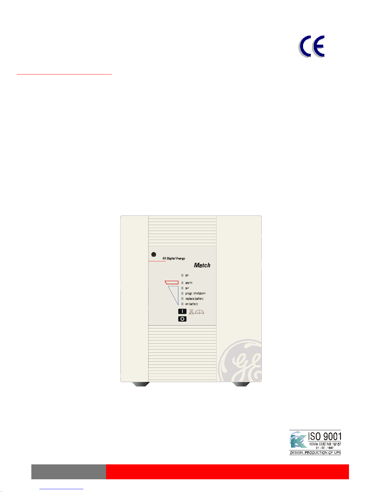
LX: OPM_MAE_XXX_2K2_3K0_XGB_V020 4GE DE Match 2200-3000: user manual 2.0 (GB)
GE Digital Energy
g
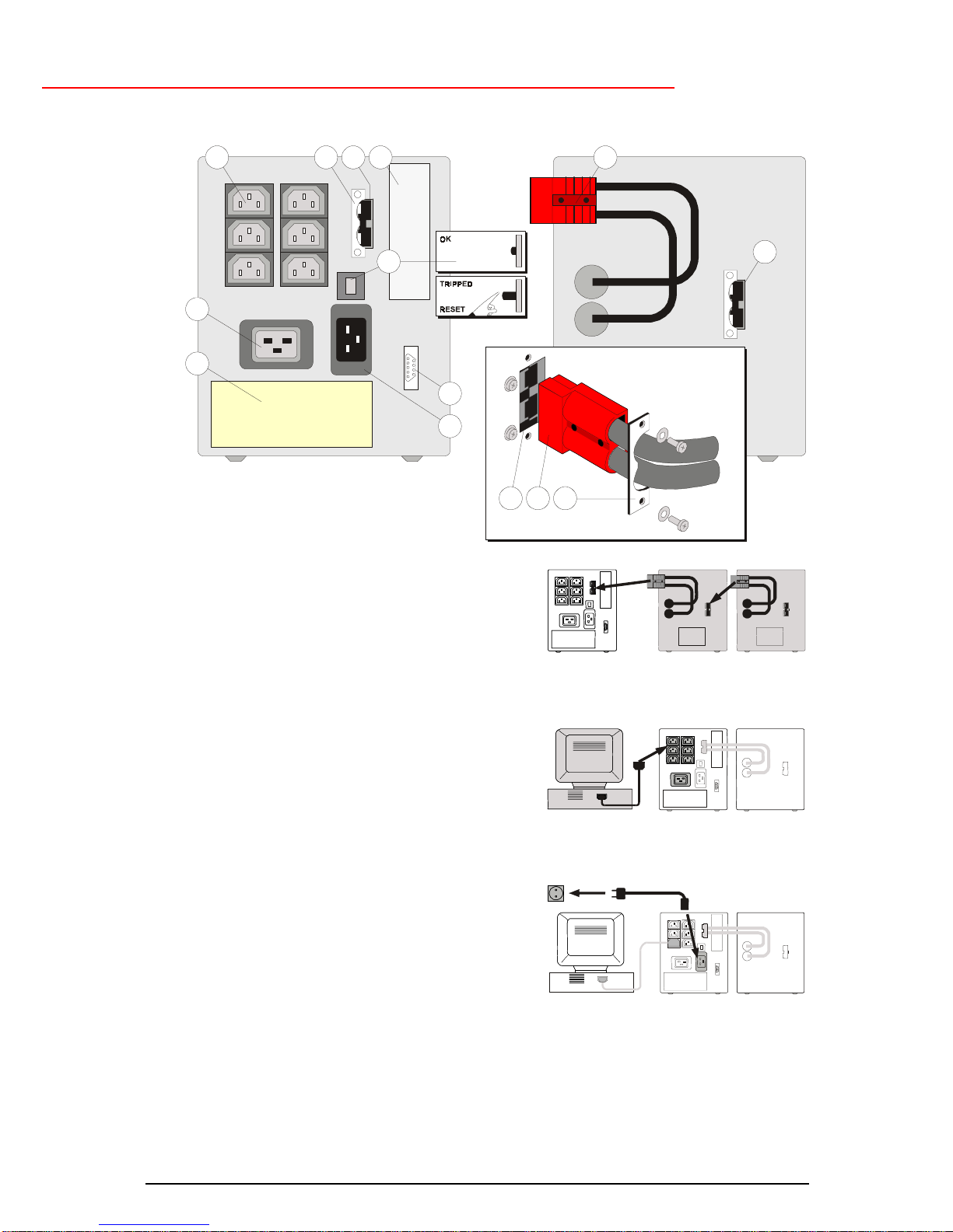
Please refer to figure 6.
3.1 Start-up
3.1.1 Start-up, mains available
After first installation the unit will start up automatically, see 2.2 step 4.
After switch-off via the front panel (3.2.5) the unit can be restarted as follows:
1. Press keypad 'I' (16, fig. 6) briefly; LED ‘on’ (already blinking) will illuminate continuously now.
2. The equipment connected to the UPS can now be switched on.
3.1.2 Start-up, mains not available
If the mains input is absent (power cord not connected, or mains failure):
1. Press keypad 'I' briefly, and then
2. Press keypad 'I' during 5 seconds until the buzzer sounds.
The LEDs 'on' and 'on battery' (15, fig. 6) will illuminate. The UPS operates on battery: it
discharges the batteries.
3.2 Use: Normal Operation
3.2.1 Normal operation conditions:
!the mains supply is present,
!the UPS is on,
!the load does not exceed the capacity of the UPS and
!the operating temperature is below alarm level.
3.2.2 Load indication (fig. 5)
1 During normal operation, press keypad 'I' briefly.
2 Yellow LEDs will blink during 3 seconds, the number is load
dependent (in case of overload LED 'alarm' (11, fig. 6) blinks as
well).
3.2.3 Auto-off (no-load shutdown)
If this function is activated, the UPS will switch off during a mains failure when the load is less
than 5% of the maximum load. In this way unnecessary discharging of the batteries is avoided.
The unit will automatically turn on again when mains power is restored. The default setting of the
no-load shutdown function is: activated. You can change this setting through the RS232 port,
using the UPS configuration tool that came with the unit (CD ROM, see 6.3). Please note that if
the UPS is not connected to the mains, and the battery pack is disconnected from the UPS, the
unit will return to the default setting.
3.2.4 Battery test (see also 3.3.6)
Manual battery test
1. During normal operation, press keypad 'I' and release it immediately after the second beep.
2. The duration of the test is 4 seconds, during which LED ‘on’ blinks.
Automatic battery test
The UPS conducts periodic automatic battery tests:
!5 hours after manual switch-on
!30 days from the last battery test, provided that the UPS remains switched on
Deep battery test
A deep battery test, to be initiated through the UPS software via the RS232 port, checks the
actual battery capacity in order to ensure accurate runtime prediction. During a deep battery test
the batteries will be discharged until 'battery low' alarm level. Please note that immediately after a
deep battery test the expected runtime is very short: allow the UPS to recharge its batteries. For
details please refer to the manual of your UPS software.
3.2.5 Switching off
1. Press keypad ‘0’ (17, fig. 6) approx. 1 second, until a beep is heard. LED ‘on’ will start blinking,
indicating that the battery charger remains active.
2. If electric isolation is required, unplug the power cord from the wall outlet.
fig. 5
3 - Operation

LX: OPM_MAE_XXX_2K2_3K0_XGB_V020 5GE DE Match 2200-3000: user manual 2.0 (GB)
GE Digital Energy
g
3.3 Use: Status and Alarm Indications
o= status indications : the operating mode
!= low priority alarms : abnormal operating situations
!! = high priority alarms : situations in which the actual output voltage of the UPS is no longer
guaranteed; immediate action should be taken
Indicators on front panel
Situation on alarm avr progr.
shutd. repl.
batt. on
batt. buzzer
o Charger on (3.3.1) - - - -
o Normal operation (3.3.2) ##
####
##
o Automatic voltage
regulation (3.3.3) ##
####
## - - - -
! On battery (3.3.4) ##
####
## ##
####
## - - - -*
1x/8 s.
!! Battery low (3.3.5) ##
####
## - - - - ##
####
## - - - -*
1x/s.
! Replace battery (3.3.6) ##
####
## ##
####
##
!! Overload (3.3.7) ##
####
## - - - - ##
####
##
!! High temperature (3.3.8) ##
####
## - - - - - - - -*
1x/s.
o Progr. shutdown
pending (3.3.9) ##
####
## - - - -
o Progr. shutdown in
progress (3.3.9) - - - - ##
####
##
Operating modes and corresponding indications, see 3.3.1. – 3.3.9.
- - - - = intermitting
##
####
## = continuous
* = resetable: press push button ‘I’ > 2 secs.
fig. 6
7
8
9
10 11 12 13 14

LX: OPM_MAE_XXX_2K2_3K0_XGB_V020 6GE DE Match 2200-3000: user manual 2.0 (GB)
GE Digital Energy
g
3.3.1 Charger on
The batteries are charging, see 3.2.5.
3.3.2 Normal operation
See 3.2.1.
3.3.3 AVR (Automatic Voltage Regulation) active
The quality of the incoming mains is poor, and the AVR boosts a low incoming voltage or reduces
a high one (see chapter 8).
3.3.4 On battery
The UPS uses the energy stored in the batteries: see chapter 8 ‘Batteries - runtime’.
The UPS will shutdown
!after the batteries have been discharged (automatic restart), or
!if keypad 'O' is pressed (restart via front panel required) or
!if a 'UPS shutdown' command is given by the computer (restart via front panel required).
!if the load is < 5% and the auto-off function is activated (see 3.2.3)
Runtime indication (fig. 7)
During battery operation, press keypad 'I' briefly. The 4 yellow
LEDs indicate during 3 seconds the remaining runtime for the
actual load.
3.3.5 Battery low (end of runtime)
The batteries are nearly discharged. Controlled shutdown of your
computer equipment should be completed within 1 minute.
3.3.6 Replace battery
The batteries are bad. The alarm only stops after the next battery test: if the batteries have been
either sufficiently charged (in case of discharged batteries) or replaced by a new set (in case of
worn out batteries).
3.3.7 Overload
The demanded power of the equipment exceeds the UPS's rated output power. If an overload
persists during battery operation, the UPS may shut down.
3.3.8 High temperature
Overtemperature shut down during battery operation can occur from:
!extreme environmental temperature,
!lack of proper ventilation,
!overload situation.
When the pre-alarm sounds, check these conditions to avoid shutdown or damage. If the
temperature rises further, the UPS will
!if it runs on mains: switch off the battery charger
!if it runs on battery: switch off completely. Output voltage is no longer available!
3.3.9 Programmed shutdown
The UPS monitoring software allows you to program a 'sleep period' of the UPS by sending two
commands to the UPS:
!shut down after # minutes (blinking LED), and subsequently:
!shut down during # hours (continuous LED).
The programmed shutdown (either pending or in progress) can be cancelled:
- press keypad 'I' for at least 5 seconds to cancel shutdown and switch UPS on.
- press keypad '0' for at least 5 seconds to cancel shutdown and switch UPS off.
fig. 7

LX: OPM_MAE_XXX_2K2_3K0_XGB_V020 7GE DE Match 2200-3000: user manual 2.0 (GB)
GE Digital Energy
g
4.1 RS232 Port (fig. 8)
The RS232 is a plug-in interface port (9-pin, Sub-D, male) which enables advanced communication
between the UPS and the computer (interface kit required).
We strongly recommend to use only original GE Digital Energy software products in combination with
the RS232 interface port.
Pin # Function
1 RS232 input (UPS shutdown)
2 RS232 output
3 No function
4 Plug and Play
5 Common
6 No function
7 No function
8 UPS connected
9 No function
4.2 Relay Interface Card (option)
The card is equipped with potential free change-over contacts for the following alarms:
!general alarm
!mains failure
!battery low
For more information please refer to the user manual that comes with the interface card.
4.3 SNMP Interface Card (option)
This card allows the data interface to be connected directly to an Ethernet network. When this card is
installed the RS232 communication link is no longer available.
For more information please refer to the user manual that comes with the interface card.
RS232
DC
RS232
Port
DC
RS232
DC
RS232
1
2
8
4
5
fig. 8
4 - Communication

LX: OPM_MAE_XXX_2K2_3K0_XGB_V020 8GE DE Match 2200-3000: user manual 2.0 (GB)
GE Digital Energy
g
Apart from the options described in 4.2 and 4.3 the following options are possible:
5.1 Extended Runtime
Extended runtime can be obtained by connecting more than one battery pack to the UPS (see 2.2.1). In
this case, to allow a reliable recalculation of the available runtime, the UPS must be informed about the
new total battery capacity. You can reprogram the battery capacity through the RS232 port, using the UPS
configuration tool that came with the unit (CD ROM, see 6.3). Simultaneously the recharge current will be
increased. Please note that if the UPS is not connected to the mains, and the battery pack is
disconnected from the UPS, the unit will return to the default settings.
Dependent of the charge condition of the new batteries the new runtime calculations may temporarily be
unreliable.
For extended runtime at 25°C ambient temperature no derating is required. For extended runtime at 35°C,
maximum load must be derated to 1.85kVA (Match 2200) and 2.5kVA (Match 3000).
5.2 PowerFLAG SerVICe Box for Modem Connection
If you connect the PowerFLAG SerVICe Box between the communication port of the UPS and a modem,
a programmed number can be dialed in case of a UPS alarm. It also allows service personnel to dial in
and check the status of the UPS to perform remote diagnostics. This way service costs, specially in
remote areas, can be reduced considerably.
6.1 General
The GE Digital Energy Match UPS is virtually maintenance free: take care of proper environmental
conditions and keep air inlets-outlets free of dust.
Please read 2.1.
6.2 Batteries
The service life of the battery is up to 6 years, depending on operating conditions.
As a healthy battery is critical to the performance of the UPS, an automatic battery test is performed
regularly to ensure failsafe operation. Moreover, keypad 'I' allows a manually started battery test.
See 3.2.4.
When the condition of the battery is critical, a 'replace battery' alarm will be activated. Have your dealer
replace the batteries as soon as possible. See 3.3.6.
6.3 UPS Configuration Tool
With the UPS configuration software, that came with the unit on CD ROM, you are able to change the
setting of the 'auto-off' function (3.2.3) and reprogram the battery capacity (5.1).
Insert the CD ROM in your computer, and
1. Select RUN from the start menu
2. Type a:\conftool (type for 'a' the appropriate drive letter)
3. Press ENTER
See also a:\README.TXT.
5 - Optional Features
6 - Maintenance

LX: OPM_MAE_XXX_2K2_3K0_XGB_V020 9GE DE Match 2200-3000: user manual 2.0 (GB)
GE Digital Energy
g
Whenever a malfunction occurs, first check external factors (e.g connections, temperature, humidity or
load) to determine whether the problem is caused by the unit itself or by its environment. Subsequently
check the thermal circuit breaker: it may be tripped. If so: reset it (see 4, fig.1) and be sure that the UPS is
not overloaded.
The following chart is a simple troubleshooting checklist only; if the suggested solution does not succeed,
or if the information is insufficient to solve the problem, please contact your dealer or consult
www.gedigitalenergy.com.
PROBLEM POSSIBLE CAUSE SOLUTION
Connected equipment not
operating properly, buzzer sounds
continuously
Overload causes reduced output
voltage Reduce load
UPS overload Reduce load, reset TCB
(4, fig. 1)
Thermal Circuit Breaker (TCB)
tripped
System failure Please contact your dealer or
consult www.gedigitalenergy.com
UPS will not switch on to normal
operation, LED 'on' remains off
(charger off)
Line cord not connected Read 2.2 'Installation'
Connect line cord
Dead socket-outlet, or mains
voltage < approx. 187Vac, or mains
frequency out of tolerance
Contact qualified electrician.
Battery start is possible: see 3.1.2
UPS overtemperature Read 2.1
Allow UPS to cool down
TCB tripped See above
UPS will not switch on to normal
operation, LED 'on' blinks Mains voltage between 140-
187Vac Contact qualified electrician
Batteries depleted Allow the UPS to recharge the
batteries
Battery pack not connected Read 2.2 ‘Installation’
Connect battery pack
UPS will not switch to battery
operation
System failure Please contact your dealer or
consult www. gedigitalenergy.com
Shut down by external (software)
command during mains failure Wait until mains returns
UPS overtemperature Read 2.1
Allow UPS to cool down
Mains failure, battery discharged Wait until mains returns
Programmed shutdown in progress See 3.3.9
UPS switched off automatically
The load is < 5% of the max. load
and no mains power is present.
(No-load shutdown function is
active, see 3.2.3)
Wait until mains returns
LED ‘replace battery’ illuminates,
buzzer is silent Battery Test just after installation or
mains failure Allow the UPS to recharge the
batteries
Battery Test shows weak battery Read 6.2, have the batteries
replaced
7 - Troubleshooting

LX: OPM_MAE_XXX_2K2_3K0_XGB_V020 10 GE DE Match 2200-3000: user manual 2.0 (GB)
GE Digital Energy
g
Match model : 2200 3000
Ratings at std. runtime
Voltage Amperes (VA), : 2200 3000
with computer type load
Watts (W) : 1540 2100
with resistive load
For ratings with extended runtime see 5.1
Input
AC input voltage : 220 - 240 V
AC input voltage window : 140 - 305 V, mains operation (if Iin < 16A)
Maximum AC input voltage : 350V (above 305V battery operation)
Minimum start-up AC voltage : 187 V (at any load)
Input frequency : 50 Hz or 60 Hz
Input frequency range : nominal ± 5 Hz
No-load power consumption,
normal operation : typically 15W
Max. AC input current (A) : 12 16
AC input TCB (A) : 16 16
Output
AC output voltage : 230 V (suitable for 220 - 240 V loads)
AC output voltage tolerance : nominal ± 2% (battery operation, RMS value)
Output frequency : 50Hz or 60Hz (autosensing)
Output frequency in case
of battery start : last detected frequency (off factory 50 Hz)
Output frequency stability : < ± 0.1Hz (battery operation)
Output waveform : sine wave
Power factor : 0.7
Transfer time : typical 4 ms.
Buck/Boost voltage regulation : at 140-305 V input voltage: output voltage 190-254V
Batteries (ratings given for 25°C)
Nominal voltage (Vdc) : 36 48
Number x capacity (Ah) of batteries : 6x7 8x7
Type : 12V, sealed lead acid, maintenance free
Service life : up to 6 years (depending on use)
Recharge current : 3.5 - 10A, depending on programmed battery capacity
Battery recharge time for 90%
capacity (hours, approximation) : 2 2
Runtime in minutes
at typical load (75%) : 7 7
Watts
60 210 263
180 82 104
300 50 69
420 35 47
600 22 30
900 11 17
1540 5 7
2100 - 5
General
Weight of UPS (kg) : 18.0 20.1
Weight of battery pack (kg) : 21.3 26.5
Dimensions (hxwxd, mm)
UPS and battery pack : 225 x 185 x 485
Enclosure / protection : steel - plastic / IP20
Environment
Safety : EN 50091-1-1
Electromagnetic compatibility : EN 50091-2
Ambient temperature at std. runtime : -10 to +40°C;
Sound at 1 meter : < 35 dB(A)
Maximum relative humidity : 95% (non-condensing)
8 - Specifications
Other manuals for Match
1
This manual suits for next models
2
Table of contents
Other GE UPS manuals

GE
GE Match User manual

GE
GE SG Series 400 User manual

GE
GE TLE 160 User manual

GE
GE Digital Energy VH 700 User manual

GE
GE Digital Energy LP 33 Series User manual

GE
GE SG SERIES 10 User manual

GE
GE Uninterruptible Power Supply User manual

GE
GE Power Supply User manual

GE
GE Amersham Imager 600 User manual

GE
GE EP 700T User manual

GE
GE On-line VH Series User manual

GE
GE SG 300 User manual

GE
GE Lanpro 33 User manual

GE
GE Digital Energy LP 11U Instruction Manual

GE
GE 8 Series User manual

GE
GE FGC TLE Series User manual

GE
GE Digital Energy SG Series User manual

GE
GE VH Series 700 User manual

GE
GE SG Series User manual

GE
GE NetPro Series User manual