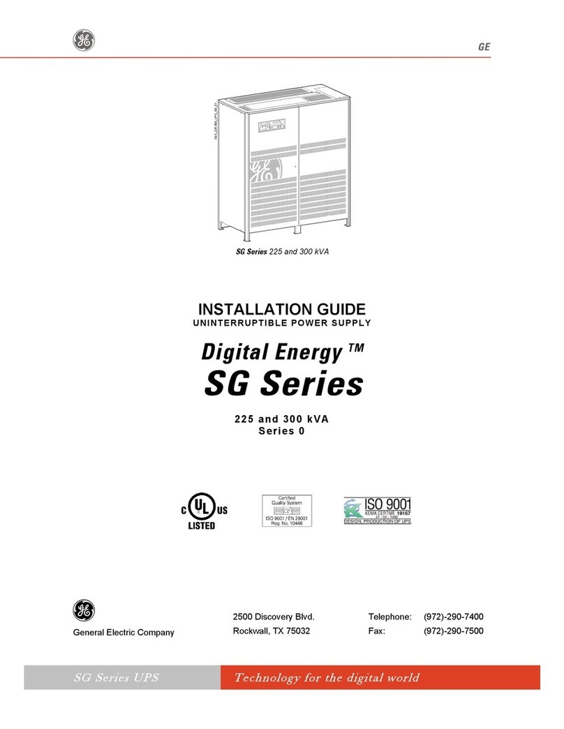
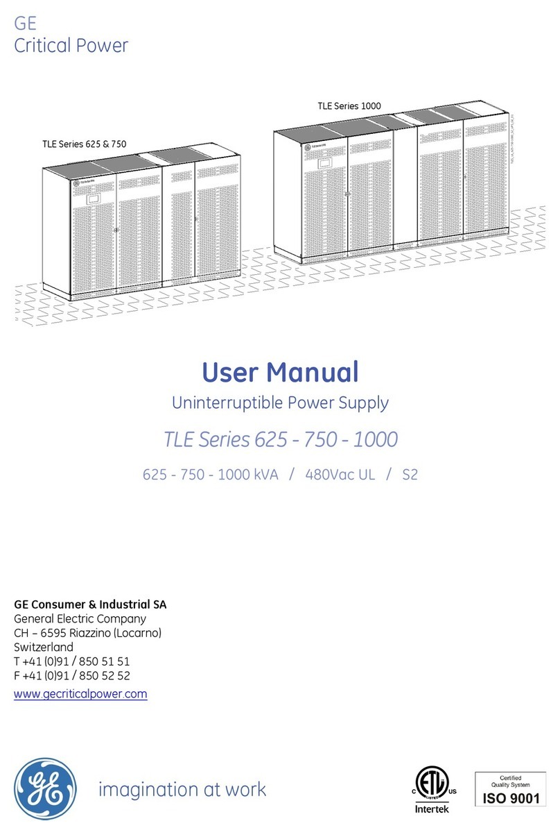
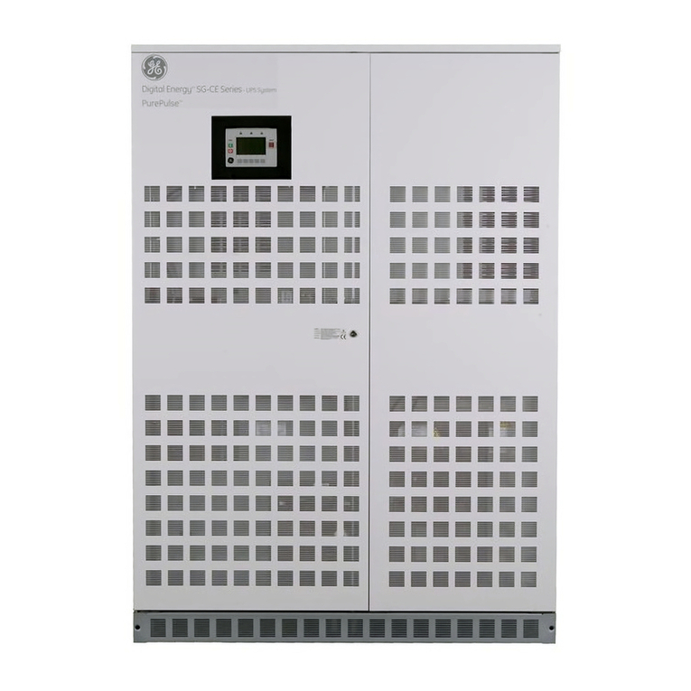
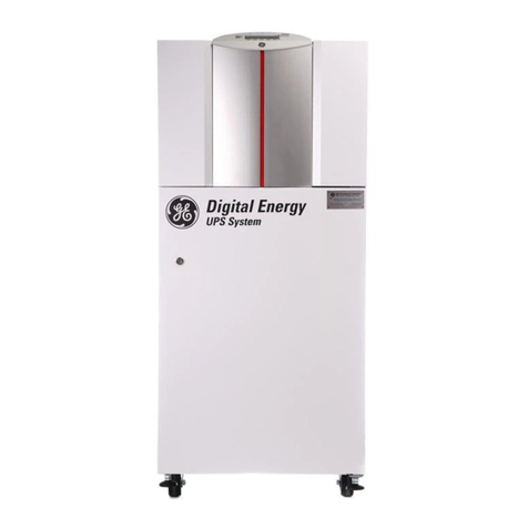
GE FGC TLE Series User manual

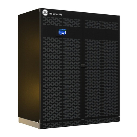
TLE SERIES UPS
40-150 KVA/KW, 480 VAC Three phase
Highly Ecient and Scalable
GE Industrial Solutions

2LP33 Series II UPS | www.gecriticalpower.com
TLE UPS Systems - Overview
Introduction
The TLE Series UPS is a robust, high performance 480/277VAC UPS
System suitable for a broad range of mission-critical applications
including data centers, data closets, healthcare/medical,
telecommunications, transportation, commercial buildings, and
industrial critical processes.
Design and Performance
The TLE Series UPS uses double conversion technology via a true on-line
VFI (voltage frequency independent) design. The IGBT Rectier provides
low input current harmonic distortion and a high input power factor to
minimize input feeder sizing. The IGBT Inverter with transformerless
output ensures low output voltage distortion and fast transient response
to high crest factor loads or step loads.
Multi-Mode Eciency
The TLE Series UPS can operate up to 98.9% eciency when
utilized in EcoMode operation. EcoMode continuously monitors the
output voltage and frequency, and will instantaneously switch to
double conversion mode and inverter usage during voltage and/or
frequency disturbances to insure compliance with the ITI (CBEMA)
curves for operation on sensitive IT server or other critical loads.
Redundant Parallel Architecture (“RPA”)
Redundant Parallel Architecture can be used on TLE Series UPS for up
to six (6) modules, for redundancy or capacity means. The RPA system
design eliminates single points of failure by using redundant controls and
an integrated bypass static switch in each UPS module. The RPA system
allows for exibility in output paralleling cabinet design and usage,
including load growth scaleability/expansion capabilities.
Site Services & Remote Monitoring
GE Critical Power Services oers a wide array of site services,
including product startup, preventative maintenance and emergency
maintenance. GE’s iUPSguard software allows for remote monitoring
of key subsystems within the UPS module and battery, allowing for
proactive dispatching and problem resolution when emergency repairs
are required.
Illustration picture

3LP33 Series II UPS | www.gecriticalpower.com
TLE UPS Systems - Overview (Cont.)
Features and Benets
• Transformerless design at
277/480VAC to reduce footprint and
weight, yet increase reliability.
• High input power factor and use
of a IGBT Rectifier eliminates the
use of oversized input feeders,
and maximizes standby generator
compatibility
• High switching frequency IGBT
Inverter provides best-in-class
transient response and low output
voltage distortion. An output
voltage waveform that closely
resembles utility power!
• Compact footprint and low audible
design, allows for use in most
commercial and industrial buildings
• Reliable paralleling of UPS modules via
GE’s RPA design, which eliminates any
and all common mode failure points
• Wide band of acceptable AC input
voltage and frequency, that eliminates
nuisance transfers to the battery
plant, thus maximizing battery jar life
• Internal battery management &
monitoring system (SBM) that
enhances battery life and reduces
cost of operation. Also eliminates
need for costly 3rd party bolt-on
battery monitoring systems
• Optional maintenance bypass
capabilities, via external
wrap-around cabinetry
• Optional 208VAC output, via matching
stepdown transformer cabinetry
• Optional output distribution
cabinet with panelboard or
subfeed circuit breakers
• Seismic area capabilities, via
seismic restraint hardware
and seismic lab testing
• Two Year Parts and Labor Warranty
TLE Series Ease of Installation & Improved Serviceability
Front Access
TLE Series is designed to have front access for all the critical components that reduces mean time to repair (MTTR).
Scalability & Slide Out Construction
The TLE Series UPS scales vertically to up to 150kW, and all sub-assemblies are designed to easily slide out
for fast maintenance and service. Now you can replace fans, caps, etc. as needed without having to replace
the entire power block.
Improved Diagnostic
TLE Series new diagnostic features allows to store dierent wave forms and also provides fan failure detection as
well as warning on capacitor life that improves UPS availability and enhances preventive maintenance capabilities.
Standard Safety and Maintenance Feature
To provide enhanced safety and protection the TLE Series UPS has standard built in back-feed protection.

4LP33 Series II UPS | www.gecriticalpower.com
TLE UPS System - Display & Control Panel Features
Measures
• Battery
• Rectifier
• Bypass
• Inverter
• Load
• Booster
Events
• Active alarms
• User Log
• Service Log
Setup
• Indentification
• User
• Printer
• Display
• eBoost/IEMi
• Touch Screen
• Identification
Commands
• Command 1
• Command 2
RPA
• RPA Parallel System
Advanced User Interface
The TLE Series UPS is equipped with menu-driven touch screen display panel provides easy to read details on
UPS status and metering, parameter settings, UPS conguration. This user-friendly display panel provides:
• Critical measurement of input, output and battery included
with mimic diagram
• Quick operational status
• Measurement and operational status of RPA system
• Different access level for user and service
• Multilanguage communication interface supporting: English, German, Italian, Spanish, French, Finnish, Polish, Portuguese,
Czech, Slovakian, Chinese, Swedish, Russian and Dutch.

5LP33 Series II UPS | www.gecriticalpower.com
1
200 10
0.8
0.7
0.9
4030 50 7060 80 90 100%
0.6
0.8
0.7
0.9
100% 90 80 70 60 50 40 30 20 10
ACTIVE POWER (kW)
LEADING POWER FACTOR
CAPACITIVE POWER (kVAr) Available power INDUCTIVE POWER (kVAr)
LAGGING POWER FACTOR
Input Performance
Clean Input Performance
The TLE Series IGBT based rectier and innovative control
algorithm ensures an input Total Harmonic Distortion (THDi)
of less than 3% and draws a pure sinusoidal waveform from
the mains. This also provides UPS input power factor of 0.99.
Advantages
• Saving in the sizing of upfront equipment e.g. emergency
generators, cablings, and circuit breakers
• No disturbances to nearby equipment; eliminate perturbation
and outage on upfront electrical equipment, avoiding also any
investigation and analysis cost due to malfunction
Programmable Soft Start
The programmable soft start allows the rectierto ramp up in a
programmable time period thus eliminating in-rush current.
This feature reduces the need of oversizing the input power
system (gensets, feeder cables, and overcurrent devices).
Generator Compatibility
User-programmable features such as slew rate, phase angle
rate-of-change and voltage rate-of-change allow the UPS
to quickly sync to a genset during emergency back-up.
Output Performance
Total Harmonic Distortion (THD)
A distorted output voltage waveform aects the proper
function of the load’s equipment. The TLE Series has
very low output voltage THD, even with connected
100% unbalanced or 100% non-linear loads.
Unity Output Power Factor
• TLE Series with unity output power factor provides more
real power. kVA equals KW – no derating with any load,
see Power Capability diagram below.
• Suitable for modern power supply application with unit or
capacitive power factor (e.g. new servers generation), crest
factor up to 3:1.
Transient Response
Transient response is very fast due to control algorithms
which ensure very high dynamic stiness. This reduces the
need to oversize the UPS for pulse load applications.
Unity output power factor, full power for critical load
without derating for actual and future IT loads.
TLE Series Power Capability

6LP33 Series II UPS | www.gecriticalpower.com
Redundant Parallel Architecture (RPA) System Congurations
GE provides RPA, a unique technology that can parallel UPS modules with true redundancy by eliminating any single point
of failure. RPA provides a scalable paralleling technique that reduces operating footprint and increases system reliability
by eliminating the need for external paralleling equipment and cabinets (centralized bypass and master control).
One of the UPS modules in the system intelligently takes the leadership role, while the other UPS modules have
access to all control parameters. If one UPS fails to operate, the load is automatically redistributed among the
others. If the lead UPS fails to operate, then another UPS automatically takes on the leadership role. GE’s RPA
technology is implemented by distributing the control electronics within each UPS module in the system.
RPA System Advantages
No Single Points of Failure
The RPA system provides complete redundancy of
all critical components, allows paralleling of up to 6
units for increased load capacity or redundancy.
Scalable
The system can be easily expanded for higher capacity
and redundancy without any interruption to the critical
load or transfer to bypass.
Distributed Control Logic
Each module in an RPA system has its own operational
controller. Each one continuously communicates with all
others in order to manage the entire system like a team.
Redundant Communication
Redundant high speed bus and control electronics
provide higher system reliability.
Online Maintenance
N+1 congurations allow maintenance on any single
module in the system while other modules provide
online protection with battery backup.
Sequential Soft Start
Provides sequential soft start of each module to reduce
instantaneous load on input feeders during mains recovery.
This helps avoid over-rating of generator and overheating
of cable and fuses.
Smaller Footprint
RPA eliminates the centralized control and external static
bypass cabinet.
RPA Conguration
Congurable up to 6 units
in parallel
• Future expansion
• Safe and reliable power supply
• Redundant Communication Bus
• Easy to install and maintain
• Easy system upgrade/downgrade
• Maintenance operation
without load interruption
True Redundancy with Distributed Control & Bypass
Standard RPA™ Conguration:

7LP33 Series II UPS | www.gecriticalpower.com
Powering Your Next... is our focus
GE’s TLE Series UPS is one of the most energy ecient double-conversion UPS in the industry, and provides world-class energy
eciency across the operating load range. The TLE Series delivers eciency up to 95.9% in double conversion mode.
GE’s UPS performance is optimized at 50-75% load operation, as this is the most common
operating range. The optimization of the TLE Series includes selecting all major power chain
components based on maximizing the component eciency at part load conditions.
TLE Series UPS Provides:
• Substantial reduction in operating cost of UPS
• Reduced energy loss minimizes air conditioning
requirement
• Energy savings from reduced cooling
80
83
86
89
92
95
98
25% 50%
Typical
Operating Load
TLE VFI Mode
75% 100%
Efficiency %
Load
UPS Block Diagram

8LP33 Series II UPS | www.gecriticalpower.com
TLE Series Power Capability
GENERAL DATA TLE 40 UL S1 TLE 50 UL S1 TLE 80 UL S1 TLE 100 UL S1 TLE 120 UL S1 TLE 150 UL S1
Topology VFI, double conversion
Nominal output power 40kW 50kW 80kW 100kW 120kW 150kW
Overall eciency in VFI mode Up to 95.9%
Overall eciency in SEM mode
(Super Eco Mode)
up to 98.9%
Audible noise level 62 dB(A)
Operating temperature range UPS: 32°F to 104°F/ 0°C to 40°C (122°F /50°C subjected to conditions)
Protection degree IP 30 (IEC 60529 - ANSI/NEMA 60529)
Standards UL 1778, UL marking
EMC (Electromagnetic Compatibility) EN/IEC 62040-2
Electrostatic discharge immunity 4kV contact / 8kV air discharge
Color RAL 9005 (Black)
Service access Front and top access only
External cable connections Bottom at the front of the cabinet or top with lateral sidecar
Paralleling (RPA version) Up to 6 units for redundancy or capacity in RPA conguration (option)
INVERTER
Nominal output voltage
(on site programmable)
3 x 480V + N
Output frequency 60 Hz
Output voltage tolerance: static +/- 1%
Output voltage tolerance: dynamic
(at load step 0 – 100 – 0%)
+/- 3%
– output voltage THD for 100%
linear load
<3%
– output voltage THD for 100%
non-linear load (EN 62040)
<5%
Output frequency tolerance:
free-running
+/- 0.1%
Overload capability
(at 25°C ambient temperature)
105% continuous, 110% - 10 minutes, 125% - 1 minute, 150% - 30 seconds
RECTIFER
Standard input voltage Nominal: 3 x 480V + N
Rectier accepted ph-ph
voltage range
410V - 550V (wider voltage range subject to de-rated loads)
Input frequency 60 Hz +/-10% (54 ÷ 66 Hz)
Power factor 0.99
Input current THD <3% at 100%

9LP33 Series II UPS | www.gecriticalpower.com
TLE Series Power Capability (Cont.)
INTERFACING
Standard interfacing features RS232 serial port, EPO, Customer Interface board, 3-ph SNMP/MODBUS/WEB plug-in Adapter,
Black Box for standard intelligent Diagnostics
PHYSICAL DATA
Weights 849 lbs / 385 Kg 992 lbs / 450 Kg 1147 lbs / 520 Kg
Floor loading 152 lbs/sq.ft / 742 Kg/m2178 lbs/sq.ft / 867 Kg/m2205 lbs/sq.ft / 1002 Kg/m2
Dimensions (WxDxH) 23.62 x 34.06 x 64.17 inches / 600 x 865 x 1630 mm
BYPASS
Voltage limits for inverter/
bypass load transfers
+/- 10% (adjustable)
Overload on bypass 198A continuous - 270 for 1 minute - up to 3000A for 10ms, non repetitiive
Primary components Static switch (SCR) on bypass
Electromechanic contactors (backfeed protection) on bypass and inverter

10 LP33 Series II UPS | www.gecriticalpower.com
TLE UPS - Battery Systems
BATTERY
Battery type Valve regulated lead-acid (VRLA), NiCad, Lithoum Ion, Wet Cell
DC System 545VDC Float Voltage. 2.27VDC/Cell., 240 Cells
UPS POWER
RATING
BATTERY
RUNTIME
NO. OF BAT-
TERIES
NO. OF
BATTERY
CABINETS
CABINET
WIDTH (IN)
ASSEMBLY
WIDTH (IN)
CABINET
DEPTH (IN)
CABINET
HEIGHT (LBS)
CABINET
WEIGHT (LBS)
ASSEMBLY
WEIGHT (LBS)
40Kva
40Kw
540 129.8” 29.8” 29.5” 75.0” 1,180 lbs 1,180 lbs
840 129.8” 29.8” 29.5” 75.0” 1,500 lbs 1,500 lbs
12 40 129.8” 29.8” 29.5” 75.0” 1,620 lbs 1,620 lbs
21 40 129.8” 29.8” 29.5” 75.0” 2,140 lbs 2,140 lbs
31 40 140.0” 40.0” 29.5” 75.0” 2,860 lbs 2,860 lbs
41 40 140.0” 40.0” 29.5” 75.0” 3,220 lbs 3,220 lbs
50 40 140.0” 40.0” 29.5” 75.0” 3,500 lbs 3,500 lbs
73 40 140.0” 40.0” 29.5” 75.0” 4,620 lbs 4,620 lbs
50Kva
50Kw
640 129.8” 29.8” 29.5” 75.0” 1,500 lbs 1,500 lbs
740 129.8” 29.8” 29.5” 75.0” 1,620 lbs 1,620 lbs
14 40 129.8” 29.8” 29.5” 75.0” 2,140 lbs 2,140 lbs
23 40 140.0” 40.0” 29.5” 75.0” 2,860 lbs 2,860 lbs
29 40 140.0” 40.0” 29.5” 75.0” 3,220 lbs 3,220 lbs
38 40 140.0” 40.0” 29.5” 75.0” 3,500 lbs 3,500 lbs
54 40 140.0” 40.0” 29.5” 75.0” 4,620 lbs 4,620 lbs
58 80 240.0” 40.0” 29.5” 75.0” 2,860 lbs 5,720 lbs
77 80 240.0” 40.0” 29.5” 75.0” 3,220 lbs 6,440 lbs
80Kva
80Kw
640 129.8” 29.8” 29.5” 75.0” 2,140 lbs 2,140 lbs
10 40 140.0” 40.0” 29.5” 75.0” 2,860 lbs 2,860 lbs
15 40 140.0” 40.0” 29.5” 75.0” 3,220 lbs 3,220 lbs
19 40 140.0” 40.0” 29.5” 75.0” 3,500 lbs 3,500 lbs
28 40 140.0” 40.0” 29.5” 75.0” 4,620 lbs 4,620 lbs
31 80 240.0” 80.0” 29.5” 75.0” 2,860 lbs 5,720 lbs
41 80 240.0” 80.0” 29.5” 75.0” 3,220 lbs 6,440 lbs
50 80 240.0” 80.0” 29.5” 75.0” 3,500 lbs 7,000 lbs
73 80 240.0” 80.0” 29.5” 75.0” 4,620 lbs 9,240 lbs
100Kva
100Kw
640 140.0” 40.0” 29.5” 75.0” 2,140 lbs 2,860 lbs
10 40 140.0” 40.0” 29.5” 75.0” 2,860 lbs 3,220 lbs
13 40 140.0” 40.0” 29.5” 75.0” 3,220 lbs 3,500 lbs
19 40 140.0” 40.0” 29.5” 75.0” 3,500 lbs 4,620 lbs
22 80 240.0” 80.0” 29.5” 75.0” 4,620 lbs 5,720 lbs
29 80 240.0” 80.0” 29.5” 75.0” 2,860 lbs 6,440 lbs
38 80 240.0” 80.0” 29.5” 75.0” 3,220 lbs 7,000 lbs
54 80 240.0” 80.0” 29.5” 75.0” 3,500 lbs 9,240 lbs
63 120 340.0” 120.0” 29.5” 75.0” 4,620 lbs 10,500 lbs
Battery Cabinet System Applications - VRLA Batteries
11 LP33 Series II UPS | www.gecriticalpower.com
TLE UPS - Battery Systems (Cont.)
TLE UPS - Matching Accessories
UPS POWER
RATING
BATTERY
RUNTIME
NO. OF
BATTERIES
NO. OF
BATTERY
CABINETS
CABINET
WIDTH (IN)
ASSEMBLY
WIDTH (IN)
CABINET
DEPTH (IN)
CABINET
HEIGHT (LBS)
CABINET
WEIGHT (LBS)
ASSEMBLY
WEIGHT (LBS)
120Kva
120Kw
740 140.0” 40.0” 29.5” 75.0” 3,220 lbs 3,220 lbs
940 140.0” 40.0” 29.5” 75.0” 3,500 lbs 3,500 lbs
15 40 140.0” 40.0” 29.5” 75.0” 4,620 lbs 4,620 lbs
17 80 240.0” 80.0” 29.5” 75.0” 2,860 lbs 5,720 lbs
23 80 240.0” 80.0” 29.5” 75.0” 3,220 lbs 6,440 lbs
29 80 240.0” 80.0” 29.5” 75.0” 3,500 lbs 7,000 lbs
42 80 240.0” 80.0” 29.5” 75.0” 4,620 lbs 9,240 lbs
50 120 340.0” 120.0” 29.5” 75.0” 3,500 lbs 10,500 lbs
73 120 340.0” 120.0” 29.5” 75.0” 4,620 lbs 13,860 lbs
150Kva
150Kw
540 140.0” 40.0” 29.5” 75.0” 3,500 lbs 3,500 lbs
940 140.0” 40.0” 29.5” 75.0” 4,620 lbs 4,620 lbs
12 80 240.0” 80.0” 29.5” 75.0” 2,860 lbs 5,720 lbs
17 80 240.0” 80.0” 29.5” 75.0” 3,220 lbs 6,440 lbs
21 80 240.0” 80.0” 29.5” 75.0” 3,500 lbs 7,000 lbs
30 80 240.0” 80.0” 29.5” 75.0” 4,620 lbs 9,240 lbs
38 120 340.0” 120.0” 29.5” 75.0” 3,500 lbs 10,500 lbs
54 120 340.0” 120.0” 29.5” 75.0” 4,620 lbs 13,860 lbs
78 160 440.0” 160.0” 29.5” 75.0” 4,620 lbs 18,480 lbs
Battery System
Cabinet
TLE UPS
Module
Top Entry
Sidecar
480V or 480/208V
Main Bypass
Output Distribution
Panel or Subfeed CBs
Top Hat
Fascia
30-40”w per Batt Cab
Notes:
1. Top Hat Fascia used only when matching accessories purchased.
2. Maintenance Bypass cabinet has mechanical or electric interlock option. 480/208V. cabinet has K-13 transformer within.
3. Output distribution cabinet - max 1 panelboard or max 6 subfeed CB’s.
24”w 5”w 12”w (480V)
36”w (480/208V) 18”w

12 LP33 Series II UPS | www.gecriticalpower.com
GE Data Protection software can communicate with the UPS
over RS-232, USB or SNMP to receive status information and
measurement values of the UPS. In case of a critical condition
(time on battery, remaining battery autonomy time or low battery)
for the load, the software starts a controlled shutdown. An
enhanced alarm management system provides the
possibility to start applications and send messages and
e-mails for every upcoming or disappearing alarm.
GE’s iUPSGuard is a cloud based remote monitoring solution for UPS,
providing status monitoring and alarm notication that supports
all GE UPS product lines, anytime, anywhere. iUPSGuard noties
personnel of critical alarms and events via email or SMS, allowing a
user or GE technician to make timely decisions on critical conditions.
With comprehensive data collection and analysis iUPSGuard is not
only a remote monitoring & diagnostics (RM&D) system, but the
core of the integrated service oering GE Power Diagnostics.
• 24x7 monitoring of UPS status and operating parameters, alarms
notification through email and SMS
• Highly secure and efficient data transmission, SSL encrypted with
unidirectional communication
• iUPSGuard can communicate through various channels and monitors
single UPS or parallel UPS systems through web/SNMP card
• Detailed reporting system of iUPSGuard provides valuable information on
equipment operating conditions and trends over period of time
• Predictive algorithm to anticipate issues
UPS Module Status/Alarm Monitoring
iUPSGuard Diagnostic Monitoring
TLE UPS System - Monitoring & Connectivity
SBM is a comprehensive and programmable management and
monitoring system that protects the UPS battery string life. Batteries
are prevented from overcharging and deep discharging.
• During UPS startup, the SBM is programmed with specific battery information.
• Calculates true battery autonomy and remaining battery backup time during utility
outage.
• Measures the volts per cell of the battery system and compensates for
temperature and load.
• Programmable features allow the user to select the frequency and type of battery
tests that are performed. Frequency range can be from once per week to annually.
Test type range can be from deep cycle to 3-min discharges.
• All tests logged in the UPS events menu and any failure is reported.
• All tests done automatically with the UPS on-line. Manual tests can be performed
at any time.
Battery Plant Monitoring Via GE SBM System
Internet

13 LP33 Series II UPS | www.gecriticalpower.com
• 24/7 Emergency Service
• Spare Part Kits
• Product Replacement / Return
• Equipment Rentals
• Battery & Capacitor Replacements
• Maintenance Service Contracts
• Remote Monitoring & Diagnostics
• Technical Services
• Training for Maintenance Staff
• Product Training
• Web-Based Training
Service Hotline: 1 800 637 1738
Our UPS Protects Your Critical Load. Our Service
Protects Your UPS Investment.
GE’s UPS Services oerings range far beyond standard product support:
from on-site services for risk-reducing installation and startup, to availability
services to help you proactively reduce downtime and meet your service-level
commitments. From installation to product retirement, warranty upgrades to
remote monitoring, proactive care to 24/7 problem resolution, you can rely on GE’s
Weld service organization for all your electrical infrastructure support needs.
Improved Diagnostic Capability
• Waveform capture, diagnostic
and trend analysis
• Diagnostic details accessible
to service personnel
• Simultaneous acquisition of
32 channels
• Sampling frequency up to 10kHz
• Smart trigger capability with up to 16
independent trigger sources to record
only specific events with pre/post
trigger data acquisition
• 8 buffers to record up to 8 events
without losing older events

14 LP33 Series II UPS | www.gecriticalpower.com
Notes

15 LP33 Series II UPS | www.gecriticalpower.com
Notes

Imagination at work
GE
41 Woodford Avenue
Plainville, CT 06062
www.geindustrial.com
*Registered trademark of the General Electric Company.
The GE brand, logo, and lumination are trademarks of the General Electric Company. © 2017 General Electric Company.
Information provided is subject to change without notice. All values are design or typical values when measured under
laboratory conditions.
DEA1018, Rev. 08/2017

Critical Power
Modifications reserved
Page 2/53
GE_UPS_ISG_TLE_SUL_40K_M15_1US_V010.docx
Installation Guide TLE Scalable Series 40 - 150 UL S1
Model:
TLE Scalable Series 40 - 150 UL S1
TLE Scalable Series 150/40 UL S1
TLE Scalable Series 150/50 UL S1
TLE Scalable Series 150/80 UL S1
TLE Scalable Series 150/100 UL S1
TLE Scalable Series 150/120 UL S1
TLE Scalable Series 150/150 UL S1
Issued by:
Product Document Department
– Riazzino - CH
Approved by:
R & D Department
– Riazzino - CH
Date of issue:
1
2/12/2017
File name:
GE_UPS_
ISG_TLE_SUL_40K_M15_1US_V010
Revision:
1
.0
Identification No.:
8600123208P
Up-dating
Revision Concern Date
COPYRIGHT © 2017 by GE Consumer & Industrial SA
All rights reserved.
The information contained in this publication is intended solely for the purposes indicated.
The present publication and any other documentation supplied with the UPS system is not to be
reproduced, either in part or in its entirety, without the prior written consent of GE.
The illustrations and plans describing the equipment are intended as general reference only and are not
necessarily complete in every detail.
The content of this publication may be subject to modification without prior notice.

Critical Power
Modifications reserved
Page 3/53
GE_UPS_ISG_TLE_SUL_40K_M15_1US_V010.docx
Installation Guide TLE Scalable Series 40 - 150 UL S1
Dear Customer,
We th
ank you for selecting our products and are
pleased to count you amongst our very valued
customers at GE.
We trust that the use of the TLE Scalable Series 40 - 150
Uninterruptible Power Supply S
ystem, developed and
produced to the highest standards of qual
ity, will give
you complete satisfaction.
Please read carefully the Installation Guide
, which
contains all the necessary information and describes all
you need to know about the installation of the UPS.
Thank you for choosing GE !
START-UP AND COMMISSIONING
A GE GLOBAL SERVICES FIELD ENGINEER must perform start-
up and
commissioning of the UPS.
Please Contact GE. GLOBAL SERVICES at least two weeks prior to schedule
start-up and commissioning at 1-800-637-1738, or by E-
mail at
Distributed in the USA by:
Your service contact:
g
GE Consumer & Industrial SA
General Electric Company
CH – 6595 Riazzino (Locarno)
Switzerland
www.gecriticalpower.com
g
GE Energy Connections
Critical Power
3100 Technology – Suite 200
Plano, TX 75074
T: +1 800-637-1738
www.geindustrial.com/products/
critical-power
g
GE Energy Connections
Critical Power
601 Shiloh Road
Plano, TX 75074
24/7 T: +1 800-637-1738
24/7 F: +1 866-765-3595
E: pqservice@ge.com

Critical Power
Modifications reserved
Page 4/53
GE_UPS_ISG_TLE_SUL_40K_M15_1US_V010.docx
Installation Guide TLE Scalable Series 40 - 150 UL S1
Preface
Congratulations on your choice of a TLE Scalable Series 40 - 150 Uninterruptible Power
Supply (UPS).
It will help eliminate load disturbances due to unexpected power problem
.
This
Installation Guide
describes how to prepare the installation site, and it provides
weight and dimensions and procedures for moving, installing and connecting the UPS.
Please refer to the
accompanying User Manual
, which describes the function of the UPS
module, the purpose and location of the switches, the meaning of the system events
related to the front panel indication, and provides procedures for starting and stopping
the equipment.
While every care has been taken to ensure the completeness and accuracy of this manual,
GE assumes no responsibility or liability for any losses or damages resulting from the use
of the information contained in this document.
WARNING!
TLE Scalable Series 40 - 150 is a product that needs to be installed by a licensed and
knowledgeable contractor.
Installation restrictions or additional measures may be needed to prevent disturbances.
We recommend that this manual be kept next to the UPS for future references.
If any problems are encountered with the procedures contained in this manual, please
contact your
Service Center before you proceed.
This document shall not be copied or reproduced without the permission of
GE.
Some of the information contained in this manual may be changed without notice to
reflect technical improvements.
Safety instructions
Read the safety instructions contained on the following pages carefully before the
installation of the UPS, options and battery system.
Pay attention to the
rectangular boxes included in the text:
They contain important information and warning concerning electrical connections and
personnel safety
.
Parallel System version secured with RPA
When included in the text, this symbol refers to operation needed
only for RPA Parallel System.
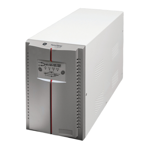
This manual suits for next models
6
Table of contents
Other GE UPS manuals

GE
GE lp33 20 series User manual

GE
GE Lanpro 33 User manual

GE
GE Uninterruptible Power Supply User manual

GE
GE TLE 625 UL S2 User manual

GE
GE 225 User manual

GE
GE 1000-1500-2000-3000 VA User manual

GE
GE Digital Energy LP 11 User manual

GE
GE SG 225 User manual

GE
GE TLE series 600 User manual

GE
GE Digital Energy SG 400 kVA User manual