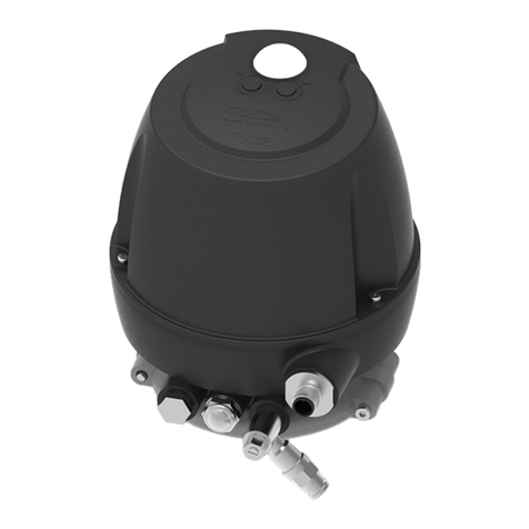
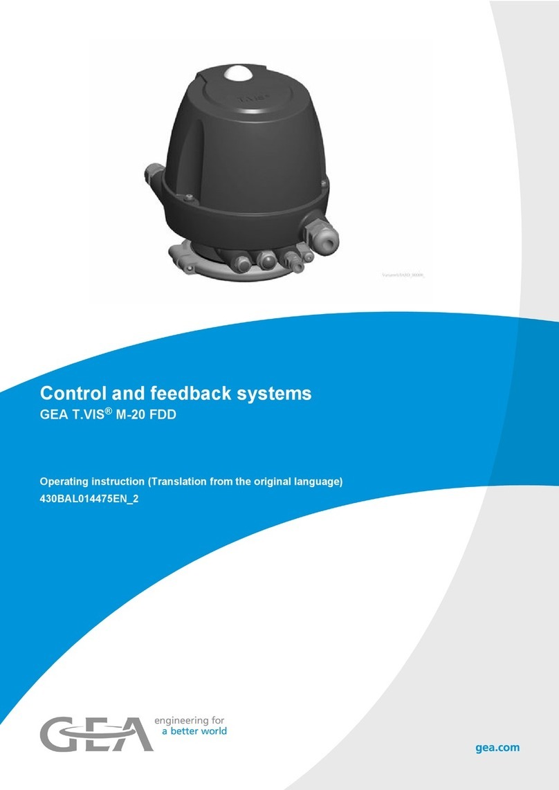
GEA T.VIS E-20 User manual

Control and feedback systems
GEA T.VIS® E-20
Operating instruction (Translation from the original language)
430BAL013985EN_6

COPYRIGHT
These Operating Instructions are the English translation of the original operating
instructions in the sense of the EU Machinery Directive. This document is
protected by copyright. All rights reserved. The document may not, in whole or in
part, be copied, reproduced, translated or reduced to an electronic medium of
machine-readable form without the express permission of GEA Tuchenhagen
GmbH.
LEGAL NOTICE
Word marks
The designations T.VIS®, VARIVENT®, ECOVENT®, STERICOM®, VESTA® und
LEFF® are protected trademarks of GEA Tuchenhagen GmbH.
We kindly request that you answer a few short questions about these instruction
manual. Use the following QR code or link to access the questionnaire:
https://www.ntgt.de/ra/s.aspx?s=367112X57707125X58087
430BAL013985EN_6
2 25.04.2023

TABLE OF CONTENTS
1 General Information 7
1.1 Information about this document 7
1.1.1 Binding Character of These Operating Instructions 7
1.1.2 Notes on the Illustrations 7
1.1.3 Symbols and Highlighting 7
1.2 Manufacturer address 8
1.3 Contact 8
1.4 EU Declaration of Conformity according to ATEX 2014/34/EU 10
1.5 Translated copy of the EU Declaration of Conformity according to ATEX 2014/34/EU 11
1.6 EU Declaration of Conformity according to EMC (2014/30/EU) and RoHs (2011/65/EU) 12
1.7 Translated copy of the EU Declaration of Conformity according to EMC (2014/30/EU) and RoHs
(2011/65/EU) 13
1.8 UKEX Declaration of Conformity for use in potentially explosive atmospheres UKSI 2016:1107 14
1.9 Translated copy of the UKEX Declaration of Conformity for use in potentially explosive atmospheres UKSI
2016:1107 15
1.10 UK Declaration of Conformity for use in potentially explosive atmospheres UKSI 2016 16
1.11 Translated copy of the UK Declaration of Conformity for use in potentially explosive atmospheres UKSI
2016 17
2 Safety 18
2.1 Intended use 18
2.1.1 Requirements for operation 18
2.1.2 Improper operating conditions 19
2.2 Operator’s Duty of Care 19
2.3 Special terms of use 20
2.4 Ambient and process temperatures 21
2.5 Avoidance of electrostatic charge 22
2.6 Subsequent changes 23
2.7 IP Protection classes 23
2.8 General safety instructions and dangers 23
2.8.1 Principles for safe operation 24
2.8.2 Environmental Protection 24
2.8.3 Electrical Equipment 24
2.9 Supplementary Regulations 25
2.10 Qualification of personnel 25
2.11 Safety equipment 26
2.11.1 Signs 26
2.12 Residual dangers 27
2.12.1 Electrostatically Endangered Components and Modules 27
2.13 Danger zones 28
3 Description 29
3.1 Design 29
3.2 Functional description 31
3.2.1 Operation Principle 31
3.2.2 Control top without solenoid valves 31
3.2.3 Control Top with Solenoid Valves 31
3.2.4 Control Top with Cap 32
3.2.5 Safety Air Exhaust/Installation Position 32
3.2.6 Openings of the outer housing to the outside atmosphere 33
4 Transport and storage 34
4.1 Storage conditions 34
4.2 Transport 34
4.2.1 Scope of supply 34
5 Technical data and operating conditions 35
5.1 Type plate 35
5.2 Technical data 37
5.2.1 ATEX/UKEX; IECEx and CCCEx designations and associated technical data 37
5.2.2 Special terms of use and safety instructions 38
5.2.3 Configuration and specification of the electrical wiring 40
5.2.4 Delivery and input data 41
Pilot valve for pneumatic valves 41
430BAL013985EN_6
25.04.2023 3

Sensor module data 42
5.2.5 General Technical Data 43
5.3 Accessories 44
5.4 Tool 45
5.5 Lubricants 45
5.6 Equipment 46
6 Assembly and installation 47
6.1 Safety precautions 47
6.2 Establishing hose connections 47
6.3 Pneumatic connections 47
6.3.1 Control Top with 1 Solenoid Valve or Without Solenoid Valve 48
6.3.2 Control top with 2 solenoid valves 49
6.3.3 Control top with 3 solenoid valves 50
6.4 Electrical connections 51
6.4.1 Overview 52
6.4.2 Specification for electrical wiring 52
6.4.3 Electrical wiring 53
Terminal strip assignment in relation to the order code 53
Terminal strip designation and separate intrinsically safe circuits 53
Wiring diagram T.VIS E-20 56
Execution and verification of the connection of internal and external circuits 57
6.5 Visual Display 57
6.5.1 Illuminated dome 58
6.6 Mounting the control top to different valves 58
6.6.1 Mounting VARIVENT Valve or STERICOM Valve Types N_A/D, R 60
6.6.2 Mounting to a Butterfly Valve T-smart 8000 62
6.6.3 Mounting to a Butterfly Valve T-smart 7 and a Mixproof Butterfly Valve T-smart 9 64
6.6.4 Mounting to ECOVENT Valves N_ECO and W_ECO 66
6.6.5 Mounting to VESTA Valve H_A/M 68
6.6.6 Mounting to Valve N_/E or W_/E or STERICOM Valve 70
6.6.7 Fitting to an ASEPTOMAG Valve 72
6.6.8 Replacing Control Tops 73
7 Start-up 74
7.1 Safety precautions 74
7.2 Switching On Control Air and Operating Voltage 74
7.3 Checking Valve Actuation 74
7.4 Service Function 75
7.5 Adjusting sensors on the control top 76
7.5.1 Spring-closing valves 77
7.5.2 Spring-opening valves 79
8 Operation and control 85
8.1 Safety precautions 85
9 Cleaning 86
9.1 Cleaning 86
10 Servicing 87
10.1 Safety instructions 87
10.2 Inspections 89
10.3 Disassembly 90
10.3.1 Removing the Control Top from the Valve 90
10.3.2 Dismantling the Control Top into its Components 90
Variants of the Control Top 90
Removing the Cap 91
Removing the Solenoid Valves and the Valve Plate 92
Removing the sensor module 93
Removing the pneumatic block 93
10.4 Installation 94
10.4.1 Install pneumatic and external connections 95
10.4.2 Fitting the Pneumatic Block 95
10.4.3 Mounting the sensor module 97
10.4.4 Mount solenoid valves and valve plates 97
10.4.5 Connect internal wiring 98
10.5 Maintenance 100
430BAL013985EN_6
4 25.04.2023

10.5.1 Replacing the Seals on the Base 100
10.5.2 Maintenance of Sound Absorber, Filter, Non-Return Valve and Throttles 100
10.5.3 Mounting cap 101
11 Alarms 102
11.1 Malfunctions and remedies 102
12 Decommissioning 103
12.1 Safety instructions 103
12.2 Disposal 103
12.2.1 General notes 103
13 Spare parts list - control top T.VIS E-20 104
14 Dimension sheet - control top T.VIS E-20 108
15 Appendix 110
15.1 Lists 110
15.1.1 Abbreviations and terms 110
430BAL013985EN_6
25.04.2023 5

430BAL013985EN_6
6 25.04.2023

1 General Information
1.1 Information about this document
The present instruction manual are part of the user information for the
component. The instruction manual contains all the information you need to
transport, install, commission, operate and carry out maintenance for the
component.
These operating instructions serve to describe the control top T.VIS E-20, which
fulfils the requirements of:
•ATEX (2014/34/EU) *: EU Declaration of Conformity
•UKEX Directive 2016 No. 1107
•IECEx*: Certificate of conformity (accessible via database eww.iecex.com)
•CCCEx certificate*
* The T.VIS E-20 must be ordered according to the required approvals.
1.1.1 Binding Character of These Operating Instructions
These Operating Instructions contain the manufacturer's instructions to the
operator of the product and to all persons who work on or use the product
regarding the procedures to follow.
Carefully read these Operating Instructions before starting any work on or using
the product. Your personal safety and the safety of the product can only be
ensured if you act as described in the Operating Instructions.
Store the Operating Instructions in such a way that they are accessible to the
operator and the operating staff during the entire life cycle of the product. When
the location is changed or the product is sold make sure you also provide the
Operating Instructions.
1.1.2 Notes on the Illustrations
The illustrations in these Operating Instructions show the product in a simplified
form. The actual design of the product can differ from the illustration. For detailed
views and dimensions of the product please refer to the design documents.
1.1.3 Symbols and Highlighting
In these Operating Instructions, important information is highlighted by symbols
or special formatting. The following examples illustrate the most important types
of highlighting.
Danger
Warning: Fatal Injuries
Failure to observe the warning can result in serious damage to health, or
even death.
► The arrow identifies a precautionary measure you have to take to avoid
the hazard.
General Information
Information about this document
430BAL013985EN_6
25.04.2023 7

Warning: Explosions
Failure to observe the warning can result in severe explosions.
► The arrow identifies a precautionary measure you have to take to avoid
the hazard.
Warning!
Warning: Serious Injuries
Failure to observe the warning can result in serious damage to health.
► The arrow identifies a precautionary measure you have to take to avoid
the hazard.
Caution!
Warning: Injuries
Failure to observe the warning can result in minor or moderate damage to
health.
► The arrow identifies a precautionary measure you have to take to avoid
the hazard.
Notice
Warning: Damage to Property
Failure to observe the warning can result in serious damage to the
component or in the vicinity of the component.
► The arrow identifies a precautionary measure you have to take to avoid
the hazard.
Carry out the following steps: = Start of a set of instructions.
1. First step in a sequence of operations.
2. Second step in a sequence of operations.
®Result of the previous operation.
®The operation is complete, the goal has been achieved.
Hint!
Further useful information.
1.2 Manufacturer address
GEA Tuchenhagen GmbH
Am Industriepark 2-10
21514 Büchen
1.3 Contact
Tel.:+49 4155 49-0
Fax:+49 4155 49-2035
General Information
Manufacturer address
430BAL013985EN_6
8 25.04.2023

1.4 EU Declaration of Conformity according to ATEX 2014/34/EU
________________________________ ________________________________
Franz Bürmann i.V. Matthias Südel
Managing Director Senior Director Engineering
EU Declaration of Conformity according to ATEX (2014/34/EU)
Manufacturer:
GEA Tuchenhagen GmbH
Am Industriepark 2-10
21514 Büchen, Germany
We hereby declare that the devices named below
Model:
T.VIS®
Type:
E-20
due to their design and construction as well as in the versions sold by us, meet the basic safety and health requirements
of the following guideline:
Relevant EC directives:
Identification:
2014/34/EU
0539
ATEX
UL 21 ATEX 2348X
II 2G Ex ia IIC T4…T5 Gb
II 2D Ex tb IIIC T85°C Db
IECEx ULD 22.0009X
Applicable harmonized standards, in
particular:
Other applied standards
and technical specifications:
EN IEC 60079-0:2018
EN 60079-11: 2012
EN 60079-31: 2014
EN 61000-6-2: 2005
EN 61000-6-4: 2007 + A1:2011
TRGS 727:2016-01
Remarks:
• The notified body UL International Demko A/S has carried out an EC type examination and issued
the following certificate: UL 21 ATEX 2348X
• The ATEX operating instructions including the intended use and safety instructions defined therein
must be observed.
• Electrostatic charge must be avoided. Ensure the grounding of the T.VIS E-20 and valve
• Process- and media temperature higher than permissible ambient temperature must not lead to
inadmissible ambient temperature
• Special conditions of use as defined in the operating manual must be observed
Person authorized for compilation and handover of technical
documentation:
GEA Tuchenhagen GmbH
CE-Documentation officer
Am Industriepark 2-10
21514 Büchen, Germany
Büchen, 28 February 2023
-10°C ≤ Ta ≤ +42°C
-10°C ≤ Ta ≤ +38°C
General Information
EU Declaration of Conformity according to ATEX 2014/34/EU
430BAL013985EN_6
10 25.04.2023

1.5 Translated copy of the EU Declaration of Conformity according to ATEX 2014/34/EU
Manufacturer: GEA Tuchenhagen GmbH
Am Industriepark 2-10
21514 Büchen, Germany
We hereby declare that the devices named below
Model: Control top T.VIS®
Type: E-20
due to its design and construction as well as in the versions sold by us, meet the basic safety and health requirements of the following
guideline:
Relevant EC directives: 2014/34/EU ATEX
Identification 0539
UL 21 ATEX 2348X
II 2G Ex ia IIC T4…T5 Gb -10°C ≤ Ta ≤ +42°C
II 2D Ex tb IIIC T85°C Db -10°C ≤ Ta ≤ +38°C
IECEx ULD 22.0009X
Applicable harmonized standards, in particular: EN IEC 60079-0: 2018
EN 60079-11: 2012
EN 60079-31: 2014
EN 61000-6-2: 2005
EN 61000-6-4: 2007 + A1:2011
Other applied standards and technical specifications: TRGS 727: 2016-01
Remarks: •The named body of UL International Demko A/S has carried out an EC type examination and issued
the following certificate: UL 21 ATEX 2348X.
•The ATEX instructions including the intended use and safety instructions defined therein must be
observed.
•Electrostatic charge must be avoided. It must be ensured that the valve and the control top are
grounded.
•Process and media temperatures above the permissible ambient temperature must not lead to an
impermissible ambient temperature.
•The particular application conditions according to the operating instructions must be observed.
Person authorised for compilation and handover of technical
documentation:
GEA Tuchenhagen GmbH
CE Documentation Officer
Am Industriepark 2-10
21514 Büchen, Germany
Büchen, 28 February 2023
Franz Bürmann
Managing Director by order Matthias Südel
Senior Director Engineering
General Information
Translated copy of the EU Declaration of Conformity according to ATEX 2014/34/EU
430BAL013985EN_6
25.04.2023 11

1.6 EU Declaration of Conformity according to EMC (2014/30/EU) and RoHs
(2011/65/EU)
EU Declaration of Conformity according to EMC (2014/30/EU) and RoHs (2011/65/EU)
Manufacturer:
GEA Tuchenhagen GmbH
Am Industriepark 2-10
21514 Buechen, Germany
Hereby, we declare that the machine designated in the following
Model:
Control top T.VIS®
Type:
E-20
by virtue of its design and construction and in the versions placed on the market by us, complies with the essential health
and safety requirements of the following directive:
Relevant EC directives:
2014/30/EU
2011/65/EU
EMC
RoHS
Applicable harmonized standards, in
particular:
Other applied standards
and technical specifications:
EN IEC 61000-6-2: 2019
DIN EN 61000-6-4: 2011-09
DIN EN 61326-1:2013
EN 62026-2: 2013
Remarks:
• The above-mentioned standards have been taken into account in accordance with
the respective scope of application
Person authorised for compilation and handover of technical
documentation:
GEA Tuchenhagen GmbH
CE Documentation Officer
Am Industriepark 2-10
21514 Buechen, Germany
Büchen, 28 February 2023
________________________________ ________________________________
Franz Bürmann i.V. Matthias Südel
Managing Director Senior Director Engineering
General Information
EU Declaration of Conformity according to EMC (2014/30/EU) and RoHs (2011/65/EU)
430BAL013985EN_6
12 25.04.2023

1.7 Translated copy of the EU Declaration of Conformity according to EMC (2014/30/EU)
and RoHs (2011/65/EU)
Manufacturer: GEA Tuchenhagen GmbH
Am Industriepark 2-10
21514 Buchen, Germany
We hereby declare that the devices named below
Model: Control top T.VIS®
Type: E-20
due to its design and construction as well as in the versions sold by us, meet the basic safety and health requirements of the following
guideline:
Relevant EC directives: 2014/30/EU EMC
2011/65/EU RoHS
Applicable harmonized standards, in particular: EN IEC 61000-6-2: 2019
DIN EN 61000-6-4: 2011-09
Other applied standards and technical specifications: DIN EN 61326-1:2013
EN 62026-2: 2013
Remarks: •The standards stated have been taken into consideration according to the respective application area.
Person authorised for compilation and handover of technical
documentation:
GEA Tuchenhagen GmbH
CE Documentation Officer
Am Industriepark 2-10
21514 Büchen, Germany
Büchen, 28 February 2023
Franz Bürmann
Managing Director by order Matthias Südel
Senior Director Engineering
General Information
Translated copy of the EU Declaration of Conformity according to EMC (2014/30/EU) and RoHs (2011/65/EU)
430BAL013985EN_6
25.04.2023 13

1.8 UKEX Declaration of Conformity for use in potentially explosive atmospheres UKSI
2016:1107
________________________________ ________________________________
Franz Bürmann i.V. Matthias Südel
Managing Director Senior Director Engineering
UK- Declaration of Conformity for use in Potentially Explosive Atmospheres UKSI 2016:1107
Manufacturer:
GEA Tuchenhagen GmbH
Am Industriepark 2-10
21514 Büchen, Germany
We hereby declare that the devices named below
Model:
Control top T.VIS®
Type:
E-20
due to their design and construction as well as in the versions sold by us, meet the basic safety and health requirements
of the following guideline:
Relevant UK directives:
Identification:
UKSI
2016:1107
0843
UKEX
UL 22UKEX2718X
II 2G Ex ia IIC T4…T5 Gb
II 2D Ex tb IIIC T85°C Db
Applicable harmonized standards, in
particular:
Other applied standards
and technical specifications:
EN IEC 60079-0:2018
EN 60079-11: 2012
EN 60079-31: 2014
TRGS 727:2016-01
Remarks:
• The notified body UL International Demko A/S has carried out an UK type examination and issued
the following certificate: UL 22 UKEX 2718X
• The UKEX operating instructions including the intended use and safety instructions defined therein
must be observed.
• Electrostatic charge must be avoided. Ensure the grounding of the T.VIS E-20 and valve
• Process- and media temperature higher than permissible ambient temperature must not lead to
inadmissible ambient temperature
• Special conditions of use as defined in the operating manual must be observed
Person authorized for compilation and handover of technical
documentation:
GEA Tuchenhagen GmbH
CE-Documentation officer
Am Industriepark 2-10
21514 Büchen, Germany
Büchen, 28 February 2023
-10°C ≤ Ta ≤ +42°C
-10°C ≤ Ta ≤ +38°C
General Information
UKEX Declaration of Conformity for use in potentially explosive atmospheres UKSI 2016:1107
430BAL013985EN_6
14 25.04.2023

1.9 Translated copy of the UKEX Declaration of Conformity for use in potentially
explosive atmospheres UKSI 2016:1107
Manufacturer: GEA Tuchenhagen GmbH
Am Industriepark 2-10
21514 Buchen, Germany
We hereby declare that the devices named below
Model: Control top T.VIS®
Type: E-20
due to its design and construction as well as in the versions
sold by us, meet the basic safety and health requirements of
the following guideline:
Relevant UK directives: UKSI 2016:1107 UKEX
Identification 0843
UL 22 UKEX 2718X
II 2G Ex ia IIC T4…T5 Gb -10°C ≤ Ta ≤ +42°C
II 2D Ex tb IIIC T85°C Db -10°C ≤ Ta ≤ +38°C
Applicable harmonized standards, in particular: EN IEC 60079-0: 2018
EN 60079-11: 2012
EN 60079-31: 2014
Other applied standards and technical specifications: TRGS 727: 2016-01
Remarks: •The named body of UL International Demko A/S has carried out a UK type examination and issued
the following certificate: UL 21 UKEX 2718X.
•The UKEX instructions including the intended use and safety instructions defined therein must be
observed.
•Electrostatic charge must be avoided. It must be ensured that the valve and the control top E-20 are
grounded.
•Process and media temperatures above the permissible ambient temperature must not lead to an
impermissible ambient temperature.
•The particular application conditions according to the operating instructions must be observed.
Person authorised for compilation and handover of technical
documentation:
GEA Tuchenhagen GmbH
CE Documentation Officer
Am Industriepark 2-10
21514 Büchen, Germany
Büchen, 28 February 2023
Franz Bürmann
Managing Director by order Matthias Südel
Senior Director Engineering
General Information
Translated copy of the UKEX Declaration of Conformity for use in potentially explosive atmospheres UKSI 2016:1107
430BAL013985EN_6
25.04.2023 15

1.10 UK Declaration of Conformity for use in potentially explosive atmospheres UKSI
2016
UK- Declaration of Conformity by Electromagnetic Compatibility Regulations 2016
Manufacturer:
GEA Tuchenhagen GmbH
Am Industriepark 2-10
21514 Büchen, Germany
Hereby, we declare that the machine designated in the following
Model:
Control top T.VIS®
Type:
E-20
by virtue of its design and construction and in the versions placed on the market by us, complies with the essential health
and safety requirements of the following directive:
Relevant UK legislation:
Electromagnetic Compatibility Regulations 2016
Regulations: restriction of hazardous substances (RoHS)
Applicable harmonized standards, in
particular:
Other applied standards
and technical specifications:
EN IEC 61000-6-2: 2019
EN IEC 61000-6-4: 2011-09
DIN EN 61326-1:2013
EN IEC 62026-2: 2013
Remarks:
• The above-mentioned standards have been taken into account in accordance with the
respective scope of application
Person authorised for compilation and handover of technical
documentation:
GEA Tuchenhagen GmbH
Documentation Officer
Am Industriepark 2-10
21514 Büchen, Germany
Büchen, 28 February 2023
________________________________ ________________________________
Franz Bürmann i.V. Matthias Südel
Managing Director Senior Director Engineering
General Information
UK Declaration of Conformity for use in potentially explosive atmospheres UKSI 2016
430BAL013985EN_6
16 25.04.2023

1.11 Translated copy of the UK Declaration of Conformity for use in potentially explosive
atmospheres UKSI 2016
Manufacturer: GEA Tuchenhagen GmbH
Am Industriepark 2-10
21514 Buchen, Germany
We hereby declare that the devices named below
Model: Control top T.VIS®
Type: E-20
due to its design and construction as well as in the versions sold by us, meet the basic safety and health requirements of the following
guideline:
Relevant UK directives: Regulations on electromagnetic compatibility 2016
Regulations: Restriction of hazardous substances (RoHS)
Applicable harmonized standards, in particular: EN IEC 61000-6-2: 2019
EN IEC 61000-6-4: 2011-09
Other applied standards and technical specifications: EN IEC 61326-1: 2013
EN IEC 62026-2: 2013
Remarks: •The standards stated have been taken into consideration according to the respective application area.
Person authorised for compilation and handover of technical
documentation:
GEA Tuchenhagen GmbH
CE Documentation Officer
Am Industriepark 2-10
21514 Büchen, Germany
Büchen, 28 February 2023
Franz Bürmann
Managing Director by order Matthias Südel
Senior Director Engineering
General Information
Translated copy of the UK Declaration of Conformity for use in potentially explosive atmospheres UKSI 2016
430BAL013985EN_6
25.04.2023 17

2 Safety
2.1 Intended use
The T.VIS E-20 control top can be used for the pneumatic and electrical
connection of all Tuchenhagen process valves with VARIVENT adaptation. Using
the device for any other purpose is considered contrary to its designated use.
Hint!
Correspondingly approved valve control modules and barriers must
be used for the electrical connection.
The control top T.VIS E-20 is available as
•without solenoid valve as position indicator
•with solenoid valve as control top
The control top T.VIS E-20 is completely installed on the dedicated actuator/
adapter of the process valve by means of a clamp connection. Due to the internal
air guiding system, the control air can pass directly from the control top into the
actuator on suitable process valves. For process valves which do not allow the air
to be guided internally, the control top has a connection option for supplying the
air externally via a hose.
To control different process valve functions, the T.VIS E-20 can be equipped with
up to three solenoid valves. The T.VIS E-20 is able to control a maximum of two
process valves by simultaneous actuation of a maximum of two solenoid valves.
With T.VIS E-20 the following can be carried out for all valves:
•monitoring the non-actuated position of the valve disk,
•monitoring the actuated position of the valve disk,
•coloured visualization of the valve position and status via the illuminated
dome fitted on the control top.
The control top T.VIS E-20 may be used in areas where ATEX/UKEX, IECEx and
CCCEx approval is required.
The unit can be used in potentially explosive atmospheres as indicated:
•ATEX (2014/34/EU) *: EU Declaration of Conformity
•UKEX Directive 2016 No. 1107
•IECEx*: Certificate of conformity (accessible via database www.iecex.com)
•CCCEx certificate*
* The T.VIS E-20 must be ordered according to the required approvals.
Hint!
The manufacturer will not accept any liability for damage resulting
from any use of the valve which is not in accordance with the
designated use of the valve. The risk is borne solely by the operating
company.
2.1.1 Requirements for operation
Safety
Intended use
430BAL013985EN_6
18 25.04.2023

The prerequisite for reliable and safe operation of the component is proper
transportation and storage as well as professional installation and assembly.
Operating the unit within the limits of its designated use also involves adhering to
the operating, inspection and maintenance instructions.
2.1.2 Improper operating conditions
The operational safety of the component can not be guaranteed under improper
operating conditions. Therefore avoid improper operating conditions.
The operation of the component is not permitted if:
•Persons or objects are in the danger zone.
•Safety devices are not working or were removed.
•Malfunctions have been detected on the component.
•Damage to the component has been detected.
•Maintenance intervals have been exceeded.
2.2 Operator’s Duty of Care
The operating company of the component has a special responsibility for the
proper and safe handling of the component within their company. Only use the
component when it is in perfect operating condition in order to prevent danger to
persons and property.
This operating manual contains information that you and your employees need
for safe operation over the life of the component. Be sure to read these Operating
Instructions carefully and ensure that the measures described here are observed.
The operator's duty of care includes planning the necessary safety measures and
monitoring that these measures are observed. The following principles apply:
•Only qualified personnel may work on the component.
•The operating company must authorize personnel to carry out the relevant
tasks.
•Order and cleanliness must be maintained at the work stations and in the
entire area surrounding the component.
•Personnel must wear suitable work clothing and personal protective
equipment. As the operating company must ensure that work clothing and
personal protective equipment are used.
•Inform personnel regarding any properties of the product which might pose a
health risk and the preventative measures to be taken.
•Have a qualified first-aid representative on call during the operation. This
person must be able to initiate any necessary first-aid measures in case of an
emergency.
•Clearly define procedures, competences and responsibilities for those
working in the area of the component. Everybody must know what to do in
case of an emergency. Instruct the staff in this respect at regular intervals.
Safety
Operator’s Duty of Care
430BAL013985EN_6
25.04.2023 19

•The signs on the component must always be complete and easy to read.
Check, clean and replace the signs as necessary at regular intervals.
•Observe the Technical Data specified and the limits of use!
Hint!
Carry out regular checks. This way you can ensure that these
measures are actually observed.
2.3 Special terms of use
Special terms of use and technical data must be observed.
Failure to observe the conditions terms of use may result in severe
explosions.
► Special conditions of use marked with the following triangle exclamation
mark must be observed.
► Additional technical data and special conditions as described in chapter 5
must be observed.
Special precautions are required to reduce the risk from electrostatic discharge. See installation/
operating instructions:
When used for a Group III (dust) application, the surface of the housing may be affected by
electrostatic charge and become a source of ignition in low relative humidity applications <~30%,
humidity if the surface is relatively free of surface contaminants, such as dirt, dust or oil.
Information on protection against ignition hazards due to electrostatic discharge can be found in
IEC EN TR50404 and IEC TS 60079-32-1. The surface should only be cleaned with a damp
cloth.
The applicable ambient temperature must be maintained by reading and understanding the user
manual, taking into account the temperature of the process medium.
The unit is designed and certified for simultaneous actuation of a maximum of two solenoid
valves. The simultaneous operation of more than two solenoid valves will increase the
temperature to a critical and non-certified level.
Cable glands are certified and specified in the test reports and must be used as intended.
The cable glands must be certified at least according to ATEX/UKEX and IECEx IP65.
Special precautions are required to reduce the risk from electrostatic discharge. See installation/
operating instructions.
Safety
Special terms of use
430BAL013985EN_6
20 25.04.2023
Table of contents
Other GEA Control System manuals
Popular Control System manuals by other brands

Guardian
Guardian EMC3B manual

Stuart Turner
Stuart Turner STUART SPU 135 Midi Installation, operation & maintenance instructions

Bosch
Bosch FHP UPM I Installation and operation manual

Douglas Lighting Controls
Douglas Lighting Controls LitePak WPAK-33518-S Technical data

Key Digital
Key Digital FATCAT Series Setup guide

Stagnoli
Stagnoli H230 manual