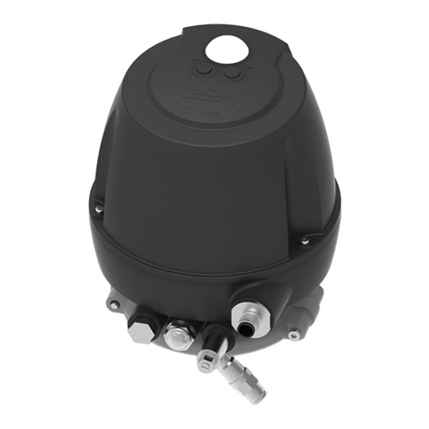
GEA D 10 User instructions

Mechanische Trenntechnik / GEA Westfalia Separator
Settings and malfunctions
Designation
Control system for separators with self-cleaning bowl
Type
D 10
No.
8555-9201-000
Edition
0109

2 8555-9201-000/ 0109
Mechanical Separation / GEA Westfalia Separator
TRANSLATION OF ORIGINAL MANUAL
Subject to modification!
The authors are always grateful for comments and suggestions for improving
the documentation. They can be addressed to:
Mechanical Separation
GEA Westfalia Separator GmbH
Werner-Habig-Straße 1 · D-59302 Oelde
Tel.: +49 (0) 25 22 / 77-0 · Fax: +49 (0) 25 22 / 77-17 78
ws.systems@geagroup.com · www.westfalia-separator.com

8555-9201-000/ 0109 3
Mechanical Separation / GEA Westfalia Separator
For your safety
•
Take special care when carrying out operations marked with this
symbol -
otherwise danger to life!
•Strictly adhere to instructions marked with this symbol.
This avoids damage to the separator and other equipment.
Note:
•This symbol is not a safety precaution but rather a reference to infor-
mation which help to better understand the separator or plant compo-
nents and the processes.
•Refer to the separator and control manual.

4 8555-9201-000/ 0109
Mechanical Separation / GEA Westfalia Separator
1Timer overview 7
1.1 Timer list OSD 6-...-… ............................................................................. 8
1.2 Timer list OSD 18-...-… ........................................................................... 9
1.3 Timer list OSD 35-...-… .........................................................................10
1.4 Timer list OSD 60-...-… .........................................................................11
1.5 Timer description -T00 to T62 ............................................................12
2Counter overview 15
2.1 Counters and time recording .................................................................15
2.1.1 Settings .................................................................................................. 16
2.1.2 Description ............................................................................................. 17
2.2 Alarm settings for temperature and ejection monitoring ........................ 18
3Process sequence 19
3.1 Program logic -Diagram ...-0136-... .................................................... 19
3.1.1 Diagram ...-0136-... Legend components ............................................. 21
3.1.2 Diagram ...-0136-... Legend line/tank ................................................... 22
3.1.3 Diagram ...-0136-... -Chapter "A”........................................................23
3.1.4 Diagram ...-0136-... -Chapter “B”........................................................24
3.1.5 Diagram ...-0136-... -Chapter “C”........................................................ 25
3.1.6 Diagram ...-0136-... -Chapter “D”........................................................ 26
3.1.7 Diagram …-0136-… -Chapter “E“.......................................................27
3.2 Program logic -Diagram ...-0196-... .................................................... 28
3.2.1 Diagram …-0196-… -Legend components......................................... 29
3.2.2 Diagram …-0196-… -Legend components......................................... 30
3.2.3 Diagram ...-0196-... -Chapter “A”........................................................31
3.2.4 Diagram ...-0196-... -Chapter “B”........................................................32
3.2.5 Diagram ...-0196-... -Chapter “C”........................................................ 33
3.2.6 Diagram ...-0196-... -Chapter “D”........................................................ 34
3.2.7 Diagram …-0196-… -Chapter “E“.......................................................35
3.3 Program logic -Diagram ...-91-... ........................................................ 36
3.3.1 Diagram ...-91-... Legend modules .......................................................37
3.3.2 Diagram ...-91-... Legend lines/tank ..................................................... 38
3.3.3 Diagram ...-91-... -Chapter “A”............................................................ 39
3.3.4 Diagram ...-91-... -Chapter “B”............................................................40
3.3.5 Diagram ...-91-... -Chapter “C”............................................................ 41
3.3.6 Diagram ...-91-... -Chapter “D”............................................................ 42
3.3.7 Diagram ...-91-... -Chapter “E”............................................................43
Trouble shooting 45
4.1 Alarm #00 -Know-how protection ....................................................... 46
4.2 Alarm #01 -Motor protection ...............................................................47
4.3 Alarm #05 -TAL product feed.............................................................. 48
4.4 Alarm #06 -TAH product feed .............................................................49
4.5 Alarm #07 -Ejection monitoring........................................................... 50
4.6 Alarm #08 -LAHH sludge tank ............................................................ 51

8555-9201-000/ 0109 5
Mechanical Separation / GEA Westfalia Separator
4.7 Alarm #09 -feed pump fault ................................................................52
4.8 Alarm #10 -Sludge pump fault ............................................................ 53
4.9 Alarm #11 -Vibration stage 1 (option)................................................ 54
4.10 Alarm #12 -Vibration stage 2 (option)................................................ 55
4.11 Alarm #13 -Fault series operation (option) ......................................... 56
4.12 Alarm #15 -WMS system fault ............................................................ 57
4.13 Alarm #18 -Bowl monitoring................................................................ 58
4.14 Alarm #19 -Separator motor OFF....................................................... 59
4.15 Alarm #21 -WMS sensor fault (option) ............................................... 60
4.16 Alarm #22 -Sludge pump running time too long .................................61
4.17 Alarm #23 -WMS activates too often ..................................................62
4.18 Alarm #27 -Maintenance interval........................................................ 63
4.19 Warning #28 -Warning water content .................................................64
4.20 Alarm #33 -Ejection monitoring (option) ............................................. 65
4.21 Alarm #34 -Bowl monitoring (option) .................................................. 66
4.22 Alarm #35 -Separator start monitoring (option) .................................. 67
4.23 Alarm #36 -Belt monitoring (option) .................................................... 68
4.24 Alarm #37 -Max. speed monitoring (option) .......................................69
4.25 Alarm #38 -Min. speed monitoring (option) ........................................70
4.26 Alarm #39 -PT1 function (option)........................................................71
4.27 Alarm #40 -No water seal ................................................................... 72
4.28 Alarm #41 -Min. separating time.........................................................73
4.29 Alarm #42 -SMS sensor fault (option) ................................................ 74
4.30 Alarm #43 -PT2 sensor active when idling .........................................75
4.31 Alarm #44 -PAL1 clean oil discharge ................................................. 76
4.32 Alarm #45 -PAH1 clean oil discharge................................................. 77
4.33 Alarm #46 -Emergency-Off ................................................................. 78
4.34 Alarm #48 -Water discharge ............................................................... 79
5Alarm Simulation and Test 81
5.1 Alarms #01 to #10..................................................................................82
5.2 Alarms #11 to #20..................................................................................83
5.3 Alarms #21 to #30..................................................................................84
5.4 Alarms #31 to #40..................................................................................85
5.5 Alarms #41 to #50..................................................................................86
6Ejection / bowl monitoring 87
6.1 Graphic representation of an ejection / bowl monitoring -
motor current ......................................................................................... 88
6.2 Graphic representation of an ejection / bowl monitoring - speed .......... 89
7Bowl volume / speed settings 91
7.1 Bowl volume........................................................................................... 92
7.2 Speed settings ....................................................................................... 92

6 8555-9201-000/ 0109
Mechanical Separation / GEA Westfalia Separator
N
N
o
o
t
t
e
e
N
No
ot
te
es
s
N
No
ot
ti
iz
ze
en
n
A
An
no
ot
ta
ac
ci
io
on
ne
es
s
Д
Дл
ля
я
з
за
ап
пи
ис
се
ей
й
M
Mu
ui
is
st
ti
ii
in
np
pa
an
no
ot
t
Σ
Ση
ημ
με
ει
ιώ
ώσ
σε
ει
ις
ς
N
No
ot
ta
at
te
er
r
N
No
ot
te
es
s
N
No
ot
te
e

8555-9201-000/ 0109 7
Mechanical Separation / GEA Westfalia Separator
1 Timer overview
1.1 Timer list OSD 6-...-… ............................................................................. 8
1.2 Timer list OSD 18-...-… ........................................................................... 9
1.3 Timer list OSD 35-...-… .........................................................................10
1.4 Timer list OSD 60-...-… .........................................................................11
1.5 Timer description -T00 to T62 ............................................................ 12

8 8555-9201-000/ 0109
Mechanical Separation / GEA Westfalia Separator
1.1 Timer list OSD 6-...-…
Timer
Control D10
Remarks
Separator model
Complete text Display text
OSD 6
-0136-
-0196-
-91-
HFO
LO
LO / (M)DO / HFO
sec
T00 Partial ejection
Partial ejection
1.5 1.5 1.5
T01
Displacement
Displacement
8 8 8
T02
Filling
Filling
8 8 8
T03
Waiting
Waiting
5 5 5
T04
Total ejection
Total ejection
2 2 2
T05
Speed recovery after total ejection
Speed recov. total
8 8 8
T06
Closing water impulse
Closingwater imp
0.08 0.08 0.08
T07
Alarm delay
Alarm delay
10 10 10
T08
Waiting after displacement
Wait aft.displac
5 5 5
T09
Waiting after filling
Wait aft.filling
5 5 5
T10
Separator starting
Sep. runup
240 240 240
T11
Alarm bridging
Alarm-bridging
30 30 30
T12
Waiting after 1st ejection
Wait aft 1. Eject
5 5 5
T13
Speed recovery after partial ejection
Speed rec.part Speed
8 8 8
T14 Closing water interval
Closing Interval
600 600 600
T15
Circulation valve close
Circ.valve clos
60 0 0
T16
Circulation valve open
Circ.valve open
5 0 0
T17
Water content bridging
Water cont. bridging
0 600 0
T18
Sludge tank alarm delay
LSHH-Sludgetank
10 10 10
T19
Water impulse at start
Water pulse bef. start
3 3 3
T20
Separation
Separation
no password
7 200 7 200 7 200
T21
Min. separation time
Min-Sep.-Time
600 0 0
T22
High water content
High water cont.
10 10 0
T23
Feed pump delay
Feed pump delay
300 300 300
T24
Sludge pump delay off
Sludgep.delay
60 60 60
T25
Vibration 1 - delay
Vibro 1
option
180 180 180
T26
Vibration 2 -delay
Vibro 2
option
2 2 2
T27
SMS low pressure delay
SMS PSL delay
10 0 0
T28
Ejection monitoring
Ejection monitor
5 5 5
T29
Brake for separator
Brake for Sep.
option
300 300 300
T30
Free
Free
T31
Free
Free
T32
WMS-Mode
WMS-Mode
0 5 400 0
T33
SMS-Mode
SMS-Mode
0 120 0
T34
Circuit valve delay
Circuirt v. delay
0 10 0
T35
Water seal broken
Water.Seal
0 10 0
T36
SMS Press.Check
SMS Press.Check
0 1 0
T37
SMS Waiting
SMS Waiting
0 3 0
T38
WMS sensor flushing
WMS sens. flushing
0 20 0
T39
Separator motor off
Separator off
1 800 1 800 1 800
T40
CU sludge pump on
CE sludgepump on
option
60 60 60
T41
CU sludge pump delay
CU-Sl.Pu delay
option
600 600 600
T42
Free
Free
- - -
T43
Free
Free
- - -
T44
SMS sensor check
SMS sensor check
option
35 35 0
T45
WMS sensor check
WMS sensor check
option
300 20 0
T46
Free
Free
- - -
T47
Min.SMS Time
Min. SMS Time
0 18 0
T60
Start impulse
Start impulse
option
10 10 0
T61
Sensor interval
Sensor interval
option
2 2 0
T62
Sensor impulse
Sensor impulse
option
1 1 0

8555-9201-000/ 0109 9
Mechanical Separation / GEA Westfalia Separator
1.2 Timer list OSD 18-...-…
Timer
Control D10
Remarks
Separator model
Complete text Display text
OSD 18
-0136-
-0196-
-91-
HFO
LO
LO / (M)DO / HFO
secs
T00 Partial ejection
Partial ejection
2 2 2
T01
Displacement
Displacement
13 13 13
T02
Filling
Filling
13 13 13
T03
Waiting
Waiting
5 5 5
T04
Total ejection
Total ejection
2.5 2.5 2.5
T05
Speed recovery after total ejection
Speed recov. total
10 10 10
T06
Closing water impulse
Closingwater imp
0.1 0.1 0.1
T07
Alarm delay
Alarm delay
10 10 10
T08
Waiting after displacement
Wait aft.displac
5 5 5
T09
Waiting after filling
Wait aft.filling
5 5 5
T10
Separator starting
Sep. runup
240 240 240
T11
Alarm bridging
Alarm-bridging
30 30 30
T12
Waiting after 1st ejection
Wait aft 1. Eject
5 5 5
T13
Speed recovery after partial ejection
Speed rec.part Speed
10 10 10
T14
Closing water interval
Closing Interval
600 600 600
T15
Circulation valve close
Circ.valve clos
60 0 0
T16
Circulation valve open
Circ.valve open
5 0 0
T17
Water content bridging
Water cont. bridging
0 600 0
T18
Sludge tank alarm delay
LSHH-Sludgetank
10 10 10
T19
Water impulse at start
Water pulse bef. start
3 3 3
T20
Separation
Separation
no password
7 200 7 200 7 200
T21
Min. separation time
Min-Sep.-Time
600 0 0
T22
High water content
High water cont.
15 15 0
T23
Feed pump delay
Feed pump delay
300 300 300
T24
Sludge pump delay off
Sludgep.delay
60 60 60
T25
Vibration 1 - delay
Vibro 1
option
180 180 180
T26
Vibration 2 -delay
Vibro 2
option
2 2 2
T27
SMS low pressure delay
SMS PSL delay
10 0 0
T28
Ejection monitoring
Ejection monitor
5 5 5
T29
Brake for separator
Brake for Sep.
option
600 600 600
T30
Free
Free
T31
Free
Free
T32
WMS-Mode
WMS-Mode
0 5 400 0
T33
SMS-Mode
SMS-Mode
0 120 0
T34
Circuit valve delay
Circuirt v. delay
0 10 0
T35
Water seal broken
Water.Seal
0 10 0
T36
SMS Press.Check
SMS Press.Check
0 1 0
T37
SMS Waiting
SMS Waiting
0 3 0
T38
WMS sensor flushing
WMS sens. flushing
0 20 0
T39
Separator motor off
Separator off
1 800 1 800 1 800
T40
CU sludge pump on
CE sludgepump on
option
60 60 60
T41
CU sludge pump delay
CU-Sl.Pu delay
option
600 600 600
T42
Free
Free
- - -
T43
Free
Free
- - -
T44
SMS sensor check
SMS sensor check
option
60 60 0
T45
WMS sensor check
WMS sensor check
option
300 20 0
T46
Free
Free
- - -
T47
Min.SMS Time
Min. SMS Time
0 7 0
T60
Start impulse
Start impulse
option
20 20 0
T61
Sensor interval
Sensor interval
option
2 2 0
T62
Sensor impulse
Sensor impulse
option
1 1 0

10 8555-9201-000/ 0109
Mechanical Separation / GEA Westfalia Separator
1.3 Timer list OSD 35-...-…
Tim e r
Control D10
Remarks
Separator model
Complete text Dis p la y te xt
OS D 35
-0136-
-0196-
-91-
HFO
LO
LO / (M)DO / HFO
sec
T00 Partial ejection
Partial ejection
3 3 3
T01
Displacement
Displacement
35 35 35
T02
Filling
Filling
35 35 35
T03
Waiting
Waiting
5 5 5
T04
Total ejection
Total ejection
3.5 3.5 3.5
T05
Speed recovery after total ejection
Speed recov. total
15 15 15
T06
Closing water impulse
Closingwater imp
0.1 0.1 0.1
T07
Alarm delay
Alarm delay
10 10 10
T08
Waiting after displacement
Wait aft.displac
5 5 5
T09
Waiting after filling
Wait aft.filling
5 5 5
T10
Separator starting
Sep. runup
480 480 480
T11
Alarm bridging
Alarm-bridging
30 30 30
T12
Waiting after 1st ejection
Wait aft 1. Eject
5 5 5
T13
Speed recovery after partial ejection
Speed rec.part Speed
15 15 15
T14
Closing water interval
Closing Interval
600 600 600
T15
Circulation valve close
Circ.valve clos
60 0 0
T16
Circulation valve open
Circ.valve open
5 0 0
T17
Water content bridging
Water cont. bridging
0 600 0
T18
Sludge tank alarm delay
LSHH-Sludgetank
10 10 10
T19
Water impulse at start
Water pulse bef. start
3 3 3
T20
Separation
Separation
no password
7 200 7 200 7 200
T21 Min. separation time
Min-Sep.-Time
600 0 0
T22
High water content
High water cont.
20 20 0
T23
Feed pump delay
Feed pump delay
300 300 300
T24
Sludge pump delay off
Sludgep.delay
80 80 80
T25
Vibration 1 - delay
Vibro 1
option
180 180 180
T26
Vibration 2 -delay
Vibro 2
option
2 2 2
T27
SMS low pressure delay
SMS PSL delay
10 0 0
T28
Ejection monitoring
Ejection monitor
5 5 5
T29
Brake for separator
Brake for Sep.
option
900 900 900
T30
Free
Free
T31 Free
Free
T32
WMS-Mode
WMS-Mode
0 5 400 0
T33
SMS-Mode
SMS-Mode
0 120 0
T34
Circuit valve delay
Circuirt v. delay
0 10 0
T35
Water seal broken
Water.Seal
0 10 0
T36
SMS Press.Check
SMS Press.Check
0 2 0
T37
SMS Waiting
SMS Waiting
0 3 0
T38
WMS sensor flushing
WMS sens. flushing
0 20 0
T39
Separator motor off
Separator off
1 800 1 800 1 800
T40
CU sludge pump on
CE sludgepump on
option
60 60 60
T41
CU sludge pump delay
CU-Sl.Pu delay
option
600 600 600
T42
Free
Free
- - -
T43
Free
Free
- - -
T44
SMS sensor check
SMS sensor check
option
120 120 0
T45
WMS sensor check
WMS sensor check
option
300 20 0
T46
Free
Free
- - -
T47
Min.SMS Time
Min. SMS Time
0 3.5 0
T60
Start impulse
Start impulse
option
60 60 0
T61
Sensor interval
Sensor interval
option
2 2 0
T62
Sensor impulse
Sensor impulse
option
1 1 0

8555-9201-000/ 0109 11
Mechanical Separation / GEA Westfalia Separator
1.4 Timer list OSD 60-...-…
Tim e r
Control D10
Remarks
Separator model
Complete text Dis p la y te xt
OS D 60
-0136-
-0196-
-91-
HFO
LO
LO / (M)DO / HFO
sec
T00 Partial ejection
Partial ejection
3 3 3
T01
Displacement
Displacement
100 100 100
T02
Filling
Filling
100 100 100
T03
Waiting
Waiting
5 5 5
T04
Total ejection
Total ejection
3.5 3.5 3.5
T05
Speed recovery after total ejection
Speed recov. total
20 20 20
T06
Closing water impulse
Closingwater imp
0.1 0.1 0.1
T07
Alarm delay
Alarm delay
10 10 10
T08
Waiting after displacement
Wait aft.displac
5 5 5
T09
Waiting after filling
Wait aft.filling
5 5 5
T10
Separator starting
Sep. runup
600 600 600
T11
Alarm bridging
Alarm-bridging
30 30 30
T12
Waiting after 1st ejection
Wait aft 1. Eject
5 5 5
T13
Speed recovery after partial ejection
Speed rec.part Speed
20 20 20
T14
Closing water interval
Closing Interval
600 600 600
T15
Circulation valve close
Circ.valve clos
60 0 0
T16
Circulation valve open
Circ.valve open
5 0 0
T17
Water content bridging
Water cont. bridging
0 600 0
T18
Sludge tank alarm delay
LSHH-Sludgetank
10 10 10
T19
Water impulse at start
Water pulse bef. start
3 3 3
T20
Separation
Separation
no password
7 200 7 200 7 200
T21
Min. separation time
Min-Sep.-Time
600 0 0
T22
High water content
High water cont.
30 30 0
T23
Feed pump delay
Feed pump delay
300 300 300
T24
Sludge pump delay off
Sludgep.delay
100 100 100
T25
Vibration 1 - delay
Vibro 1
option
180 180 180
T26
Vibration 2 -delay
Vibro 2
option
2 2 2
T27
SMS low pressure delay
SMS PSL delay
10 0 0
T28
Ejection monitoring
Ejection monitor
5 5 5
T29
Brake for separator
Brake for Sep.
option
1 200 1 200 1 200
T30
Free
Free
T31
Free
Free
T32
WMS-Mode
WMS-Mode
0 5400 0
T33
SMS-Mode
SMS-Mode
0 120 0
T34
Circuit valve delay
Circuirt v. delay
0 10 0
T35
Water seal broken
Water.Seal
0 10 0
T36
SMS Press.Check
SMS Press.Check
0 2 0
T37
SMS Waiting
SMS Waiting
0 3 0
T38
WMS sensor flushing
WMS sens. flushing
0 20 0
T39
Separator motor off
Separator off
1 800 1 800 1 800
T40
CU sludge pump on
CE sludgepump on
option
60 60 60
T41
CU sludge pump delay
CU-Sl.Pu delay
option
600 600 600
T42
Free
Free
- - -
T43
Free
Free
0 0 0
T44
SMS sensor check
SMS sensor check
option
260 260 0
T45
WMS sensor check
WMS sensor check
option
300 20 0
T46
Free
Free
- - -
T47
Min.SMS Time
Min. SMS Time
0 5 0
T60
Start impulse
Start impulse
option
140 140 0
T61
Sensor interval
Sensor interval
option
2 2 0
T62
Sensor impulse
Sensor impulse
option
1 1 0

12 8555-9201-000/ 0109
Mechanical Separation / GEA Westfalia Separator
1.5 Timer description -T00 to T62
Tim e r Designation Ac t io n Des criptio n Ac tive in
-0136-
-0196-
-91-
T00
Partial ejection
Operat. water valve V3 opens.
The solids space of the bowl is partially ejected by
actuating the operating water valve V3 (option).
X X X
T01
Displacement
Displacement water valve V”
opens.
The bowl content is displaced without loss by
actuating the displacement water valve V2.
If selected in the control system, the time is calcu-
lated automatically during the sensor check.
X X X
T02
Filling
Filling water valve V2 opens.
The required water seal in the bowl is created by
actuating the filling water valve V2.
If selected in the control system, the time is calcu-
lated automatically during the sensor check.
Filling water is also active during the WMS
sensor check on HFO separators.
--- X X
T03
Waiting
Product feed valve V1 closes.
Clean oil discharge pressure
drops.
Time elapses before the displacement water func-
tion when key “Process START” has been ac-
tuated.
X X X
T04
Total ejection
Operat. water valve V3 opens.
The solids space of the bowl is emptied by actuat-
ing the operating-water valve V3.
X X X
T05
Speed recovery after
total ejection
Time to reach operating speed after speed drop
during total ejection.
X X X
T06
Closing water im-
pulse
Operat. water valve V3 opens.
Time for safety closing water to keep the bowl
closed during separation.
X X X
T07
Alarm delay
After this time has expired, the
product feed valve i closed and
an alarm is triggered.
After this time has expired, standard alarms like
PAL1/PAH1, TAL/TAH, PAH2 etc. are triggered. X X X
T08
Waiting after dis-
placement
Time for stabilizing the system after displacement.
X X X
T09
Waiting after filling
Time for stabilizing the system after filling.
---
X
X
T10
Separator starting
Press button „Separator 1“ has
been activated,
Separator motor runs up.
Time to reach the operating speed of the separator
after pressing button “Separator 1”. X X X
T11
Alarm bridging
Alarms not active.
Time to stabilize the process conditions.
X
X
X
T12
Waiting after 1st
ejection
Time to reach operating speed after speed drop
during the 1. total ejection.
X X X
T13
Speed recovery after
partial ejection
Time to reach operating speed after speed drop
during the partial ejection.
X X X
T14
Closing water interval
Time interval between two closing water pulses.
X
X
X
T15
Circulation valve
close
Circulation valve V5 closes.
Time for which the circulation valve V5 is closed.
X --- ---
T16
Circulation valve
open
Circulation valve V5 opens.
WMS sensor is active.
Time for which the circulation valve V5 is open.
The WMS sensor monitors the feeler current.
X --- ---
T17
Water content
bridging
Warning water content.
Not active.
Time to prevent a false alarm due to too much
filling water. Time starts with T20 “Separation”.
--- X ---
T18
Sludge tank alarm
delay
After this time has expired, the
product feed valve i closed and
an alarm is triggered.
Time delay for sludge tank alarm LAHH. The prod-
uct feed valve is closed and an ejection cycle is
started.
X X X
T19
Water impulse at
start
Operat. water valve V3 opens.
Time to close the bowl after reaching the operating
speed by opening the operating water valve V3.
X X X
T20
Separation
Product feed valve V1 opens.
Time to adjust the duration of the separating time.
(time interval between ejections)
X X X
T21
Min. separation time
In the case of a pressure drop
during this time, the product
feed valve V! is closed and an
alarm and an ejection are
triggered. After this time has
expired, the product feed valve
V1 is closed and an ejection is
triggered without alarm.
Time during separation in which a system pressure
drop (SMS) is evaluated as an alarm during this
time.
The time starts together with the separating time
T20. A pressure drop agter this time has expired
triggers an ejection (“self-thinker” control).
X --- ---
T22
High water content
Water discharge valve V6 is
open.
Time to trigger the alarm „WMS system error – too
much water” when the WMS sensor outputs a
water signal during the entire running time.
The SMS sensor PT2 must simultaneously output
a pressure signal.
X X ---
T23
Post-run feed pump
Feed pump is switched off
after this time has expired.
Time in which the pump continuous to run to let
the heater cool off.
X X X
T24
Post-run sludge
pump
Sludge pump is switched off
after this time has expired.
Time in which the sludge pump continues to run to
ensure that the sludge tank is emptied completely.
X X X
T25
Vibration 1 - delay
After this time has expired,
Time delay for the vibration 1 alarm which is
X
X
X

8555-9201-000/ 0109 13
Mechanical Separation / GEA Westfalia Separator
Tim e r Designation Ac t io n Des criptio n
Ac tive in
-0136-
-0196-
-91-
the product feed valve is
closed and an ejection is
triggered.
triggered in the case of a continuous signal on the
vibration measuring device.
T26
Vibration 2 -delay
After this time has expired,
the product feed valve is
closed and an alarm is trig-
gered.
– Filling water valve V2 is
opened and safety water is
fed into the bowl.
– Pneumatic brake is acti-
vated (option).
– The separator motor is
switched off immediately.
Time delay for the vibration 2 alarm which is
triggered in the case of a continuous signal on the
vibration measuring device.
X X X
T27
SMS low pressure
delay
After this time has expired,
the product feed valve is
closed and an ejection is
triggered.
The time expires when the SMS pressure has
dropped off and T21 “minimum separating time”
has elapsed. An ejection is triggered. Accumu-
lated solids in the solids space of the space has
caused the pressure drop.
X --- ---
T28
Ejection monitoring
The motor current or speed is
monitored within this time. An
alarm is triggered after this
time has expired.
The motor current or speed is monitored during
the ejection phase. If the motor current or speed
does not exceed the adjusted offset during this
time, an alrm is triggered.
X X X
T29
Brake for separator
The brake is actuated for this
time.
Time to brake the separator automatically after an
alarm “Vibration 2”.
X X X
T30
Free
T31
Free
T32
WMS-Mode
Water discharge valve V6 is
closed; it opens only when the
SMS pressure transmitter PT2
is activated.
Circulation valve V5 is closed.
Time for water content monitoring during the
separating process. The separator functions as a
purifier. --- X ---
T33
SMS-Mode
Water discharge valve V6 is
closed.
Circulation valve V5 is closed.
Time for solids space monitoring. Only the SMS
sensor PT2 is activated. The solid content of the
bowl is monitored.
--- X ---
T34
WMS press.check
Circulation valve V5 is closed.
Water discharge V6 is opened
and closes after this time has
expired.
Time to flush the WMS sensor.
--- X ---
T35
Water seal broken
Circulation valve V5 is open.
Water discharge valve V6 is
closed.
Alarm “no water seal” is trig-
gered.
Time in which the alarm “no water seal” triggers
when the WMS sensor oil and the SMS sensor
PT2 indicate pressure during the running time of
the timer. --- X ---
T36
SMS press.check
Filling water valve V2 is open.
SMS sensor PT2 is activated.
Bowl is filled with filling water pulse-wise for
checking the solids space. If the solids space is
not filled with solids, the SMS pressure switch
PT2 must output a pressure signal. If no pressure
builds up, an ejection is triggered.
X --- ---
T37
SMS Waiting
Filling water valve V2 is
closed.
SMS sensor PT2 is activated.
Time interval between two filling water pulses
during solids space monitoring. X --- ---
T38
WMS sensor flush-
ing
WMS sensor not active.
SMS sensor PT2 not acti-
vated.
Water discharge valve V6 is
open.
Time to rinse the sensor line after the first pro-
gram start and to let the surplus filling water dis-
charge. --- X ---
T39
Separator motor off
After this time has expired,
the separator motor is switch-
ed off.
Time delay to switch off the separator motor. The
function must be pre-selected in the program. X X X
T40
CU sludge pump on
Sludge pump is activated.
Time in which the sludge pump is switched on to
ensure that the sludge tank is emptied completely.
X X X
T41
CU sludge pump
delay
Sludge pump is not activated.
Time interval between two sludge pump starts.
X X X
T42
Free
T43
Free

14 8555-9201-000/ 0109
Mechanical Separation / GEA Westfalia Separator
Tim e r Designation Ac t io n Des criptio n
Ac tive in
-0136-
-0196-
-91-
T44
SMS sensor check
Water discharge valve V6 is
closed.
Circulation valve V5 is closed.
SMS sensor PT2 is activated.
Time in which the function of the SMS sensor PT2
is checked.
If no pressure signal is identified on the SMS
sensor PT2 after this time has elapsed, an alarm
“SMS sensor error” is triggered.
X X ---
T45
WMS sensor check
Lubricating oil function -
0196-:
– Water discharge valve V6
is open.
– Circulation valve V5 is
closed.
– WMS sensor is active.
Heavy oil function -0136-:
– Circulation valve function
with T15 and T16.
–
WMS sensor is active.
Time in which the function of the WMS sensor is
checked.
If no water is identified on the WMS sensor after
this time has elapsed, an alarm “WMS sensor
error” is triggered.
X X ---
T46
Free
T47
Min.SMS Time
If the SMS sensor P2T is
activated during this time, the
water discharge valve V6 is
opened for 3 seconds and the
counter Z5 “water content”
evaluates the signal.
Capacity and machine-type specific time with
which the increase in water in the product feed is
determined during WMS mode. The pressure
increase is evaluated as a function of T47 via
several successful cycles which are defined via
counter Z5 “water content”.
--- X ---
T60
Start impulse
Filling water valve V2 is open.
Time to fill the filling water into the separator bowl.
This time works before the timers T61 „sensor
pause“and T62 “sensor pulse“.
The total time is required for the automatic calcu-
lation of the timers T01 “Displacement” and T02
“Filling”. The time T60 is protected.
X X ---
T61
Sensor interval
Filling water valve V2 is
closed.
Time interval between two closing water pulses.
The time T61 is protected.
X X ---
T62
Sensor pulse
Filling water valve V2 is open.
Time to fill the filling water into the separator bowl.
This time works pulse-wise in accordance with
timer T61 “sensor pause“. The time is required for
the automatic calculation of the timers T01 “Dis-
placement” and T02” “Filling”. The time T62 is
protected.
X X ---

8555-9201-000/ 0109 15
Mechanical Separation / GEA Westfalia Separator
2 Counter overview
2.1 Counters and time recording .................................................................15
2.1.1 Settings .................................................................................................. 16
2.1.2 Description ............................................................................................. 17
2.2 Alarm settings for temperature and ejection monitoring ........................ 18

16 8555-9201-000/ 0109
Mechanical Separation / GEA Westfalia Separator
2.1 Counters and time recording
2.1.1 Settings
Separator model
OSD 60
Counter
5
5
5
10
5
TR… = Time Record
240
50
24 h
OSD 35
5
5
5
10
5
150
40
24 h
OSD 18
5
5
5
10
5
150
30
24 h
OSD 6
5
5
5
10
5
60
30
24 h
Remarks
(Act. in = actual
24h)
(Prev. in = previous
24h)
(Act. in = actual
24h)
(Prev. in = previous
24h)
Control
Text display
Z1 flush ejection g:
P: 5
A: 0
Z2 partial ejection:
P: 5
A: 0
Z3 SMS filling:
P: 3
A: 0
Z4 sensor check:
P: 10
A: 0
Z5 water content
P: 5
A: 0
WMS time
60 min
0 min
0 min
Sludge pump time
30 min
0 min
0 min
Time zero pos.
P: 24
A: 0
24 h
24 h
24 h
24 h
24 h
24 h
Max. in
Act. in
Prev. in
Max. in
Act. in
Prev. in
Complete text
Counter flush ejection
Counter partial ejection
Counter SMS filling
Counter sensor check:
Counter for water content
alarm
Time record of the WMS
time during operation
within the setpoint preset
in TR3 (24 h).
Time record of the sludge
pump operating time
within the setpoint set in
ZR3 (24 h).
Zero position of all time
records after the time set
as setpoint in TR3 (24 h).
Flush ejection
Partial ejection
SMS filling
Sensor check
Water content
WMS time
Sludge pump time
Time record zero posi-
tion
Z1
Z2
(Option)
Z3
Z4
(Option)
Z5
TR1
TR2
TR3

8555-9201-000/ 0109 17
Mechanical Separation / GEA Westfalia Separator
2.1.2 Description
No. Designation Action/status De s c rip tio n Active in
-0136- -0196- -91-
Counter (Z… or C… = Counter …)
Z1
Flush ejection
Counter for performing
a double total ejection.
Counter with which it is defined after
how many individual ejections a
double flush ejection is carried out.
X X X
Z2
(Option) Partial ejection Counter for performing
a double total ejection.
Counter with which it is defined after
how many partial ejections a double
total ejection is carried out.
X X X
Z3
SMS filling
Counter for filling wa-
ter pulses in SMS
mode after T33.
Counter with which the filling water
pulses are defined.
After expiry of the SMM mode T33 for
solids space monitoring, filling water
pulses are activated.
--- X ---
Z4
(Option)
Sensor check
Counter for sensor
check.
Counter with which it is defined after
how many ejections an SMS and
WMS check are carried out.
X X ---
Z5
Water content
Counter for SMS sen-
sor signals during the
WMS mode.
Counter which registers the SMS sen-
sor sigals PT2 which are activated
within the time T47 „min. SMS time”.
The counter is reset when the presure
signal is activated after expiry of T47
„min. SMS time”.
When the counter has run down, a
warning is output tat there is a high
water content in the product feed.
--- X ---
Time recording (TR… = Time Record …)
TR1 WMS time During separation process the time
during which the WMS sensor detects
water is recorded.
The time recording is reset after ex-
piry of TR3.
X X ---
TR2
Sludge pump
time
During separation the running time of
the sludge pump is recorded.
The time recording is reset after ex-
piry of TR3.
X X X
TR3 mTime record-
ing zero position
After the pre-set time has expired, all
time recordings are displaced into the
“prev. in xh value” and the “act. in xh”
value is reset to zero.
X X X

18 8555-9201-000/ 0109
Mechanical Separation / GEA Westfalia Separator
2.2 Alarm settings for temperature and ejection monitoring
Separator model
OSD
HFO
98 °C
105 °C
90 °C
OSD 60
5 A
RPM
LO
95 °C
105 °C
85 °C
OSD 35
3 A
RPM
MDO
40 °C
50 °C
30 °C
OSD 18
0,5 A
RPM
DO
20 °C
30 °C
10 °C
OSD 6
0,5 A
RPM
Remarks
Separating temperature
Settings dependent
on state of the energy
supply and the clutch
shoes.
Settings dependent
on state of the energy
supply and the clutch
shoes.
Control
Text d is p la y
TAH product feed
Temp. >max
Separation “Stop”
Alarm #06 Help
TAL product feed
Temp.< min
Separation “Stop”
Alarm #05 Help
Ejection monitor
Eject. Curr.< offset
Separation “Stop”
Alarm #07 Help
Ejection monitor
Eject. Speed< offset
Separation “Stop”
Alarm #33 Help
Complete text
Temp. alarm high
Alarm is triggered when
the pre-set temperature
is exceeded.
Temp. alarm low
Alarm is triggered when
the pre-set temperature
is undershot.
Alarm for monitoring the
ejection after end of se-
parating time or after
SMS ejection.
The motor current is
monitored.
Alarm for monitoring the
ejection after end of se-
parating time or after
SMS ejection.
The bowl speed is moni-
tored.
Alarms
Temperature monitoring
TAH product feed
Temp. >max
TAL product feed
Temp.< min
Ejection monitoring
Eject. Curr.< offset
Eject. Speed< offset
(option)

8555-9201-000/ 0109 19
Mechanical Separation / GEA Westfalia Separator
3 Process sequence
3.1 Program logic -Diagram ...-0136-... .................................................... 19
3.1.1 Diagram ...-0136-... Legend components .............................................21
3.1.2 Diagram ...-0136-... Legend line/tank ................................................... 22
3.1.3 Diagram ...-0136-... -Chapter "A”........................................................ 23
3.1.4 Diagram ...-0136-... -Chapter “B”........................................................24
3.1.5 Diagram ...-0136-... -Chapter “C”........................................................ 25
3.1.6 Diagram ...-0136-... -Chapter “D”........................................................ 26
3.1.7 Diagram …-0136-… -Chapter “E“.......................................................27
3.2 Program logic -Diagram ...-0196-... .................................................... 28
3.2.1 Diagram …-0196-… -Legend components......................................... 29
3.2.2 Diagram …-0196-… -Legend components......................................... 30
3.2.3 Diagram ...-0196-... -Chapter “A”........................................................31
3.2.4 Diagram ...-0196-... -Chapter “B”........................................................32
3.2.5 Diagram ...-0196-... -Chapter “C”........................................................ 33
3.2.6 Diagram ...-0196-... -Chapter “D”........................................................ 34
3.2.7 Diagram …-0196-… -Chapter “E“.......................................................35
3.3 Program logic -Diagram ...-91-... ........................................................ 36
3.3.1 Diagram ...-91-... Legend modules .......................................................37
3.3.2 Diagram ...-91-... Legend lines/tank ..................................................... 38
3.3.3 Diagram ...-91-... -Chapter “A”............................................................39
3.3.4 Diagram ...-91-... -Chapter “B”............................................................40
3.3.5 Diagram ...-91-... -Chapter “C”............................................................ 41
3.3.6 Diagram ...-91-... -Chapter “D”............................................................ 42
3.3.7 Diagram ...-91-... -Chapter “E”............................................................43

20 8555-9201-000/ 0109
Mechanical Separation / GEA Westfalia Separator
3.1 Program logic -Diagram ...-0136-...
V 2
V 1
V 3
V 5
V 6
Clean oil
Dirty oil return
Product feed
Water feed
LSHH
PI 2
LSH
LSL
WMS
PT2
PI 1
TI
TT
TAH
TAL
V 4
V 7
1
2
6
5
8
9
7
3
4
12
11
10
Parts not in-
cluded in the
scope of delivery
of the separator.
Parts not included
in the scope of
delivery of the
separator
PCV1
P
PAH
PAL
PT1
Table of contents
Other GEA Control System manuals