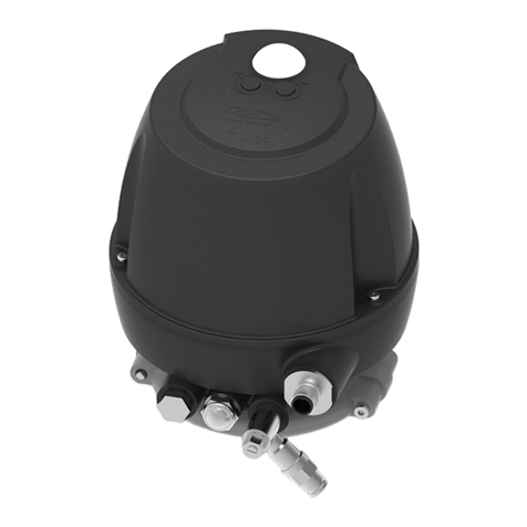
GEA T.VIS M-20 FDD User manual

Control and feedback systems
GEA T.VIS® M-20 FDD
Operating instruction (Translation from the original language)
430BAL014475EN_2

COPYRIGHT
These Operating Instructions are the English translation of the original operating
instructions in the sense of the EU Machinery Directive. This document is
protected by copyright. All rights reserved. The document may not, in whole or in
part, be copied, reproduced, translated or reduced to an electronic medium of
machine-readable form without the express permission of GEA Tuchenhagen
GmbH.
LEGAL NOTICE
Word marks
The designations T.VIS®, VARIVENT®, ECOVENT®, STERICOM®, VESTA® und
LEFF® are protected trademarks of GEA Tuchenhagen GmbH.
430BAL014475EN_2
2 03.09.2021

TABLE OF CONTENTS
1 General Information 5
1.1 Information on the Document 5
1.1.1 Binding Character of These Operating Instructions 5
1.1.2 Notes on the Illustrations 5
1.1.3 Symbols and Highlighting 5
1.2 Manufacturer address 6
1.3 Contact 6
1.4 EU Declaration of Conformity 7
1.5 Translated copy of the EU Declaration of Conformity 8
2 Safety 9
2.1 Intended use 9
2.1.1 Requirements for operation 9
2.1.2 Improper operating conditions 9
2.2 Operator’s Duty of Care 10
2.3 Subsequent changes 10
2.4 IP Protection classes 11
2.5 General safety instructions and dangers 11
2.5.1 Principles for safe operation 12
2.5.2 Environmental Protection 12
2.5.3 Electrical Equipment 12
2.6 Supplementary Regulations 13
2.7 Qualification of personnel 13
2.8 Safety equipment 14
2.8.1 Signs 14
2.9 Residual dangers 15
2.9.1 Electrostatically Endangered Components and Modules 15
2.10 Danger zones 16
3 Description 17
3.1 Design 17
3.2 Functional description 19
3.2.1 Operation Principle 19
3.2.2 Control top without solenoid valves 19
3.2.3 Control Top with Solenoid Valves 19
3.2.4 Control Top with Cap 20
3.2.5 Safety Air Exhaust/Installation Position 20
3.2.6 Reset function 21
4 Transport and storage 22
4.1 Storage conditions 22
4.2 Transport 22
4.2.1 Scope of supply 22
5 Technical data 23
5.1 Type plate 23
5.2 Technical data 24
5.3 Specification sensor module 24V DC Version 25
5.4 Switching point tolerances and signal output 26
5.4.1 Signal output 26
5.4.2 Signal output inverted 26
5.5 Lubricants 26
5.6 Equipment 27
6 Assembly and installation 28
6.1 Safety instructions 28
6.2 Establishing hose connections 28
6.3 Pneumatic connections 28
6.3.1 Control Top with 1 Solenoid Valve or Without Solenoid Valve 29
6.4 Electrical connections 29
6.4.1 Electrical 24V DC Wiring 30
6.5 Visual Display 31
6.5.1 Illuminated dome 31
6.5.2 Colour Changeover 32
6.6 Control Top Fitted to VARIVENT Valve FDD 32
430BAL014475EN_2
03.09.2021 3

6.6.1 Replacing Control Tops 33
7 Start-up 34
7.1 Safety precautions 34
7.2 Commissioning – Control Top without Solenoid Valve 34
7.3 Commissioning - Control Top with Solenoid Valve 35
7.4 Service Function 37
8 Operation and control 38
8.1 Safety instructions 38
9 Cleaning 39
9.1 Cleaning 39
10 Maintenance 40
10.1 Safety precautions 40
10.2 Inspections 41
10.3 Maintenance intervals 42
10.4 Tool 42
10.5 Removing the Control Top from the Valve 43
10.6 Dismantling the Control Top into its Components 43
10.6.1 Variants of the Control Top 43
10.6.2 Removing the Cap 43
10.6.3 Removing the Solenoid Valve or the Valve Plate 44
10.6.4 Removing the sensor module 46
10.6.5 Removing the pneumatic block 47
10.6.6 Fitting the Pneumatic Block 47
10.6.7 Install pneumatic connections 48
10.6.8 Mounting hood 49
10.7 Maintenance 49
10.7.1 Replacing the Seals on the Base 49
11 Alarms 51
11.1 Malfunctions and remedies 51
12 Decommissioning 52
12.1 Safety precautions 52
12.2 Disposal 52
12.2.1 General notes 52
13 Spare parts list - control top T.VIS M-20 FDD 53
14 Appendix 55
14.1 Lists 55
14.1.1 Abbreviations and terms 55
430BAL014475EN_2
4 03.09.2021

1 General Information
1.1 Information on the Document
The present Operating Instructions are part of the user information for the
product. The Operating Instructions contain all the information you need to
transport, install, commission, operate and carry out maintenance for the product.
1.1.1 Binding Character of These Operating Instructions
These Operating Instructions contain the manufacturer's instructions to the
operator of the product and to all persons who work on or use the product
regarding the procedures to follow.
Carefully read these Operating Instructions before starting any work on or using
the product. Your personal safety and the safety of the product can only be
ensured if you act as described in the Operating Instructions.
Store the Operating Instructions in such a way that they are accessible to the
operator and the operating staff during the entire life cycle of the product. When
the location is changed or the product is sold make sure you also provide the
Operating Instructions.
1.1.2 Notes on the Illustrations
The illustrations in these Operating Instructions show the product in a simplified
form. The actual design of the product can differ from the illustration. For detailed
views and dimensions of the product please refer to the design documents.
1.1.3 Symbols and Highlighting
In these Operating Instructions, important information is highlighted by symbols
or special formatting. The following examples illustrate the most important types
of highlighting.
Danger
Warning: Fatal Injuries
Failure to observe the warning can result in serious damage to health, or
even death.
► The arrow identifies a precautionary measure you have to take to avoid
the hazard.
Warning: Explosions
Failure to observe the warning can result in severe explosions.
► The arrow identifies a precautionary measure you have to take to avoid
the hazard.
General Information
Information on the Document
430BAL014475EN_2
03.09.2021 5

Warning!
Warning: Serious Injuries
Failure to observe the warning can result in serious damage to health.
► The arrow identifies a precautionary measure you have to take to avoid
the hazard.
Caution!
Warning: Injuries
Failure to observe the warning can result in minor or moderate damage to
health.
► The arrow identifies a precautionary measure you have to take to avoid
the hazard.
Notice
Warning: Damage to Property
Failure to observe the warning can result in serious damage to the
component or in the vicinity of the component.
► The arrow identifies a precautionary measure you have to take to avoid
the hazard.
Carry out the following steps: = Start of a set of instructions.
1. First step in a sequence of operations.
2. Second step in a sequence of operations.
®Result of the previous operation.
®The operation is complete, the goal has been achieved.
Hint!
Further useful information.
1.2 Manufacturer address
GEA Tuchenhagen GmbH
Am Industriepark 2-10
21514 Büchen
1.3 Contact
Tel.:+49 4155 49-0
Fax:+49 4155 49-2035
www.gea.com
General Information
Manufacturer address
430BAL014475EN_2
6 03.09.2021

1.4 EU Declaration of Conformity
GEA CONFIDENTIAL
EU Declaration of Conformity
Manufacturer:
GEA Tuchenhagen GmbH
Am Industriepark 2-10
21514 Büchen, Germany
We hereby declare that the devices named below
Model:
Control Top T.VIS M-20
Type:
24 VDC
AS-i
due to their design and construction as well as in the versions sold by us, meet the basic safety and health requirements of
the following guideline:
Relevant EC directives:
2014/30/EU
2011/65/EU
EMC
RoHS
Applicable harmonized standards, in
particular:
Other applied standards
and technical specifications:
EN IEC 61000-6-2: 2019
DIN EN 61000-6-4: 2011-09
DIN EN 61326-1:2013#
EN 62026-2: 2013
Remarks:
•The above mentioned standards have been taken into account in accordance with
the respective scope of application
Person authorised for compilation and handover of technical
documentation:
GEA Tuchenhagen GmbH
CE Documentation Officer
Am Industriepark 2-10
21514 Büchen, Germany
Büchen, 26 August 2021
________________________________
Matthias Südel
________________________________
Franz Bürmann
Managing Director
Head of Engineering
General Information
EU Declaration of Conformity
430BAL014475EN_2
03.09.2021 7

1.5 Translated copy of the EU Declaration of Conformity
Manufacturer: GEA Tuchenhagen GmbH
Am Industriepark 2-10
21514 Buchen, Germany
We hereby declare that the devices named below
Model: Control top T.VIS M-20
Type: 24 VDC
AS-i
due to their design and construction as well as in the versions sold by us, meet the basic safety and health requirements of the
following guideline:
Relevant EC directives: 2014/30/EU EMC
2011/65/EU RoHS
Applicable harmonized standards, in particular: EN IEC 61000-6-2: 2019
DIN EN 61000-6-4: 2011-09
DIN EN 61326-1:2013
Other applied standards and technical specifications: EN 62026-2: 2013
Remarks: •The standards stated have been taken into consideration according to the respective application area.
Person authorised for compilation and handover of technical
documentation:
GEA Tuchenhagen GmbH
CE Documentation Officer
Am Industriepark 2-10
21514 Büchen, Germany
Büchen,
Franz Bürmann
Managing Director i.V. Matthias Südel
Head of Engineering
General Information
Translated copy of the EU Declaration of Conformity
430BAL014475EN_2
8 03.09.2021

2 Safety
2.1 Intended use
The control top T.VIS M-20 FDD can be used for the pneumatic and electrical
connection of Tuchenhagen FDD process valves with VARIVENT adaptation.
Using the device for any other purpose is considered contrary to its designated
use.
The control top T.VIS M-20 FDD is available as
•without solenoid valve as position indicator
•with 1 solenoid valve as control top
The control top T.VIS M-20 FDD is completely installed on the dedicated
actuator/adapter of the process valve by means of a clamp connection. The
control top is able to feed air to the process valve externally through an air hose.
With T.VIS M-20 FDD the following can be carried out for all valves:
•monitoring the non-actuated position of the valve disk,
•monitoring the actuated position of the valve disk,
•coloured visualization of the valve position and status via the illuminated
dome fitted on the control top.
The control top T.VIS M-20 FDD may not be used in areas where an explosion
protection approval is required (e.g. ATEX, IECEx, CCCEx, HazLoc and other).
For a suitable control top with explosion protection approval (e.g. ATEX, IECEx,
CCCEx, HazLoc and other), please contact GEA Tuchenhagen at
Hint!
The manufacturer will not accept any liability for damage resulting
from any use of the valve which is not in accordance with the
designated use of the valve. The risk is borne solely by the operating
company.
2.1.1 Requirements for operation
The prerequisite for reliable and safe operation of the component is proper
transportation and storage as well as professional installation and assembly.
Operating the unit within the limits of its designated use also involves adhering to
the operating, inspection and maintenance instructions.
2.1.2 Improper operating conditions
The operational safety of the component can not be guaranteed under improper
operating conditions. Therefore avoid improper operating conditions.
The operation of the component is not permitted if:
•Persons or objects are in the danger zone.
•Safety devices are not working or were removed.
•Malfunctions have been detected on the component.
Safety
Intended use
430BAL014475EN_2
03.09.2021 9

•Damage to the component has been detected.
•Maintenance intervals have been exceeded.
2.2 Operator’s Duty of Care
The operating company of the component has a special responsibility for the
proper and safe handling of the component within their company. Only use the
component when it is in perfect operating condition in order to prevent danger to
persons and property.
This operating manual contains information that you and your employees need
for safe operation over the life of the component. Be sure to read these Operating
Instructions carefully and ensure that the measures described here are observed.
The operator's duty of care includes planning the necessary safety measures and
monitoring that these measures are observed. The following principles apply:
•Only qualified personnel may work on the component.
•The operating company must authorize personnel to carry out the relevant
tasks.
•Order and cleanliness must be maintained at the work stations and in the
entire area surrounding the component.
•Personnel must wear suitable work clothing and personal protective
equipment. As the operating company must ensure that work clothing and
personal protective equipment are used.
•Inform personnel regarding any properties of the product which might pose a
health risk and the preventative measures to be taken.
•Have a qualified first-aid representative on call during the operation. This
person must be able to initiate any necessary first-aid measures in case of an
emergency.
•Clearly define procedures, competences and responsibilities for those
working in the area of the component. Everybody must know what to do in
case of an emergency. Instruct the staff in this respect at regular intervals.
•The signs on the component must always be complete and easy to read.
Check, clean and replace the signs as necessary at regular intervals.
•Observe the Technical Data specified and the limits of use!
Hint!
Carry out regular checks. This way you can ensure that these
measures are actually observed.
2.3 Subsequent changes
No technical modifications should ever be made to this component. Otherwise
you will have to undergo a new conformity process in accordance with the EC
Machinery Directive on your own.
Safety
Operator’s Duty of Care
430BAL014475EN_2
10 03.09.2021

In general, only original spare parts supplied by GEA Tuchenhagen GmbH
should be fitted. This ensures that the component is always operating properly
and efficiently.
2.4 IP Protection classes
The control top T.VIS M-20 FDD in its standard version fulfils the requirements of
protection class IP66, IP 67 and IP69 (DIN EN 60529) and protection class
IP6k9k (ISO 20653).
IP classes provide information about the degree of protection an electrical device
housing provides against the ingress of solids (first digit) or humidity (second
digit). So-called IP codes are assigned to the protected systems. Its digits
represent common possible errors the system is protected from. The code always
starts with the letter IP for “international protection”.
First digit * Meaning
ISO 20653 DIN EN 60529 Protection against contact Protection against solids
6k 6 Complete contact protection Complete protection against dust
ingression (dustproof)
Second digit * Meaning
ISO 20653 DIN EN 60529 Protection against humidity
5 5 Protected against water jet (nozzle) from any angle
6 6 Protected against powerful water jets
6k Protected against powerful water jets under increased pressure
7 7 Protected against temporary immersion
9 Protected against high pressure spray downs
9k Protected against high pressure spray downs
* For additional digits and more detailed descriptions please refer to the pertinent standard.
Digits not to be mentioned can be replaced by the letter x (e. g. IPx6).
Concerning the ingress of humidity, IPx6 includes all lower IP classes. This is,
however, not the case for the higher protection class IPx7!
Hint!
The specified IP classes only apply if the connectors are connected
correctly, if the cable gland is properly sealed and if the control top is
fitted on the valve, see Chapter 6, Page 28.
2.5 General safety instructions and dangers
The component is safe to operate. It was built according to state-of-the-art
science and technology.
Nevertheless, dangers can arise from the component, if:
•the component is not used as intended
•the component is used improperly
•the component is operated under impermissible conditions
Safety
IP Protection classes
430BAL014475EN_2
03.09.2021 11

2.5.1 Principles for safe operation
Dangerous situations during operation can be avoided by safety-conscious and
proactive behaviour of the staff.
To ensure safe operation of the valve the following principles apply:
•The Operating Instructions must be kept ready to hand at the valve's place of
use. They must be complete and in clearly legible form.
•Only use the valve for its intended use.
•The valve must be functional and in good working order. Check the condition
of the valve before starting work and at regular intervals.
•Wear tight-fitting work clothing for all work on the valve.
•Ensure that nobody can get hurt on the parts of the valve.
•Immediately report any faults or noticeable changes on the valve to the
person responsible.
•Never touch the pipes and the valve when these components are hot! Avoid
opening the valve unless the process plants have been emptied and
depressurised.
•Observe the accident prevention regulations and all local regulations.
2.5.2 Environmental Protection
Harm to the environment can be avoided by safety-conscious and proactive
behaviour of the staff.
For environmental protection the following principles apply:
•Substances harmful to the environment must not be discharged into the
ground or the sewage system.
•Always observe the pertinent regulations relating to waste avoidance,
disposal and utilization.
•Substances harmful to the environment must be collected and stored in
suitable containers. Clearly mark the containers.
•Dispose of lubricants as hazardous waste.
2.5.3 Electrical Equipment
For all work on electrical equipment, the following principles apply:
•Access to electrical equipment should only be allowed to qualified
electricians. Always keep unattended switch cabinets locked.
•Modifications of the control system can affect the safe and reliable operation.
Modifications are only permitted with the express permission of the
manufacturer.
•After completion of all work, check that the protective devices are fully
functional.
Safety
General safety instructions and dangers
430BAL014475EN_2
12 03.09.2021

2.6 Supplementary Regulations
In addition to the instructions in this documentation the following also has to be
observed:
•pertinent accident prevention regulations,
•generally accepted safety rules,
•national regulations applicable in the country of use,
•work and safety instructions applicable in the facility,
•installation and operating regulations for use in potentially explosive areas.
2.7 Qualification of personnel
This section provides information on how the personnel working on the
component must be trained.
Operating and maintenance personnel must
•have the necessary qualification to carry out their tasks,
•be instructed with regard to possible dangers,
•know and observe the safety instructions given in the documentation.
Only allow qualified electricians to carry out work on the electrical equipment or
have a qualified electrician supervise the work.
Only allow specially trained personnel to carry out work on an explosion-
protected system. When working on explosion-protected equipment observe the
standards DIN EN 60079-14 for gases and DIN EN 50281-1-2 for dusts.
The following minimum qualifications are required:
•Training as a specialist for working independently on the component.
•Adequate instruction to work on the component under the supervision and
guidance of a trained specialist
Each employee must meet the following requirements to work on the component:
•Personal suitability for the respective task.
•Sufficient professional qualification for the respective task.
•Received instruction about the functionality of the component.
•Received instruction about operating sequences on the component.
•Familiar with the safety devices and their function.
•Familiar with these Operating Instructions, especially with the safety
instructions and the information which is relevant for the task on hand.
•Familiar with the basic regulations with regard to occupational health and
safety and accident prevention.
When working with the component, a distinction is made between the following
user groups:
Safety
Supplementary Regulations
430BAL014475EN_2
03.09.2021 13

User groups
Staff Qualifications
Operating personnel Adequate instruction and sound knowledge in the following areas:
•Functionality of the component
•Operating sequences on the pump
•What to do in case of an emergency
•Lines of authority and responsibilities with respect to the task
Maintenance personnel Appropriate training and a sound knowledge of the structure and
functionality of the component.
Sound knowledge in the following areas:
•Mechanical equipment
•Electrical equipment
•Pneumatic system
Authorization with regard to safety engineering standards to carry
out the following tasks:
•Setting devices into operation
•Earthing of devices
•Marking of devices
The relevant certificates of qualification must be submitted before
work can be carried out on ATEX certified machines.
2.8 Safety equipment
2.8.1 Signs
Dangerous points on the control top are indicated by warning signs, prohibition
signs and mandatory signs.
The signs and notes on the control top must always be legible. Any illegible signs
must be replaced immediately.
Safety
Safety equipment
430BAL014475EN_2
14 03.09.2021

Signs on the control top
Sign Meaning
Fig.1
General hazard warning
Fig.2
Warning Crushing
2.9 Residual dangers
Dangerous situations can be avoided by safety-conscious and proactive
behaviour of the personnel and by wearing personal protective equipment.
Residual dangers on the control top and measures
Danger Cause Measure
Danger to life Inadvertent switch-on of the
control top
Effectively disconnect all components, effectively prevent switch-
on.
Electric power Observe the following safety rules:
1. Isolate from the power supply.
2. Take appropriate measures to prevent switch on.
3. Test absence of voltage.
4. Earthing and short-circuiting.
5. Cover or safeguard any adjacent live parts.
Damage to property Welding can cause damage to
the electronics or result in data
loss.
Do not carry out any welding work in the vicinity of the control top
or make sure electronics are properly protected.
2.9.1 Electrostatically Endangered Components and Modules
The control top contains electronic components that are sensitive to electrostatic
discharge (ESD). Contact with electrostatically-charged persons or objects can
endanger these components. In the worst case they are destroyed immediately
or fail after being put into operation.
To minimize or prevent the possibility of damage resulting from sudden
electrostatic discharge,
•observe the requirements of DIN EN 61340-5-1 and 5-2,
•be careful not to touch the electronic components,
•also take care not to touch electronic components when supply voltage is
present.
Use ESD-compliant packaging when returning electronic components. (Contact
GEA Tuchenhagen if you have any questions.)
Safety
Residual dangers
430BAL014475EN_2
03.09.2021 15

2.10 Danger zones
Please observe the following notes:
•In the event of malfunctions, shut down the control top (disconnect from the
power and air supply) and secure it against being used.
•Before starting any service, maintenance or repair work, disconnect the
control top from the power supply and secure it against inadvertently being
switched back on again.
•Only allow a qualified electrician to carry out any work on the electrical power
supply.
•Check the electrical equipment of the control top at regular intervals.
Immediately remedy loose connections and molten cables.
•If work on live parts cannot be avoided, call in a second person, who can
operate the main switch in case of an emergency.
Safety
Danger zones
430BAL014475EN_2
16 03.09.2021

3 Description
3.1 Design
Fig.3
No. Designation No. Designation
7 Cap 43 Sensor module
8 Pneumatic block 50 Terminal strip unit
15 Clamp connection 63 Solenoid valves
24 Cable gland 64 Status light-emitting diode
The control top T.VIS M-20 FDD consists of:
•a 24 V DC sensor module for the detection of the two valve actuated
positions,
•a terminal strip unit for the switch-on type 24 V DC,
•a maximum of one solenoid valve for the actuation of the main stroke.
Description
Design
430BAL014475EN_2
03.09.2021 17

Sensor module structure
Printed circuit board switch-on type 24 VDC
Fig.4
1 DIP switch
2 J2
3 J1
4 Electronics
5 Measuring track
6 PV Y3
7 PV Y2
8 PV Y1
9 Reset
10 LED
Description
Design
430BAL014475EN_2
18 03.09.2021

3.2 Functional description
3.2.1 Operation Principle
The control top T.VIS M-20 FDD works with a microprocessor that contains the
software for operation, visualization and intelligent position detection.
The valve stroke is detected by a contactless position measuring system
integrated in the control top and the information is supplied to the
microprocessor.
Pneumatic and electronic components are located inside the control top. The
pneumatic components in this case are solenoid valves, the number of which
varies between 0 and 1, depending on the intended purpose. Control air is
supplied to the relevant control air chambers via air connections at the outside of
the control top. On the VARIVENT valve FDD, the main control air is supplied to
the actuator via a separate air connection on the control top through a hose.
The main task of the 24V DC sensor module with its integrated path measuring
system is to determine the valve position on the basis of the position of the valve
stem and to generate the corresponding feedback signals for this position in
order to send them to a higher-level control system.
Due to the illuminated dome integrated in the hood of the control top the light
emitting diodes arranged on the sensor module can be seen even if the hood is
closed. The light-emitting diode allows visualisation of the remaining functions of
the valve, see Section 6.5, Page 31.
3.2.2 Control top without solenoid valves
The control top T.VIS M-20 FDD without solenoid valves works as a position
indicator. During and after SETUP it indicates the status of the process valve
locally by a coloured LED under the illuminated dome so that it is visible over a
long distance.
The position feedback signals are supplied to the user by means of the following
communication method:
•24V DC PNP switching output
3.2.3 Control Top with Solenoid Valves
The control top with solenoid valves acts as a control top. The signalling takes
place in the same way as with the control top without solenoid valves. with the
difference being that the solenoid valve integrated in the base is operated in
accordance with the control signals.
The control signals are given by the user's process control system or by
operating the solenoid valves manually. To do this, use a screwdriver to turn the
screw (S) from 0 to 1, see figure.
Description
Functional description
430BAL014475EN_2
03.09.2021 19

Fig.5
3.2.4 Control Top with Cap
Fig.6: Control Top with Cap
The control top T.VIS M-20 FDD in its standard version fulfils the requirements of
protection class IP66, IP67 and IP69 (DIN EN 60529) and protection class IP6k9k
(ISO 20653).
3.2.5 Safety Air Exhaust/Installation Position
To provide protection against excess pressure which can build up in the inside of
the control top, a vent plug (E2) is fitted in the base.
In operating mode, the exhaust air from the lifting actuators is discharged via this
vent plug. In the unlikely event of a damaged solenoid valve or in case of sealing
problems, pressure relief is ensured.
Fig.7: Control Top with Cap
Description
Functional description
430BAL014475EN_2
20 03.09.2021
This manual suits for next models
1
Table of contents
Other GEA Control System manuals
Popular Control System manuals by other brands

HySecurity
HySecurity StrongArmPark DC 10 Programming and operations manual

Securakey
Securakey ENTRACOMP 26SA User & installation manual

Spraying Systems
Spraying Systems TeeJet TECHNOLOGIES BoomPilot installation manual

Foxtech
Foxtech GCU user manual

V-ZUG
V-ZUG Card-System 1 operating instructions

A/DA
A/DA PLATINUM II owner's manual

Aurora
Aurora Reax RXT Series quick start guide

Medha
Medha MAS 696 Operator's manual

Almot
Almot 08880892 Installation and use manual

Tether Tools
Tether Tools Case Air Wireless CAWTS03 product manual

Eaton
Eaton Greengate ControlKeeper 4 installation instructions

HEIDENHAIN
HEIDENHAIN AK LIC 413 operating instructions