Geca City CE408P User manual

E
N
IST-1408.PA01.02
File: IST-1408.PA01.02_CE408-EN (02.04.2014).docx
Dis.0534045
GAS CONTROL UNIT
CITY
CE408P
USER INSTRUCTIONS
GECA S.r.l
Via E. Fermi, 98 25064 Gussago (BS) Italy- Tel. (+39) 030 3730218 - Fax (+39) 030 3730228
http: www.cavagnaindustrie.com e-mail: info@gecasrl.it

IST-1408.PA01.02 - Dis.0534045 CE408P / User Manual Pag. 2/41
GECA S.r.l. - Via E. Fermi, 98 25064 GUSSAGO (BS) - Tel. 030 3730218 - Fax 030 3730228
Please read and keep care of this manual and the manual of
installed sensors too.
All documentation relating to gas detection plant should be preserved, because it
contains the procedures to be used during the routines verification and / or during the
periodic calibration. We recommend that you always complete the Setup Memorandum
Tables in the last pages of this manual. This will facilitate any possible change to the
configuration and/or in case of additional sensors, and operations and maintenance service
INFORMATION AND WARNINGS OF USE
The CE408 is a control unit for gas alarm systems up to 8 independent detection points. The
simple installation and easy configuration via the buttons make the unit suitable for use in
many areas, both civil and industrial.
It should be noted that inappropriate use or lack of maintenance can affect the operation of the
device and thus preventing the proper activation of alarms with potential serious
consequences for the user.
GECA disclaims any responsibility if the product is misused, altered or not as planned or put in
work incorrectly. The choice and use of the product are the sole responsibility of the individual
operator.
The rules, laws, etc.. mentioned, are the ones valid on the date of issue. In any case, must be
observed all applicable national regulations in the country of use.
The information contained in this document is accurate, current, and are the result of
continuous research and development, the specifications of this product may be changed at
any time without notice.
The Central has a clock with the automatic DST change. In the absence of power
supply, the
clock works with the lithium battery (on the board in the cover), its life, in
normal operation is over 5 years.
If the lithium battery is exhausted and the central remained completely without power, at
startup, you will need to enter the correct date and time (see page 29) and then the battery must
be replaced soon with a new one.
NOTES FOR READING INSTRUCTION
CE408P Central control unit for 4 Gas Sensors, expandable to 8 with ES404, with no.5 relay
outputs, expandable to 9 with ES4014 and 1 Logic Input.
ES404 Expansion card with no.4 inputs (4-20mA) for gas sensors.
ES414 Expansion card with no.4 relay outputs.
SENSOR It is the name that, for simplicity, are indicated the various models of Remote Gas
Sensors, with current output 4 to 20mA, that can be connected to the CE408P.
FIRMWARE Program inserted into the microcontroller which controls CE408P functioning.
Symbol that indicates an important warning in the instructions.
Symbol indicates information or additional explanation in the instructions.
Documento / Document name: IST-1408.PA01.02_CE408-EN (02.04.2014).docx
Oggetto / Subject : CE408P / Wall monut Central Unit
Rev. Data / Date Da / By Note
0 02/04/2014 UT/AS&FG Document Edition

IST-1408.PA01.02 - Dis.0534045 CE408P / User Manual Pag. 3/41
GECA S.r.l. - Via E. Fermi, 98 25064 GUSSAGO (BS) - Tel. 030 3730218 - Fax 030 3730228
SOMMARIO
DESCRIPTION.................................................................................................................. 4
Fig.1 - CE408P.....................................................................................................................................1
CE408P INSTALLATION.................................................................................................. 6
ELECTRICAL CONNECTIONS ........................................................................................ 6
Fig 2 – CE408P Dimensions and Template for wall mounting.................................................................1
The cover opens by unscrewing the 4 Allen screws ...............................................................................1
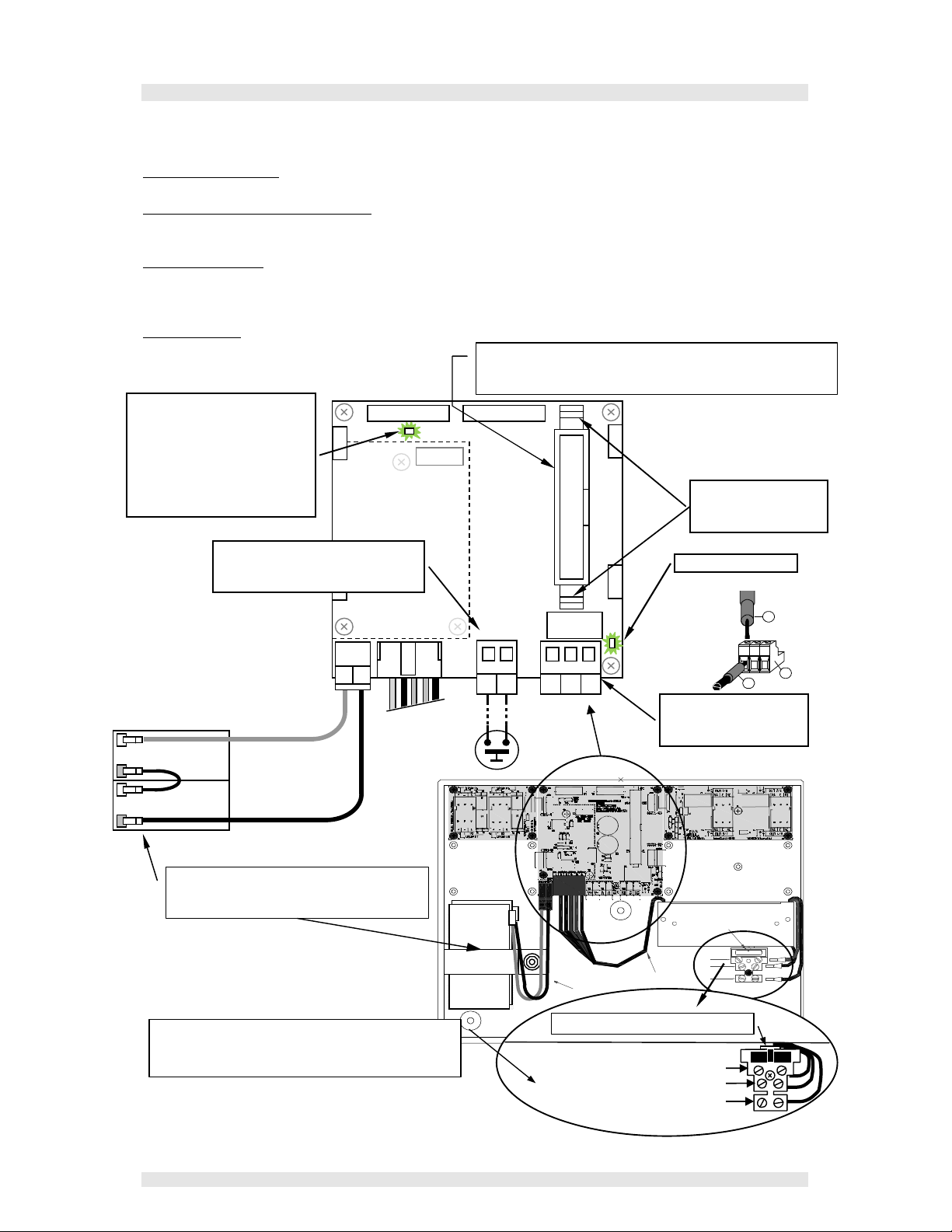
POWER CONNECTION .............................................................................................................7
Fig 3 – Wiring diagram for Power, Batteries, AUX input and output 9......................................................1
CoNNECTION WITH GAS SENSORS........................................................................................8
Fig 4 – Wiring diagram for Inputs Sensor 4 to 20mA and relay Outputs................................................... 1
UNIT’S OPERATION ........................................................................................................ 9
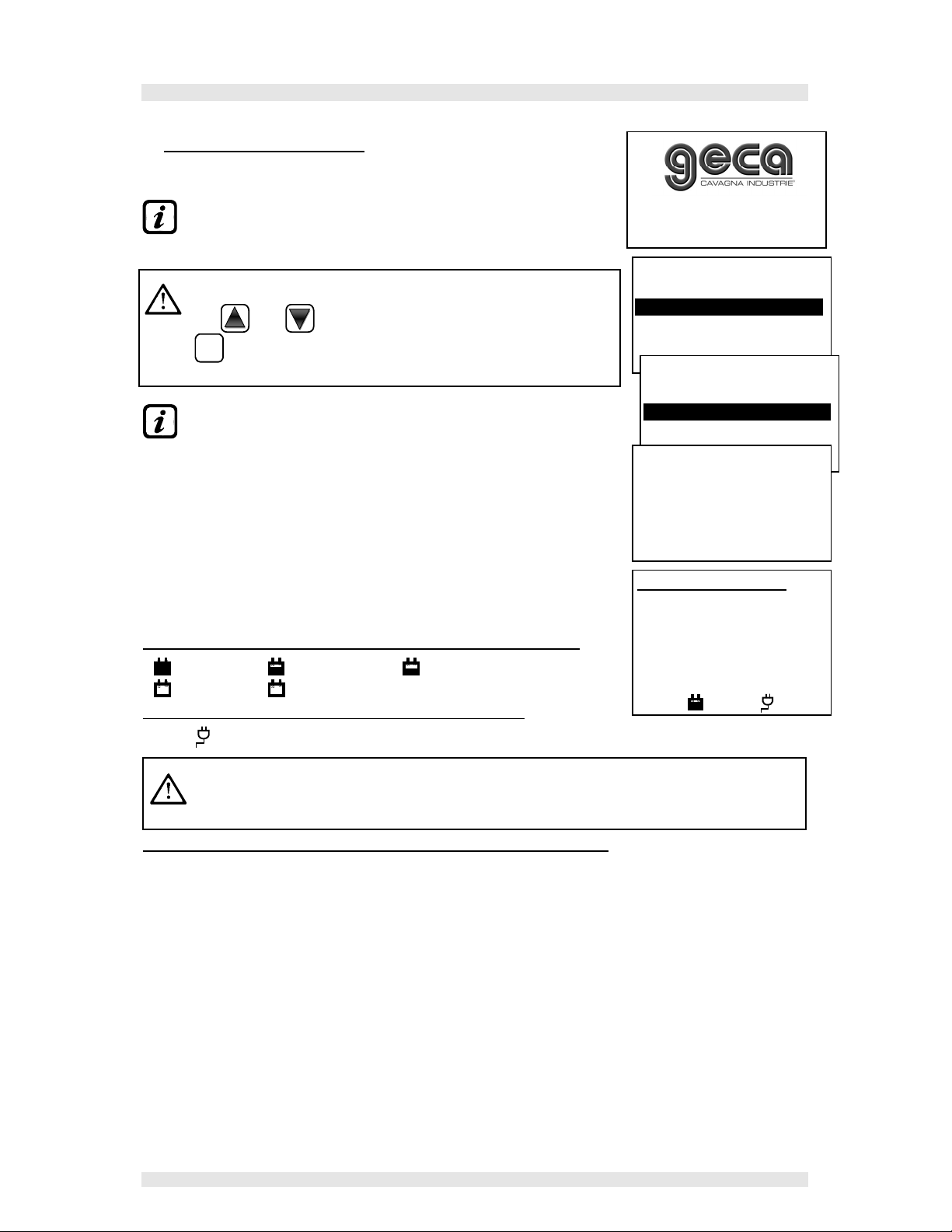
Fig 5 – CE408P Keyboard.....................................................................................................................1
MAIN MENU ................................................................................................................... 13
RESET ............................................................................................................................ 13
SENSORS....................................................................................................................... 15
ENABLE/DISABLE (Level 1) ............................................................................................................... 15
CONFIGURE (Level 2)........................................................................................................................ 17
COPY (Level 2) .................................................................................................................................. 21
DELETE (Level 2)............................................................................................................................... 22
MODIFY (Level 2)............................................................................................................................... 23
DETAILS ............................................................................................................................................ 23
LOGIC INPUT ................................................................................................................. 23
ENABLE/DISABLE (Level 1) ............................................................................................................... 23
CONFIGURE (Level 2)........................................................................................................................ 24
DELATE (Level 2)............................................................................................................................... 25
MODIFY (Level 2)............................................................................................................................... 25
DETAILS ............................................................................................................................................ 25
ZONES............................................................................................................................ 25
ENABLE/DISABLE (Level 1) ............................................................................................................... 25
CONFIGURE (Level 2)........................................................................................................................ 26
DELETE (Level 2)............................................................................................................................... 27
MODIFY (Level 2)............................................................................................................................... 28
DETAILS ............................................................................................................................................ 28
EVENTS.......................................................................................................................... 28
ALARMS/FAULTS .............................................................................................................................. 28
ALL .................................................................................................................................................... 29
SETTINGS ...................................................................................................................... 29
LANGUAGE (Level 1) ......................................................................................................................... 29
GENERALS........................................................................................................................................ 29
BUZZER (Level 1) .............................................................................................................................. 30
DATE and TIME (Level 1) ................................................................................................................... 30
ACCESS MENU.............................................................................................................. 30
EN./DIS. LEV.1/2/3 ............................................................................................................................. 30
MOD. PAS. LEV.1/2/3......................................................................................................................... 31
SERVICE ........................................................................................................................ 32
ELECTRIC TEST (Level 2) ................................................................................................................. 32
BATTERY (Level 2) ............................................................................................................................ 32
SENSORS STATE (Level 2) ............................................................................................................... 33
START-UP (Level 3)........................................................................................................................... 33
SD CARD........................................................................................................................................... 33
UPDATE FIRMWA. (Level 2) .............................................................................................................. 33
Fig.6- Board into housing cover.............................................................................................................1
APPENDIX...................................................................................................................... 35
CE408 Technical Specifications ............................................................................................35
TABLE with summary of Fault and Alarm messages. ..........................................................35
TABLE 1– List of GAS Sensors PRECONFIGURED ..............................................................36
TABLE 2 – PRECONFIGURED values for TLV.......................................................................37
TABLE 3 – PRECONFIGURED values for use with PARKING-EN (EN50545-1)....................37
TABLE 3 - Relays operation's PRECONFIGURED parameters. ............................................38
SETUP MEMORANDUM OF TABLES .....................................................................................39

IST-1408.PA01.02 - Dis.0534045 CE408P / User Manual Pag. 4/41
GECA S.r.l. - Via E. Fermi, 98 25064 GUSSAGO (BS) - Tel. 030 3730218 - Fax 030 3730228
DESCRIPTION
•The CE408P Gas Control Unit are wall mount housing 280x230x145 mm:
•The CE408P can be connected to all of our Gas Detectors (Sensors):
The CE408 can control up to 4 or 8 remote gas sensors.
- Three-Wire, 4÷20mA linear output models with “Replaceable Cartridge Sensor” for:
Flammable gases with Catalytic sensor TS292K(IP65) or TS293K(Ex”d”) series with 0÷20%LEL range.
Flammable gases with Pellistor sensor TS292P(IP65) or TS293P (Ex”d”) series with 0÷100%LEL range.
Flammable gases with Infrared sensor TS293I(Ex”d”) series with 0÷100%LEL range.
Toxic gases with electrochemical cell TS220E (IP65) or TS293E (Ex”d”) series.
Carbon dioxide with Infrared sensor TS220IC2 (IP65) or TS293IC2 (Ex”d”) series.
Oxygen with electrochemical cell TS220EO or TS293EO (Ex”d”) series with 0÷25%O2range.
With dual sensor for Parking TS255CB or TS255CN2
- Should be connecting all models without the replaceable Cartridge:
Flammable gases with Catalytic sensor ST441 (IP65) or SE193K (Ex”d”) series.
Carbon dioxide with Infrared sensor IR101 or IR102 series.
Should be connecting all models produced up to December 2008. Three-wire 4÷20mA linear
sensors for flammable gas or two-wire 4÷20mA linear sensors for toxic gases and oxygen.
Inputs are configurable for 4÷20mA sensors with referred current to ground and operating
characteristics same as our products (unit in %LEL or ppm, minimum operating voltage,
absorption, load resistance etc.).
We accept no liability for any malfunction, failure or damage caused by products not
compatible or not we produce.
•Each Sensor may be associated with a ZONE:
The sensors can be grouped into Zones (Max 2), which can associate up to 2 relay outputs
different for each alarm level and a FAULT.
•Each ZONE can be set according to operating LOGIC:
The logic used are the typical logic functions (AND, OR), management of adjacent sensors
(CORR.CON, CIRC.CON). Note that PARK-ITA is a function only for Italy (Italian Ministerial
Decree 01/02/1986).
•Each INPUT (Sensor) is self-protected and has a FAULT signal:
All sensors inputs are protected against short-circuit or wire breakings. If a short-circuit occurs,
the power supply to that input, is automatically stopped (all others continue to work properly). At
the same time, the FAULT signal is activated.
Mains Supply 90÷264 Vac
Battery (optional)
Fig.1 - CE408P
Wall mount housing
SD-CARD
4 or 8 Sensors
5 or 9 Relay Outputs
n.1 Logic Input

IST-1408.PA01.02 - Dis.0534045 CE408P / User Manual Pag. 5/41
GECA S.r.l. - Via E. Fermi, 98 25064 GUSSAGO (BS) - Tel. 030 3730218 - Fax 030 3730228
•Each Sensor can be configured in two ways:
Preconfigured Setup: Here you can choose one of the models of our production, (See list in Table
on page 35), which is then automatically set in the configuration recommended by the respective
thresholds and relay outputs. Is enough set the output number (relay) to complete the
configuration. The manual changes are, however, permitted.
General Configuration: Here you can configure any type of sensor (compatible or a new model
not yet listed), manually entering all parameters.
•The AUX input is configurable and can be associated with a relay output:
- Can be configured to activate one of the available relays and can be used by devices with NO or
NC contact outputs (gas sensors with a relay contact, smoke sensors, buttons, etc.).
•The CE408 can manage up to 5 or 9 Alarm relays:
Each sensor has three alarm levels (Threshold 1, Threshold 2 and Threshold 3) and a FAULT,
freely addressable to any relay output.
•The alarm thresholds can be configured with special mode of operation:
For use in car parking "PARKING EN" (EN 50545-1) or to the workplace, such as exposure limit
value TLV.
•Each output (relay) can be configured as follows:
- Silenceable: the output is disabled for the Silence time, when RESET is carried out and the
sensor is above the set threshold. This function can, for example, be used for the outputs
connected to audible warning devices.
- Silence Time: is the time, adjustable from 0 to 300 seconds, so Silenceable output (e.g. relay connected
to a siren) is disabled when the RESET is performed and a sensor is above the set threshold
- Hysteresis ON: is the delay, adjustable from 0 to 300 seconds, of the relay, associated with an alarm
threshold.
- Hysteresis OFF: is the delay, adjustable from 0 to 300 seconds, of the relay to return to normal
condition, when it ends the alarm.
- Time ON: is adjustable from 0 to 300 seconds. This function can only be used if you want to stop the
alarm output after a finite time, even if the sensor remains above the alarm threshold set (This
function cannot be used in conjunction with Hysteresis OFF delay). For example you can use it
to enable devices that cannot be powered down, or to send a pulse to a phone dialer.
- Memorized: the relay remains in alarm, even if the sensor returns below the threshold (this
function does not work if the Time ON or into Hysteresis OFF has already been inserted a value
other than zero), to return to normal conditions must be done RESET. Serves, for example, to
prevent the accidental or unauthorized resetting of a block valve of the gas, without first checking
the cause of the alarm.
-Positive Logic: the operation of the relay can be set normally activated or in positive logic,
therefore, if the relay fails, or is completely out of power, automatically moves into the Alarm
position, the NC contact becomes NO.
•The CE408 have a BUZZER inside:
The internal Buzzer sounds a Beep every touch of the keyboard. It can also be set to sound in
case of Fault and / or Alarm.
•The CE408 can store the Events:
The system can store up to 100 events comprising Alarms, Faults, Power ON, Mains blackout and
Resetting, that can be re-called at any time.
•The CE408 has an SD CARD slot:
It can be used for future updates of the central unit firmware.
•The CE408 is protected by 3 LEVELS of PASSWORD:
The functions of the control panel are accessible up to three password levels, with a code
composed of 4 numbers. The levels are for access to functions, used by the respective authorized
persons.
LEVEL 1: User / User
LEVEL 2: The Installer / Maintenance technician
LEVEL 3: Manufacturer / the assistance technician.

IST-1408.PA01.02 - Dis.0534045 CE408P / User Manual Pag. 6/41
GECA S.r.l. - Via E. Fermi, 98 25064 GUSSAGO (BS) - Tel. 030 3730218 - Fax 030 3730228
THE FOLLOWING INSTRUCTIONS DESCRIBES ALL THE CENTRAL SYSTEM
SETUP PROCEDURES AS WELL AS THE INSTALLATION PROCEDURES TO
BE EXECUTED ONLY BY AUTHORISED AND EXPERIENCED PERSONNEL.
CE408P INSTALLATION
The CE408P should be mounted on the wall using 3 screws and wall plugs (Ø 6 mm) or 3 M4 screws
and nuts, if the wall is not in masonry. The housing's base must be fixed through the 3 holes, one in
the center and the other in the bottom corners (Fig.2). The electrical connections should be executed
all on the housing base.
Inside the housing, it can also accommodate two 12V/1.3Ah Lead batteries connected in series (Fig.3) to
assure the system powering in case of mains blackout. The battery life is about 30 minutes with 8
sensors. (The batteries are not included in the delivery, but are available on request).
If required, to increase the autonomy (1 hour), it can be used two 7Ah batteries connected in
series, but causes the greatest dimension, shall be installed in a case outside the CE408P.
ELECTRICAL CONNECTIONS
The electrical connections should be executed all on the housing base.
To simplify installation, the housing cover may be detached from the base, by disconnecting the flat
cable, press on the two tabs on each side as shown in Fig. 3. To reconnect, simply push the flat cable
into the connector respecting the polarization, the two locking levers will close automatically.
The details of the connections to the mains, the two batteries, the AUX input and relay output
R9 are illustrated in Figure 3. While the details of the connections to the sensors and the other
outputs are illustrated in Figure 4.
The terminals are of "polarized inlet" type (1). We suggest to use lugs adequate to the
conductors (2) and to fix the wires to the box structure to avoid excessive stress to the circuits
and to the terminals. Use a screwdriver (3) of the right dimensions.
93mm
Fig 2 – CE408P Dimensions and Template for wall mounting
The cover opens by unscrewing the 4 Allen screws
229 mm
n 3 holes Ø 5mm
2.5

IST-1408.PA01.02 - Dis.0534045 CE408P / User Manual Pag. 7/41
GECA S.r.l. - Via E. Fermi, 98 25064 GUSSAGO (BS) - Tel. 030 3730218 - Fax 030 3730228
P WER C NNECTI N
Mains Power Supply (90÷264Vdc / 47÷63Hz) should be connected to terminal L, N and Earth at the
bottom of the housing base. The terminal has a protective fuse (5x20) 2A.
The two 12V/1.3Ah Lead batteries if required should be connected in series to BAT+ (Red) and BAT-
(Black) terminals. For the series connection, use the black cable supplied with two terminals (4mm
Fastens).
The auxiliary input (AUX) can be used to connect devices with a NO or NC contact (gas sensors with
relay contacts, smoke sensors, buttons, etc.). It can be configured to activate one of the available
relays. It can be connected to multiple devices if it’s are homogeneous. (If the device has an NC
contact must be connected in series or in parallel if its have all a contact NO).
Output Relay 9 has the same characteristics and use of those described on the next page.
Nero / Black / Noir
+
-
+
-
Rosso / Red / Rouge
AL120 (AC/DC 27,6V-60W )
L
T
N
(F)
(C)
(B)
(D)
(E)
(A)
(FUSE 2A)
B
B+
B
-
NC
C N
A A
Morsetto Ingresso Ausiliario AUX
Auxiliary Input Terminal AUX
Bornier entrée Auxiliaire AUX
n.2 Batterie 12V / 1,3Ah collegate in serie.
n.2 Batterie 12 / 1.3Ah Connected in Series
n.2 Battery 12V / 1,3Ah Raccor ées en série
Connettore Cavo Piatto per collegamento Coperchio
Flat-cable connector for cover connection
Connecteur câble plat pour raccor ement couvercle Connettore
Uscita Relè 9
Relay 9 output terminal
Bornes Sortie 9
Led: Batt TEST N
Si accen e urante la verifica i
funzionamento elle Batterie
(solo se installate) The LED
lights up when checking
functioning of batteries (if
installed).
Led:
UT 9 = N
Premere per Aprire
Press to Open
Appuyez pour ouvrir
Fig 3 – Wiring diagram for Power,
Batteries, AUX input and output 9.
3
1
2
Morsetto ad
innesto
polarizzato
Neutro /Neutral / Neutre
Terra / Herth /Terre
Linea / Line /Phase
Fusibile / Fuse / Fusible (5x20) 2A
Morsetto Alimentazione 90÷ 264 Vac / 47÷63Hz
90÷ 264 ac / 47÷63Hz Mains power supply terminal
Bornier Alimentation secteur 90÷ 264 Vac / 47÷63Hz

IST-1408.PA01.02 - Dis.0534045 CE408P / User Manual Pag. 8/41
GECA S.r.l. - Via E. Fermi, 98 25064 GUSSAGO (BS) - Tel. 030 3730218 - Fax 030 3730228
CONNECTION WITH GAS SENSORS
Please see the specifics User’s Manuals of the gas sensors.
Please note, that the CE408 has a board with 4 inputs and a board with 4 outputs. In Central
can be installed, a board ES404 and ES414 to have a total of 8 inputs and 9 outputs. The
diagrams, for simplicity, show all the 8 sensors and all relays outputs.
Sensors connection, with three-wire 4÷20mA transmitters, should be performed on the inputs board,
mounted in the base, on the left. The input terminals, “+, - and “S” should be connected to the
corresponding terminals of the sensor.
The connection wire section between the CE408 and the
sensors should be suitable to the distance, as shown in the
table. The connection needs a shielded cable. Shield
should be connected only to the central unit side, and on an
only point of EARTH that has to be equipotential.
The outputs connection, (Relays) should be performed on
the outputs board, mounted in the base, on the right. The relay output 9 is located on the central
board, see Figure 3. The nominal load of relay is 250 VAC - 2 A or 30 VDC – 2 A (resistive load).
The relay have changeover free voltage contacts, on the boards, indications NA means NO (Normally
Open), NC (Normally Close ), C(Common), refer to the relays in the normal position (not powered). If an
output is configured as POSITIVE LOGIC, the NO contact will become NC and NC will become NA.
Distance Cable
Max 200 meters 3 x1 mm2 shielded
Max 400 metri 3 x 1.5 mm2 shielded
Max 600 metri 3 X 2.5 mm2 shielded
Morsetto ad
innesto
polarizzato
3
1
2
+
S
-
+
S
-
+
S
-
+
S
-
S1
+
S
-
S3
+
S
-
S4
+
S
-
S2
+
S
-
Scheda ingressi 1÷4
Input boar 1÷4
Carte avec entrées 1÷4.
Scheda Uscite Relè 1÷4
Outputs boar with relays 1÷4
Carte avec relais 1÷4
ES404 Scheda Espansione ingressi 5÷8
Expansion boar with inputs 5÷8
Carte 'extension avec entrées 5÷8
N
C
NC
N
C
NC
N
C
NC
N
C
NC
Uscita Relè 1
1 output terminal
Bornes Sortie 1
Uscita Relè 3
3 output terminal
Bornes Sortie 3
Uscita Relè 2
2 output terminal
Bornes Sortie 2
Uscita Relè 4
4 output terminal
Bornes Sortie 4
+
S
-
+
S
-
+
S
-
+
S
-
S5
+
S
-
S7
+
S
-
S8
+
S
-
S6
+
S
-
AL120 (AC/DC 27,6V-60W )
L
T
N
(F)
(C)
(B)
(D)
(E)
(A)
(FUSE 2A)
Led: N
Relè
9
-
Relay
9
-
Relais
9
edi / See / oir Fig.4
Fig 4 – Wiring diagram for Inputs
Sensor 4 to 20mA and relay Outputs
N
C
NC
N
C
NC
N
C
NC
N
C
NC
ES414 - Scheda Espansione 4 Relè 5÷8
Expansion boar with relays 5÷8
Carte ’extension avec relais 5÷8
Uscita Relè 5
5 output terminal
Bornes Sortie 5
Uscita Relè 7
7 output terminal
Bornes Sortie 7
Uscita Relè 6
6 output terminal
Bornes Sortie 6
Uscita Relè 8
8 output terminal
Bornes Sortie 8
Rilevatori di gas / Gas Sensors / Son es e gaz

IST-1408.PA01.02 - Dis.0534045 CE408P / User Manual Pag. 9/41
GECA S.r.l. - Via E. Fermi, 98 25064 GUSSAGO (BS) - Tel. 030 3730218 - Fax 030 3730228
UNIT’S OPERATION
•Keyboard:
RESET
Can only be used on the main screen, it is used to reset the latched outputs to normal
operation, but only if the Sensor or Zone or Input has returned from the alarm condition. If there
are active alarms, outputs configured as Silenceable (e.g. alarm) returns to normal operating
conditions only for the time of silencing by default.
and Scroll the display and the numeric digits up and down. Keeping the key pressed,
increases the values' speed scrolling. In the main screen changes to display the status of
sensors, inputs and configured zones
MEN
Ù
Call up the Main Menu from any screen.
ENTER
Confirm the inserted data and in the main screen allows you to select the detail’s sensors.
and Scroll through the pages (6 sensors at a time and 7 events at a time), and input fields.
Keeping the key pressed, increases the speed scrolling.
ESC
Cancel an operation and in the main screen is used to enter to Main Menu.
•LED INDICATIONS
The CE408P has 3 LEDs, which show the status of unit operation (see also Appendix).
•FAULT (Yellow LED) Flashing = Preheat (Start Unit) or Firmware
Update.
Fixed ON = Fault (Sensor) + Buzzer if enabled.
Short flashing = Output relay associated with a latched Fault.
Rapid flashing = Batteries Fault.
•ON (Green LED) Fixed ON = Operation with mains power.
Flashing = Operation with the batteries.
•ALARM (Red LED) Fixed ON = Alarm 3 is active (Sensor or Zone) +
Buzzer if enabled.
Flashing = Alarm 1 and / or 2 active (sensor or area or logic input).
Short flashing = alarm latched (indented) (sensor or area or logic input).
•Internal Buzzer Indications
The CE408 has an internal buzzer that emits a beep when a key is pressed. It can also be configured
to sound in the event of a fault and / or an alarm.
•Sound short (0.1s) is always active Confirms the pressing of a
key.
•Continuous sound if configured Fault (Sensor or Zone)
•Continuous sound if configured Alarm 3 is active (Sensor or
Zone)
Keyboard
Fig 5 – CE408P Keyboard
Display
LEDs

IST-1408.PA01.02 - Dis.0534045 CE408P / User Manual Pag. 10/41
GECA S.r.l. - Via E. Fermi, 98 25064 GUSSAGO (BS) - Tel. 030 3730218 - Fax 030 3730228
•Display – Initial Screens
The CE408P when powered, for 5 seconds shows the model name and
firmware version.-----------------------------------------------------------------------
This information shall be accessible also in the menu
Settings
General
Info.
For more information read the chapter Settings.
Only at first power (and only then) will be asked to
choose
your language and to indicate if the
battery is present. Use the
key
and
to scroll through the languages and pressing
the key
ENTER
to confirm the choice. ----------------------------------------------
From this screen, you cannot go out without being made a choice.
If necessary, these choices can be changed.
Please see forward Settings
General
and Service
Battery.
After starts a decreasing count of 60 seconds, the time required to boot
the central unit, and allow the sensor to stabilize (preheating time). ----
After the preheating time, appears the Main screen that the control unit
displays in normal operation. The date is shown in the top row, the first 6
sensors (with the measured concentration and its state) and in the last
line, the battery status of charge (if installed) and the presence of mains
power:-------------------------------------------------------------------------------------
Symbols used to indicate the status of the battery (if installed):
= Full charge = Half charge. = Low charge
= Discharge Flashing = Fault.
Symbols used to indicate the presence of mains power:
= mains operation (is absent, when the power is by the batteries).
If the control unit, had lost the date and time, due to a malfunction or discharge of
the clock
backup battery, screen will be displayed for entering updated values (however, will
assure
the normal unit operation). By changing these parameters, see below, the section
SETTINGS
DATE and TIME
The status of a sensor, which appears on the main screen, may be:
•“- - - -“ = Sensor not Configured.
•FAULT = input current is less
than 1mA.
•NORM. = Normal There is no gas and there are no active alarms. The text blinks when
relay output is latched (Sensor or Zone).
•AL.1 = Alarm 1. The first alarm
threshold has been exceeded.
•AL.2 = Alarm 2. The second alarm
threshold has been exceeded.
•AL.3 = Alarm 3. The third alarm
threshold has been exceeded.
•F.S. = Full Scale. Current > 24 mA. The gas concentration has exceeded the Sensor
range.
LINGUA
-
LANGUAGE
LANGUE
1 ITALIANO
2 ENGLISH
3 FRANÇAIS
PRESENCE
BATTERY
1 NO
2 YES
WAIT
60
12:00 fri 15/11/2013
1) 2% LEL NORM
2)10.2 ppm AL.1
3) 300 ppm AL.3
4) - - - -
5) - - - -
6) - - - -
¯ ¯ ¯ ¯ ¯ ¯ ¯ ¯ ¯ ¯ ¯ ¯ ¯ ¯ ¯ ¯ ¯ ¯
CE408
ver.
1.00

IST-1408.PA01.02 - Dis.0534045 CE408P / User Manual Pag. 11/41
GECA S.r.l. - Via E. Fermi, 98 25064 GUSSAGO (BS) - Tel. 030 3730218 - Fax 030 3730228
When a sensor, a logic input or a zone, activate a relay output, the main screen appears a brief
display of alarm status. This allows to check quickly, the total number of active relays and their relative
alarm level.

IST-1408.PA01.02 - Dis.0534045 CE408P / User Manual Pag. 12/41
GECA S.r.l. - Via E. Fermi, 98 25064 GUSSAGO (BS) - Tel. 030 3730218 - Fax 030 3730228
The details of the individual items is as follows:
•FAULT: Indicates the number of active relays, relative to
exceeding the threshold of a fault (current <1 mA or> 24 mA), of a
sensor or a group of sensors that belong to a zone.
•AL 1: Indicates the number of active relays, relating to exceeding
the threshold of alarm 1, of a sensor or a group of sensors that
belong to a zone.
•AL 2: Indicates the number of active relays, related to exceeding
the threshold of alarm 2, of a sensor or a group of sensors that
belong to a zone.
•AL 3: Indicates the number of active relays, relating to exceeding the alarm threshold 3, of a
sensor or a group of sensors that belong to a zone.
•INPUT. : Indicates the number of active relay, logic input.
The screen can be closed by pressing the
ESC
key or the
RESET
key. If a new alarm occurs the screen
will appear again utomatically.
From the Main screen, by pressing
and keys, to scroll through the sensors, in groups of 6
at a time. Pressing
ENTER
key highlights the sensor in the first row. While, using the keys
and
to scroll through the sensors (in the page) shown on the display.
Pressing the key
ENTER
again, you view the details of the highlighted
sensor, (of course only if it is configured). ---------------------------------------
Explanations of the details are as follows:
•1
st row shows the number of the sensor.
•2
nd row shows the name of the gas being measured.
•3rd row shows the currently
measured gas concentration, the unit of measure and current value (mA) (current generated by
the sensor).
•4th line indicates the Zone.
•the 6th line indicates the
output number (Relay), corresponding respectively to:
1st Threshold (AL1) 2nd Threshold (AL2) 3rd Threshold (AL3) FAULT.
Value 0(zero) indicates, at that threshold, the output not been assigned, while the highlighted value
indicates that output relay is currently active (alarm). The values are real time updated.
Pressing the
ESC
key it returns to the screen of the sensors. Then press again the
ESC
, to return to
the Main Screen.
Using the keys
and
is displayed, in cyclic mode, the situation of
the Zones (Z1 and Z2) and the Logic Input AUX (I1). ------------------------
Note that the model CE408P has only 2 Zone and 1 Logic Input.
The status of a logic input can only be ACTIVE or DEACTIVE, while a
Zone has the same status of a sensor, except for the full-scale. ----------
Press
ESC
to enter the Main Menu.
12:00 fri 15/11/2013
Z1) NORM.
Z2) - - - -
¯¯¯¯¯¯
¯¯¯¯¯¯¯
¯¯¯¯¯
12:00
fri
15/11/2013
¯ ¯ ¯ ¯ ¯ ¯ ¯ ¯ ¯ ¯ ¯ ¯ ¯ ¯ ¯ ¯ ¯ ¯
N.
1
GAS: METHANE
2%LEL 05.60mA
ZONE:0
OUTPUT:
0 1 29
12:00 frI 15/11/2013
I1) LOW DEACTIVE
¯ ¯ ¯ ¯
¯
¯ ¯ ¯ ¯ ¯
¯ ¯ ¯ ¯
12:00 fri 15/11/2013
¯ ¯ ¯ ¯ ¯ ¯ ¯ ¯ ¯ ¯ ¯ ¯ ¯ ¯ ¯ ¯ ¯ ¯
ALLARMS STATUS
FAULT: 00 AL 1: 01
AL 2 : 00 AL 3: 03
INPUT: 00
Press Reset/Esc

IST-1408.PA01.02 - Dis.0534045 CE408P / User Manual Pag. 13/41
GECA S.r.l. - Via E. Fermi, 98 25064 GUSSAGO (BS) - Tel. 030 3730218 - Fax 030 3730228
MAIN MENU
The CE408 is provided with a main menu from which you can manage all
of its functions.
The name of each line indicates the thematic area on which we can take
action, by accessing the corresponding submenus.---------------------------
Pressing the key
and
to scroll through the menus.
Press
ENTER
to enter the corresponding submenus.
Some submenus have an access level to enable it; you must enter the specific password.
If you try to enter a submenu without entering the password, the access
is denied. A higher access level also enables the lower one.---------------
The required access level is indicated, when necessary, to the left of the individual items of the
manual. To enable them, with the password, see the menu Access.
List and short description of the accessible menus:
RESET: Carries out a reset the control unit and return to the main menu.
SENSORS: Enter a submenu where you can enable, disable, configure, modify, copy, delete,
and view the details of the sensors.
INPUTS: Enter a submenu where you can enable, disable, configure, modify, copy, delete,
and view the details of the logic input.
ZONE: Enter a submenu where you can enable, disable, configure, modify, copy, delete,
and view the details of the zones.
EVENTS: Enter a submenu where you can view, all events or ones related only to faults /
alarms.
SETTINGS: Enter a submenu where you can change, the language, general settings, the
buzzer settings and the date and time.
ACCESS MENU: Enter a submenu where you can enable, disable, modify, the password, of the
relative access levels.
SERVICE: Enter a submenu where you can perform electrical testing of the control unit
manage the battery and display the status of the sensors.
SD CARD: Enter a submenu where you can update the Firmware of the control panel via an
SD Card
RESET
The RESET item in the main menu, performs the same function as the
RESET
key, reset the latched
outputs to normal operation, but only if the Sensor or Zone or Input has returned from the alarm
condition.
If there are active alarms, outputs configured as Silenceable (e.g. an
alarm) return to normal operating conditions only for the time of
silencing.
SENSORS
7 DETAILS
LEVEL NOT
ENABLED
ACCESS
DENIED
Press Esc
STOP
CE408
1 RESET
2 SENSORS
3 INPUTS
4 ZONES
5 EVENTS
6 SETTINGS
7 ACCESS
MEN
U’

IST-1408.PA01.02 - Dis.0534045 CE408P / User Manual Pag. 14/41
GECA S.r.l. - Via E. Fermi, 98 25064 GUSSAGO (BS) - Tel. 030 3730218 - Fax 030 3730228
When performing the RESET (with key or from the menu), the display
shows the confirm message for about 3 seconds, then the previous
screen reappears automatically. ---------------------------------------------------
12:00 fri 15/11/2013
RESET
PERFORMED

IST-1408.PA01.02 - Dis.0534045 CE408P / User Manual Pag. 15/41
GECA S.r.l. - Via E. Fermi, 98 25064 GUSSAGO (BS) - Tel. 030 3730218 - Fax 030 3730228
SENSORS
In this submenu you can manage the sensors connected to the unit.
Below, the individual items are described in detail, with the same level
password, which is indicated in parentheses.-----------------------------------
ENABLE/DISABLE (Level 1): These two items allow you to enable or
disable one or more sensors, even simultaneously.
The disabled sensors, no longer trigger the alarm and fault outputs, associated with them
(the outputs remain in a state of normal operation, and then the alarms associated with them
are not triggered).
Disabled status is displayed on the main screen, next to the sensor, with
asterisks “*****”.
To enable or disable a sensor press the
ENTER
key on the relevant item,
highlighted. With
and
it is possible to select, if you take action
on a single sensor or on a group of sensors. -----------------------------------
The first line, is acting on a single sensor. Pressing
ENTER
on the first line, will highlight the number of
the sensor. Then with
and
you choose the desired number and
pressing
ENTER
the confirmation window will appear.
The second line, acts on a group of sensors. -----------------------------------
Pressing
ENTER
on the second line, will highlight the first sensor’s number
of the group.
You can enable or disable all sensors, including between two,
both from the smallest to the largest number, and the reverse.
If the two numbers of sensors were equal, the effect is identical to the
management of a single sensor.
With
and
you can choose the number of required sensor,
pressing
and
you change from one value to another and then
pressing again
ENTER
confirmation window will appear.------------------------
Press
ENTER
to confirm. In case, you want to go back, press
ESC
. Each
time you press this key, you will return to the previous step.
If the sensor or one of the group’s sensors is not configured, a window
notifies you that the operation is not possible. ----------------------------------
ENABLE
SENSOR N.
FROM N. TO N.
ENABLE
SENSOR N.
FROM N. TO N.
ENABLE
CONF
I
RM ?
YES = ENTER
NO = ESC
ENABLE
SENSOR
N. 1
NOT CONF.
STOP
SENSOR
1 ENABLE
2 DISABLE
3 CONFIGURE
4 COPY
5 DELETE
6 MODIFY
7 DETAILS

IST-1408.PA01.02 - Dis.0534045 CE408P / User Manual Pag. 16/41
GECA S.r.l. - Via E. Fermi, 98 25064 GUSSAGO (BS) - Tel. 030 3730218 - Fax 030 3730228
Then the screen returns to the selection of the sensor.
If you have selected a group of sensors, the ones that have
been configured are enabled or disable. Dialog box appears to
warn you that you have selected one or more zones are not
configured.
If this procedure is correct, a window notifies you that the operation has
been successful. -----------------------------------------------------------------------
Then the screen returns to the beginning of the management for Enabled
or Disable.
ENABLE
SENSOR
N. 1
ENABLED

IST-1408.PA01.02 - Dis.0534045 CE408P / User Manual Pag. 17/41
GECA S.r.l. - Via E. Fermi, 98 25064 GUSSAGO (BS) - Tel. 030 3730218 - Fax 030 3730228
CONFIGURE (Level 2): There are two ways to configure a sensor.
The first allows you to choose between those preconfigured sensors,
the second allows a generic configuration. -----------------------------------
In the first case, you can configure only the models of our production (see
list in Table on Page 35), which have some parameters fixed (non-editable)
and other editable, all have already been set, including the configuration
of the outputs.
In the second case, you can manually enter all the parameters, which are
freely editable.
For safety, the outputs are configurable only when configuring or changing a sensor, a logic
input or a zone.
You cannot configure the outputs separately.
Configuring PRECONFIGURED SENSOR: To proceed with the
configuration, press
ENTER
on the relevant item highlighted.
Then, using
and
keys and pressing
ENTER
you can choose the
sensor’s number to be configured. ------------------------------------------------
To configure a dual sensor (TS255 series), you must use two
consecutive sensors (1-2, 2-3, 3-4, etc.); starting with the first of
the two. You cannot start from the sensor n. 8.
Then you can choose the model number.
The code of our products consists of 2 letters followed by 3 numbers,
and, if necessary, by other letters (2 to 4).---------------------------------------
To choose the desired one, is followed the same structure, must be
chosen before the first two letters, then 3 numbers and then the other
letters (if present).
With
and
you can scroll between the groups of letters and
numbers that make up the model, with
ENTER
you can confirm your choice
and move on. With
ESC
you can go back.
Example: for model TS292KM, first select TS and confirm by pressing
ENTER
. Then select the second item TS292 and confirm with
ENTER
key.
Finally complete the selection by selecting the complete entry TS292KM
and confirm with.
After choosing the model, its configuration is automatically loaded. ------
To scroll through the different items, use
and
keys. Pressing
ENTER
on the item, the value is highlighted to indicate that it is editable.
Use
and
to change the value, using
and
you change
from to another field in the same row (where applicable).
Then pressing
ENTER
the change will be accepted. Pressing
ESC
will restores the previous value and
the entire row is selected, indicating that you can only scroll through the items.
SENSORS CONFIG.
1 PRECONF. SENS.
2 GENERIC SENS.
PRECONF
IG
.
SENS.
SENSOR N. 1
PRECONFIG. SENS.
SENSOR N. 1
MODEL: IR
SE
TS
PRECONFIG. SENS.
SENSOR N. 1
MODEL: TS220
TS255
TS292
TS293
PRECONF
IG.
SENS.
SENSOR N. 1
MODEL: TS292KM
TAG:
TYPE: Flammable
GAS: METHANE
UoM: % LEL
PRECONF
IG. SENS.
SENSOR N. 1
MODEL: TS292KB
TS292KG
TS292KI
TS292KM

IST-1408.PA01.02 - Dis.0534045 CE408P / User Manual Pag. 18/41
GECA S.r.l. - Via E. Fermi, 98 25064 GUSSAGO (BS) - Tel. 030 3730218 - Fax 030 3730228
Description of items related to the Preconfigured sensor:
TAG: It is a TAG than 10 characters, selectable one at a time, where you can write a note or a
reminder for a sensor (e.g. FLOOR 2, BOILER, etc.).
AL.: Defines the type of ALARM of the sensor and establishes how they should be set the
thresholds of the various alarm levels. In the specific:
•INCREASING: The alarm levels will be set in ascending order, i.e. SENSOR
SCALE ≥ALARM 3 ≥ALARM 2 ≥ALARM 1 ≥FAULT (current <1mA). All our sensors, except
for the detection of oxygen, are set with this type of alarm.
•DECREASING: The alarm levels must be set in descending order, i.e. FAULT
(current <1mA) ≤ALARM 3 ≤ALARM 2 ≤ALARM 1 ≤SENSOR SCALE. Only our sensors to
detect oxygen are set with this type of alarm.
•OXYGEN: The alarm levels should be set to detect deficiency or excess of the
normal presence of oxygen in the air (20.9% v / v), i.e. FAULT (current <1mA) ≤ALARM 2 ≤
ALARM 1 ≤20.5% volume and 21.5% volume ≤ALARM 3 ≤SENSOR SCALE. Our sensors to
detect oxygen can be set with this type of alarm.
Alarm 2 is displayed as AL
,while the alarm 3 as AL
.
•TLV: (Threshold Limit Values) are the exposure limit values for toxic substances to
which workers may be exposed every day for the entire duration of working life without harmful
effects. Must be set in ascending, i.e. SENSOR SCALE ≥ALARM 3 ≥ALARM 1 ≥ALARM 2 ≥
FAULT (current <1 mA). In this case, each alarm level is a value obtained with a temporal
average. TLVs in detail are:
oALARM 1 = TLV-TWA (Time-Weighted Average)is
the time-weighted average concentration for a conventional 8-hour workday and a 40-hour
workweek, to which it is believed that nearly all workers may be repeatedly exposed, day after
day, without adverse effect. This alarm is triggered when the weighted average concentration
within 8 hours exceeds the set threshold.
oALARM 2 = TLV-STEL (Threshold Limit Value–
Short-Term Exposure Limit)is the concentration to which it is believed that workers can be exposed
continuously for a short period of time without suffering from irritation, chronic or irreversible
tissue damage, or narcosis. STEL is defined as a 15-minute TWA exposure, which should not
be exceeded at any time during a workday. This alarm is triggered when the weighted average
concentration in the last 15 minutes, exceeds the set threshold.
oALARM 3 = TLV-C (Threshold Limit Value-Ceiling)is
the concentration that should not be exceeded during any part of the working exposure. This
type of alarm is triggered when the instantaneous concentration exceeds the set threshold. Are
not carried out, time weighted average.
Only our sensors for detection of toxic gases can be set up with this type of alarm.
•PARKING EN:The alarm levels should be set so increasing, i.e. SENSOR
SCALE ≥ALARM 3 ≥ALARM 2 ≥ALARM 1 ≥FAULT (current <1 mA). In this case, the first
two levels of alarm representing a value obtained with a time average between 5 and 60 min.
(according to standard EN 50545-1 for the car parks). This value can be set via the parameter
TWA. Level 3, however is instantaneous.
This type of alarm (see Table 3) can only be set with our sensors for toxic gases in car parks car
(series TS220 and TS293 / EC/EN/EN2) or the dual sensors (series TS255).
•ZONE: Sets the area that will be associated with the sensor. The areas available are
2. The area 0means that the sensor is not associated in any area
•TWA: This parameter can only be changed in the sensors where the alarm is
PARKING EN (in all other cases is fixed at zero). Is how many minutes are carried out time-
weighted average for the activation of the 2 alarms? The value can be chosen between 5 and 60
min. (in accordance with standard EN50545-1 for the car parks).
•THRESHOLD: Indicates the value, above which, the corresponding alarm is
activated.
The thresholds have a hysteresis to prevent the output will cycle on and off continuously
(concentration fluctuates around the threshold value). This hysteresis is 20% of the value of the set
threshold, for all models of sensors. Only exception is for models for detection of oxygen

IST-1408.PA01.02 - Dis.0534045 CE408P / User Manual Pag. 19/41
GECA S.r.l. - Via E. Fermi, 98 25064 GUSSAGO (BS) - Tel. 030 3730218 - Fax 030 3730228
(TS220EO/TS293EO) whose hysteresis is 2%. The level of fault (FAULT) has a hysteresis of
1mA, so a sensor failure comes out when his current exceeds 2mA.

IST-1408.PA01.02 - Dis.0534045 CE408P / User Manual Pag. 20/41
GECA S.r.l. - Via E. Fermi, 98 25064 GUSSAGO (BS) - Tel. 030 3730218 - Fax 030 3730228
Description of the items relating to the outputs:
OUTPUT N.: Indicates the number of the output (relay). The configurable outputs ranging from 1-9.
The output of 0indicates that there is no output associated with that alarm level.
If the output boards are not properly connected or mounted, for safety, the
corresponding outputs cannot be configured.
•If the board ES414 is not connected to the terminal OUT 1-4 outputs will only be available
from 5 to 9.
•If the board ES414 is not connected to the terminal OUT 5-8 outputs will only be available
from 1 to 4 and 9.
•If it was not connected any board ES414, the only output available is 9.
•The outputs have to configure in a unique way. So, if you were choosing the same output for
different alarm levels will be considered valid, only the configuration of the higher alarm. You
cannot choose the same output for a level of alarm and fault
SILENCEABLE: Indicates that the output is disabled, the Silence time, when RESET is performed.
This function can be used for the outputs connected to audible warning devices
SILENCE T.: Indicates the Silence time (adjustable from 0 to 300 seconds), so Silenceable output
is cancelled by RESET.
DELAY ON: DELAY ON is the relay delay (Adjustable from 0 to 300 seconds) associated with an
alarm threshold.
If the alarm type was selected as PARKING EN and you were programming the output on the
threshold 3, this delay can only be set from 60 to 300 seconds.
DELAY OFF/TIME ON: The first item DELAY OFF (adjustable from 0 to 300 seconds), is the
relay’s delay, to return to normal status, when it ends the alarm condition. The second item,
TIME ON (adjustable from 0 to 300 seconds) can only be used to stop the alarm output after
a preset time, even if the sensor remains above the alarm threshold set. (It can be used to
activate devices that cannot be powered on or to send a pulse to a phone-dialer).
The two functions HISTER.OFF and TIME ON, cannot be used together, or with the SAVE
function. For safety, if the delay is set other than zero, the parameter stores will be
automatically changed to NO.
POS.LOGIC: Indicates that the output operation is in POSITIVE LOGIC or the relay is normally
activated, so, in case of failure automatically moves into the position of the alarm, and then
the NC contact becomes NO
LATCHED: Indicates that the relay remains in alarm, even if the sensor back below the alarm set.
To bring it back into the normal, RESET must be performer.
The function LATCHED, cannot be used simultaneously with DELAY OFF or TIME ON. For
safety, if the parameter LATCHED, was set YES, the parameters DELAY OFF and TIME ON,
will be automatically set to Zero
At the end of the screen is written SAVE to save the configuration entered. Pressing
ENTER
the
confirmation window will appear. Press again
ENTER
to confirm, or press
ESC
to go back and make
changes.
Only for double sensors, TS255 series, at the end of the screen, the message CONTINUE
appears. Because in this case, must be programmed two consecutive sensors. Only after the
second configuration, you can save the configuration entered.
If the set thresholds were in contrast with the criteria for this type of alarm
set, or if it had selected the same output for one of the alarm levels and
the Fault, a warning message will appear.---------------------------------------
Then the screen returns to the configuration of the sensor
PRECONF
IG
.
SENS.
ERROR
CONFIGURATION
CONTROL
PARAMETERS
Table of contents
Other Geca Control Unit manuals
Popular Control Unit manuals by other brands

Viega
Viega Easytop XL Series Instructions for use

Interlogix
Interlogix SuperBus 2000 PIV installation instructions

IKA
IKA WiCo RET control-visc operating instructions

Deep Sea Electronics Plc
Deep Sea Electronics Plc DSE7450 Operator's manual

DoorHan
DoorHan DCUH-1 manual

Digilent
Digilent PmodCLP Reference manual