GEMÜ Gebr. Müller Apparatebau GmbH & Co. KG · Fritz-Müller-Str. 6-8 · D-74653 Ingelngen-Criesbach
Phone +49(0)7940/123-0 · F
ax +49(0)7940/123-224 ·
[email protected] · www
.gemu-group.com
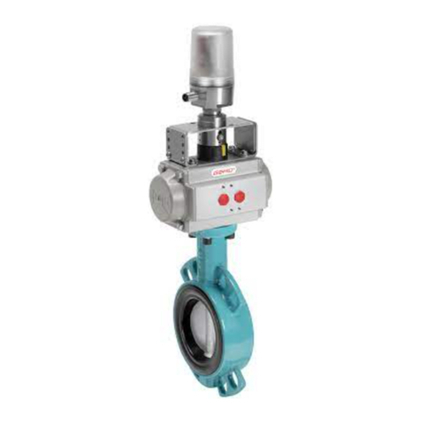
Instructions for converting the GEMÜ 488 from the J&J actuator to the GEMÜ 9468 actuator
Valid for version 488200W232A1NLR5 AEJ2300
Replacement of the J2 L300 AE F07/F10S22 actuator with the 9468000ZF10YS22C10E4200ABE4 actuator
WARNING
The equipment is subject to pressure!
▶ Risk of severe injury or death!
• Only work on depressurized plant.
WARNING
Corrosive chemicals!
▶ Risk of caustic burns!
• Wear appropriate protective gear when disas-
sembling.
CAUTION
Hot plant components!
▶ Risk of burns!
• Only work on plant that has cooled down.
1. Put on appropriate protective gear.
2. Switch o the electrical connection to the buttery valve
actuator.
3. Secure against recommissioning.
4. Depressurize the plant or plant component.
5. Provide a suitable collection container for possible leakages.
6. Ensure that the actuator is only replaced on valves that are not
used as end-of-line valves.
Disassembling the old (J2) actuator
The old actuator can be disassembled in any position.
• Switch o the power supply to the actuator and secure it
against recommissioning.
• Disconnect the plug for the power supply and the feedback
signal.
• Undo and remove the screws.
• Disassemble the actuator.
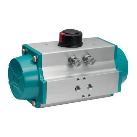
Preparing the new actuator (GEMÜ 9468)
The default state of the actuator is in the open position. The
position of the actuator must be adapted to t the position of the
buttery disc.
• Read the position of the buttery disc at groove a.
a
▶Groove a transverse to piping direction: Buttery valve closed.
▶Groove a in piping direction: Buttery valve open.
Check whether the position of the actuator is in correct
alignment with the position of the buttery disc.
open
auf
closed
zu
Changing the position of the new actuator
Crank handle
for manual
override
Blanking
cover for
manual
override
• Unscrew the blanking cover using a screw driver.
• Connect the crank handle.
• To move the actuator into the open position: Turn the crank
handle anticlockwise.
• To move the actuator into the closed position: Turn the crank
handle clockwise.
• Pull out the crank handle.
• Put the blanking cover back on.
Mounting the new actuator
• Place the actuator on the shaft connection.
• Check whether the holes of the ange connection are
correctly aligned and correct the position of the actuator via
the crank handle if necessary.
• Connect the actuator to the buttery valves with four screws.
• Tighten the screws to a tightening torque of 48 - 52 Nm.
Electrical connection
• Make sure that the electrical voltage complies with the
specications on the product label of the actuator.
• Connect the power supply to interface X1 (Power).
• Connect the feedback signal to interface X2 (Signal).
• Turn on the electrical connection.
Functional test
• Open and close the actuator.
• Make sure that the actuator opens and closes the buttery
valve correctly.
• Ensure that there are no leakages.
488
OPENCLOSE
OPENCLOSE
08/2015


