GEM 9428000ZG05YS08C1A01015 User manual

GEMÜ 9428
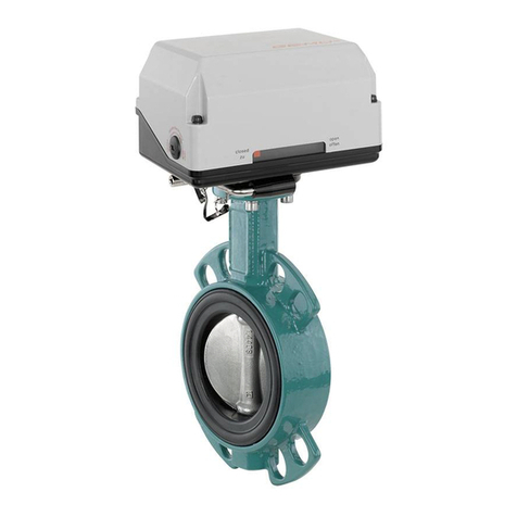
Motorized quarter turn actuator
Operating instructions
EN
further information
webcode: GW-9428

All rights including copyrights or industrial property rights are expressly reserved.
Keep the document for future reference.
© GEMÜ Gebr. Müller Apparatebau GmbH & Co. KG
31.05.2023
www.gemu-group.com2 / 34GEMÜ 9428

Contents
1 General information ............................................. 4
1.1 Information .................................................... 4
1.2 Symbols used ................................................ 4
1.3 Warning notes ............................................... 4
2 Safety information ............................................... 5
3 Product description ............................................. 5
4 CONEXO RFID label .............................................. 6
5 Correct use .......................................................... 6
6 Order data ........................................................... 7
7 Technical data ..................................................... 9
8 Dimensions .......................................................... 11
9 Manufacturer's information .................................. 13
9.1 Delivery .......................................................... 13
9.2 Transport ....................................................... 13
9.3 Storage ........................................................... 13
10 Electrical connection ........................................... 13
11 Commissioning .................................................... 26
12 Operation ............................................................. 26
12.1 Optical position indicator .............................. 26
12.2 Manual override ............................................. 26
12.3 Setting the limit switches ............................. 27
13 Troubleshooting .................................................. 29
14 Inspection and maintenance ................................ 30
14.1 Spare parts .................................................... 30
14.2 Cleaning the product ..................................... 30
15 Disassembly ........................................................ 30
16 Disposal .............................................................. 30
17 Returns ................................................................ 31
18 Declaration of Incorporation according to
2006/42/EC (Machinery Directive) ....................... 32
19 Declaration of conformity according to 2014/30/
EU (EMC Directive) ............................................... 33
GEMÜ 9428www.gemu-group.com 3 / 34

www.gemu-group.com4 / 34GEMÜ 9428
1 General information
1.1 Information
- The descriptions and instructions apply to the standard ver-
sions. For special versions not described in this document
the basic information contained herein applies in combina-
tion with any additional special documentation.
- Correct installation, operation, maintenance and repair work
ensure faultless operation of the product.
- Should there be any doubts or misunderstandings, the Ger-
man version is the authoritative document.
- Contact us at the address on the last page for staff training
information.
1.2 Symbols used
The following symbols are used in this document:
Symbol Meaning
Tasks to be performed
Response(s) to tasks
– Lists
1.3 Warning notes
Wherever possible, warning notes are organised according to
the following scheme:
SIGNAL WORD
Type and source of the danger
Possible
symbol for the
specific
danger
Possible consequences of non-observance.
Measures for avoiding danger.
Warning notes are always marked with a signal word and
sometimes also with a symbol for the specific danger.
The following signal words and danger levels are used:
DANGER
Imminent danger!
▶Non-observance can cause death or
severe injury.
WARNING
Potentially dangerous situation!
▶Non-observance can cause death or
severe injury.
CAUTION
Potentially dangerous situation!
▶Non-observance can cause moderate
to light injury.
NOTICE
Potentially dangerous situation!
▶Non-observance can cause damage to
property.
The following symbols for the specific dangers can be used
within a warning note:
Symbol Meaning
Danger – high voltage
Danger - hot surfaces

www.gemu-group.com 5 / 34 GEMÜ 9428
2 Safety information
The safety information in this document refers only to an indi-
vidual product. Potentially dangerous conditions can arise in
combination with other plant components, which need to be
considered on the basis of a risk analysis. The operator is re-
sponsible for the production of the risk analysis and for com-
pliance with the resulting precautionary measures and re-
gional safety regulations.
The document contains fundamental safety information that
must be observed during commissioning, operation and main-
tenance. Non-compliance with these instructions may cause:
- Personal hazard due to electrical, mechanical and chemical
effects.
- Hazard to nearby equipment.
- Failure of important functions.
- Hazard to the environment due to the leakage of dangerous
substances.
The safety information does not take into account:
- Unexpected incidents and events, which may occur during
installation, operation and maintenance.
- Local safety regulations which must be adhered to by the
operator and by any additional installation personnel.
Prior to commissioning:
1. Transport and store the product correctly.
2. Do not paint the bolts and plastic parts of the product.
3. Carry out installation and commissioning using trained
personnel.
4. Provide adequate training for installation and operating
personnel.
5. Ensure that the contents of the document have been fully
understood by the responsible personnel.
6. Define the areas of responsibility.
7. Observe the safety data sheets.
8. Observe the safety regulations for the media used.
During operation:
9. Keep this document available at the place of use.
10. Observe the safety information.
11. Operate the product in accordance with this document.
12. Operate the product in accordance with the specifications.
13. Maintain the product correctly.
14. Do not carry out any maintenance work and repairs not de-
scribed in this document without consulting the manufac-
turer first.
In cases of uncertainty:
15. Consult the nearest GEMÜ sales office.
3 Product description
3.1 Construction
1
3
4
56
2
Item Name Materials
1 Housing cover Actuator versions 1006, 1015,
2015: PPE + 30 % glass fibre
reinforced
Actuator version 3006, 3015:
PP + 30% glass fibre rein-
forced
Actuator version 3035, 3055:
PP + 20 % glass bead rein-
forced
2 CONEXO RFID label Polyester (PET)
3 Optical position in-
dicator
PP-R natural
4 Housing base Actuator versions 1006, 1015,
2015: PP + 30 % glass fibre
reinforced
Actuator version 3006, 3015:
PP + 30% glass fibre rein-
forced
Actuator version 3035, 3055:
PP + 20 % glass bead rein-
forced
5 Actuator flange
6 Connection for
manual override
3 Product description

www.gemu-group.com6 / 34GEMÜ 9428
4 CONEXO RFID label
3.2 Description
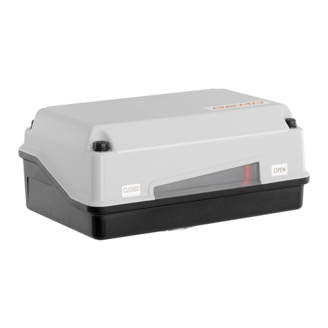
The product is a motorized quarter turn actuator. The actuator
is designed for DC or AC operating voltages. A manual over-
ride and an optical position indicator are integrated as stand-
ard. The torque in the end positions is increased. This enables
a closing curve matched to the valves.
3.3 Function
The GEMÜ 9428 motorized quarter turn actuator is a compact
design. The motor and gear are combined as one unit in
aplastic housing. The quarter turn actuator is designed for
use with AC or DC operating voltages and utilises a DC motor
with a secondary spur gear. The 90° movement is achieved by
a ball screw and lever based on the scotch yoke principle. An
optical position indicator and a manual override are integrated
as standard. The end positions are adjustable by means of
microswitches. In the end positions, the motor is stopped im-
mediately by a short circuit in the rotor. The limit switches are
mounted on a switch mounting plate and are adjustable. Thus
an opening and closing limitation is possible. When adjusting
the end positions, a distance of approx. 0.5 - 1 mm must be
ensured in the switching lever of the respective end positions.
The power supply can be 12 V / 24 V DC or 12 V / 24 V AC, de-
pending on the version.
4 CONEXO RFID label
NOTICE
Product surface
▶The CONEXO RFID label cannot be read out on metallic
surfaces.
CONEXO RFID label
The CONEXO RFID label can be retrofitted on existing com-
ponents and can also be fitted to products from third-party
suppliers. The CONEXO RFID label must be ordered separately
and affixed to the desired component for this purpose.
4.1 Construction
RFID label
RFID chip
Transfer paper
4.2 Assembly
1. Degrease the surface of the product in the area to be
covered.
2. Pull the transfer paper off the RFID label.
3. Affix the RFID label to the appropriate place on the
product.
5 Correct use
DANGER
Danger of explosion!
▶GRisk of death or severe injury.
●Do not use the product in potentially
explosive zones.
WARNING
Improper use of the product!
▶Risk of severe injury or death.
▶Manufacturer liability and guarantee will be void.
●Only use the product in accordance with the operating
conditions specified in the contract documentation and in
this document.
The product is not intended for use in potentially explosive
areas.

6 Order data
The order data provide an overview of standard configurations.
Please check the availability before ordering. Other configurations available on request.
Order codes
1 Type Code
Motorized quarter turn actuator,
optical position indicator,
manual override
9428
2 Fieldbus Code
Without 000
3 Actuator use Code
Accessory Z
4 Actuator connection Code
Flange type DIN EN ISO 5211, F03 F03
Flange type DIN EN ISO 5211, F04 F04
Flange type DIN EN ISO 5211, F05 F05
Flange type G05 G05
5 Location spigot Code
Without location spigot N
With location spigot Y
6 Coupling and wrench size Code
Star, WAF 8 mm S08
Star, WAF 9 mm S09
Star, WAF 11 mm S11
Star, WAF 14 mm S14
7 Voltage/Frequency Code
12 V DC B1
12 V/50 - 60 Hz B4
24 V DC C1
24 V 50/60 Hz C4
8 Control module Code
ON/OFF actuator A0
OPEN/CLOSE control, 2 additional potential-free limit
switches,
Class A (EN15714-2)
AE
9 Actuator version Code
Actuator, motorized, operating time 4s, torque 6Nm,
GEMUE, size 1
supply voltage B1, C1, B4, C4
1006
Actuator, motorized, operating time 11s, torque 15Nm,
GEMUE, size 1
supply voltage B1, C1
1015
Actuator, motorized, operating time 11s, torque 15Nm,
GEMUE, size 2
supply voltage B4, C4
2015
Actuator, motorized, operating time 4s, torque 6Nm,
GEMUE, size 3
supply voltage B1, C1, B4, C4
3006
9 Actuator version Code
Actuator, motorized, operating time 11s, torque 15Nm,
GEMUE, size 3
supply voltage B1, C1
3015
Actuator, motorized, operating time 15s, torque 35Nm,
GEMUE, size 3
supply voltage C1
3035
Actuator, motorized, operating time 15s, torque 55Nm,
GEMUE, size 3
supply voltage C1
3055
10 Type of design Code
1 Hirschmann connector N6R 6598
Parallel operation of several actuators 6410
2 Harting connectors Han 7D 6722
11 CONEXO Code
Without
Integrated RFID chip for electronic identification and
traceability
C
6 Order data
www.gemu-group.com 7 / 34 GEMÜ 9428

Order example
Ordering option Code Description
1 Type 9428 Motorized quarter turn actuator,
optical position indicator,
manual override
2 Fieldbus 000 Without
3 Actuator use Z Accessory
4 Actuator connection G05 Flange type G05
5 Location spigot Y With location spigot
6 Coupling and wrench size S08 Star, WAF 8 mm
7 Voltage/Frequency C1 24 V DC
8 Control module A0 ON/OFF actuator
9 Actuator version 1006 Actuator, motorized, operating time 4s, torque 6Nm,
GEMUE, size 1
supply voltage B1, C1, B4, C4
10 Type of design 6598 1 Hirschmann connector N6R
11 CONEXO Without
6 Order data
www.gemu-group.com8 / 34GEMÜ 9428

7 Technical data
7.1 Temperature
Ambient temperature: -10 — 60 °C
Storage temperature: 0 — 40 °C
7.2 Product compliance
Machinery Directive: 2006/42/EC
EMC Directive: 2014/30/EU
Low Voltage
Directive:
2014/35/EU
7.3 Electrical data
Duty cycle: Continuous duty
Electrical protection: Motor protective system by customer
Electrical protection
class:
I (DIN EN 61140)
Output signal: Potential-free limit switches (change-over contact 250 V AC/6 A)
7.3.1 Electrical connection
Electrical connection
type:
Cable connection PG 13.5
Binder RD24 flange plug series 693, number of poles: 6+PE, IP67 (GEMÜ 3006, 3015)
Cable diameter: 7.5 — 12.5 mm
Max. cross section of wire: 1.5 mm²
Recommended motor
protection:
Voltage 12 V DC 24 V DC
Motor protection switch type Siemens 3RV 1011-1CA10 Siemens 3RV 1011-1BA10
Set current 2.20 1.70
Current data in A
Rated voltage: 12 V / 24 V AC or DC (± 10 %)
Rated frequency: 50/60 Hz (at AC rated voltage)
Power consumption: Actuator version 12 V DC 12 V AC 24 V DC 24 V AC
Code B1 Code B4 Code C1 Code C4
1006, 3006 30.0 30.0 30.0 30.0
1015, 3015 30.0 - 30.0 -
2015 - 30.0 - 30.0
3035 - - 30.0 -
3055 - - 40.0 -
Power consumption in W
GEMÜ 9428www.gemu-group.com 9 / 34
7 Technical data

Current consumption: Actuator version 12 V DC 12 V AC 24 V DC 24 V AC
Code B1 Code B4 Code C1 Code C4
1006, 3006 2.2 2.0 1.20 1.5
1015, 3015 2.2 - 1.20 -
2015 - 2.0 - 1.2
3035 - - 1.30 -
3055 - - 1.65 -
Current data in A
Max. current at start up: Actuator version 12 V DC 12 V AC 24 V DC 24 V AC
Code B1 Code B4 Code C1 Code C4
1006, 3006 6.3 2.4 4.0 1.8
1015, 3015 9.2 - 3.8 -
2015 - 2.3 - 1.8
3035 - - 3.3 -
3055 - - 7.0 -
Current data in A
7.4 Mechanical data
Installation position: Optional
Protection class: GEMÜ 1006, 1015, 2015, 3035, 3055:
IP 65 acc. to EN 60529
GEMÜ 3006, 3015:
IP 67 acc. to EN 60529
Weight: Supply voltage 12 V / 24 V: 1.0 kg
Actuator version 3055: 2.8 kg
Manual override: with Allen key SW3
Torques: Actuator version 1006, 3006: 6 Nm Actuator version 1015, 2015, 3015: 15 Nm
Actuator version 3035: 35 Nm
Actuator version 3055: 55 Nm
Operating time: Actuator version 1006, 3006: approx. 4 s Actuator version 1015, 2015, 3015: approx. 11 s Actuator
version 3035 / 3055: approx. 15 s
Nominal travel: 90°
Max. travel: 93°
Setting range: 0 to 20° (limit switch Min.)
70 to 93° (limit switch Max.)
www.gemu-group.com10 / 34GEMÜ 9428
7 Technical data

8 Dimensions
8.1 Actuator version 1006, 1015, 2015
A
145,0
40,0
80,0
55,0
C
62,0*
80.0
62.0 55.0
145.0
40.0
Actuator ver-
sion
A C
1006, 1015 94.0 49.0
2015 122.0 53.0
Dimensions in mm
8.2 Actuator version 3006, 3015
ON/OFF actuator (control module code A0)
94,0
62,9
43,2
S1/S2 UV
99.6
61.9
154.8
76.9
20.6
45.0
43.2
5.0
6.29
94.0
OPEN/CLOSE control, 2 additional potential-free limit switches (control module code AE)
94,0
62,9
43,2
99.6
61.9
154.8
76.9
20.6
45.0
43.2
94.0
62.9
Dimensions in mm
GEMÜ 9428www.gemu-group.com 11 / 34
8 Dimensions

8.3 Actuator version 3035, 3055
66,0 76,0
172,0 208,0
94,0
A
172.0
66.0 76.0
208.0
94.0
100.5
Dimensions in mm
8.4 Connection dimensions actuator version (10XX, 20XX, 30XX)
LK
G
SW
T
DIN ISO 5211
Actuator version
(code)
Connection size
(code)
Location spigot
(code)
SW G LK T
1006, 1015, 2015,
3006, 3015
G05 Y S08 Ø5.5 48.0 15.0
F03 N S09 M5 36.0 16.0
F04 N S09 M5 42.0 16.0
F05 N S09 M6 50.0 16.0
F05 N S11 M6 50.0 16.0
3035, 3055 F05 Y S14 M6 50.0 22.0
Dimensions in mm
www.gemu-group.com12 / 34GEMÜ 9428
8 Dimensions

www.gemu-group.com 13 / 34 GEMÜ 9428
9 Manufacturer's information
9.1 Delivery
●Check that all parts are present and check for any damage
immediately upon receipt.
The product's performance is tested at the factory. The scope
of delivery is apparent from the dispatch documents and the
design from the order number.
9.2 Transport
1. Only transport the product by suitable means. Do not drop.
Handle carefully.
2. After the installation dispose of transport packaging ma-
terial according to relevant local or national disposal regu-
lations / environmental protection laws.
9.3 Storage
1. Store the product free from dust and moisture in its ori-
ginal packaging.
2. Avoid UV rays and direct sunlight.
3. Do not exceed the maximum storage temperature (see
chapter "Technical data").
4. Do not store solvents, chemicals, acids, fuels or similar
fluids in the same room as GEMÜ products and their spare
parts.
10 Electrical connection
DANGER
Risk of electric shock!
▶Risk of injury or death (if operating
voltage is higher than safe extra low
voltage).
▶Adjustments are made with the actu-
ator cover removed.
▶Electric shock can cause severe burns
and fatal injury.
●Always disconnect the product from
power supply!
●Therefore, have all work performed
only by qualified electricians.
CAUTION
●Power supply varies dependent on the
design (see product label).
●Do not bridge terminals!
●For parallel connection of several actu-
ators, use the version with K-no. 6410.
●With version AE (additional potential-
free limit switches), the plug connec-
tions must not be interchanged with
the power supply.
NOTICE
Required for electrical connection:
●Allen key size SW3
●Small flat screw driver
1. Disconnect the plant from power supply.
2. Remove the protective caps 1.
3. Unscrew cable entry 2.
4. Undo screws 3.
5. Do not lose the washers 4.
6. Disassemble the cover of the actuator 5.
7. Insert cable through cable entry 2.
Remove internal sealing ring if necessary.
8. Connect cable (see chapter "Connection diagram 12 / 24
V" and chapter "Connection diagram 100 - 250V").
9. Put on cover of actuator 5.
10. Tighten cover 5.
11. Put on protective caps 1.
12. Screw down cable entry 2.
10 Electrical connection

10.1 Connection/wiring diagram
10.1.1 ON/OFF actuator (code A0)
12 V AC (code B4) / 24 V AC (code C4)
Assignment of the terminal strips
1
2
3
4
5
Item Description
1 L1, supply voltage
2 N, supply voltage
3 L1, change-over (OPEN/CLOSED)
4 N, change-over (OPEN/CLOSED)
5 PE, protective earth conductor
Preferred direction -OPEN- when all signals are present
Connection diagram
External
wiring
Terminal strip
Limit switch OPEN
Limit switch CLOSED
Motor
Uv L1
N
PE
S1 S2
1
2
3
4
5
S1 Actuator
0 OFF
1 ON
S2 Direction of travel
0 CLOSED
1 OPEN
www.gemu-group.com14 / 34GEMÜ 9428
10 Electrical connection

12 V DC (code B1) / 24 V DC (code C1)
Position of the connectors
S1/S2 UV
Actuator version
3006, 3015
Electrical connection
13
2
654
Plug assignment UV
Pin Description
1Uv+, direction of travel CLOSED
2Uv-, direction of travel CLOSED
3Uv+, direction of travel OPEN
4Uv-, direction of travel OPEN
5n.c.
6n.c.
PE, protective earth conductor
Connection diagram
S3
Uv
13
2
65
4
CLOSED-0-OPEN
External
wiring
Connection assignment X1, UV
S3 Actuator
CLOS
ED
Direction of travel CLOSED
0 OFF
OPEN Direction of travel OPEN
GEMÜ 9428www.gemu-group.com 15 / 34
10 Electrical connection

12 V DC (code B1) / 24 V DC (code C1) / K-no. 6598
Position of the connectors
X1
Electrical connection
21
3
4
6
5
Plug assignment X1
Pin Description
1 Uv+, direction of travel CLOSED
2 Uv-, direction of travel CLOSED
3 Uv+, direction of travel OPEN
4 Uv-, direction of travel OPEN
5 n.c.
6 n.c.
PE, protective earth conductor
Connection diagram
S3
Uv
12
6
5
3
4
CLOSED-0-OPEN
External
wiring
S3 Actuator
CLOSED Direction of travel CLOSED
0 OFF
OPEN Direction of travel OPEN
www.gemu-group.com16 / 34GEMÜ 9428
10 Electrical connection

12 V AC (code B4) / 24 V AC (code C4) / K-no. 6598
Position of the connectors
X1
Electrical connection
21
3
4
6
5
Plug assignment X1
Pin Description
1 L1, supply voltage
2 N, supply voltage
3 L1, change-over (OPEN/CLOSED)
4 N, change-over (OPEN/CLOSED)
5 n.c.
6 n.c.
PE, protective earth conductor
Preferred direction -OPEN- when all signals are present
Connection diagram
S2
S1
Uv
1 2
6
5
3
4
L1 N
0 1
0 1
External
wiring
S1 Actuator
0 OFF
1 ON
S2 Direction of travel
0 CLOSED
1 OPEN
GEMÜ 9428www.gemu-group.com 17 / 34
10 Electrical connection

12 V DC (code B1) / 24 V DC (code C1) / K-no. 6410
Assignment of the terminal strips
1
2
3
4
5
Item Description
1 Uv+, direction of travel CLOSED
2 Uv-, direction of travel CLOSED
3 Uv+, direction of travel OPEN
4 Uv-, direction of travel OPEN
5 PE, protective earth conductor
Connection diagram
PE
1
2
3
4
5
S3
Uv
1
2
3
4
5
Actuator
Actuator
(Actuator)
(Actuator)
Motor
Motor
S3 Actuator
CLOSED Direction of travel CLOSED
0 OFF
OPEN Direction of travel OPEN
www.gemu-group.com18 / 34GEMÜ 9428
10 Electrical connection

12 V DC (code B1) / 24 V DC (code C1)
Assignment of the terminal strips
1
2
3
4
5
Item Description
1 Uv+, direction of travel CLOSED
2 Uv-, direction of travel CLOSED
3 Uv+, direction of travel OPEN
4 Uv-, direction of travel OPEN
5 PE, protective earth conductor
Connection diagram
+− PE
1
2
3
4
5
0
S3
Limit switch OPEN
Limit switch CLOSED
Terminal strip
CLOSED
OPEN
Motor
External
wiring
S3 Actuator
CLOSED Direction of travel CLOSED
0 OFF
OPEN Direction of travel OPEN
GEMÜ 9428www.gemu-group.com 19 / 34
10 Electrical connection

12 V DC (code B1) / 24 V DC (code C1) / K-no. 6410
NOTICE
Parallel operation
▶Parallel operation only possible with K-no. 6410.
Assignment of the terminal strips
1
2
3
4
5
Item Description
1 Uv+, direction of travel CLOSED
2 Uv-, direction of travel CLOSED
3 Uv+, direction of travel OPEN
4 Uv-, direction of travel OPEN
5 PE, protective earth conductor
Connection diagram
PE
1
2
3
4
5
S3
Uv
1
2
3
4
5
Actuator
Actuator
(Actuator)
(Actuator)
Motor
Motor
S3 Actuator
CLOSED Direction of travel CLOSED
0 OFF
OPEN Direction of travel OPEN
www.gemu-group.com20 / 34GEMÜ 9428
10 Electrical connection
This manual suits for next models
11
Table of contents
Other GEM Controllers manuals