manuals.online logo
Brands
  1. Home
  2. •
  3. Brands
  4. •
  5. Zennio
  6. •
  7. Controllers
  8. •
  9. Zennio LUMENTO X3 Guide

Zennio LUMENTO X3 Guide


LUMENTOX3
LEDDIMMING
RGBCONTROLLER
ZN1DI‐RGBX3        
TechnicalDocumentation

© Zennio Avance y Tecnología S.L. Edition 4 Further information www.zennio.com
Page 1/ 2
1
3
2
6
4
7
5
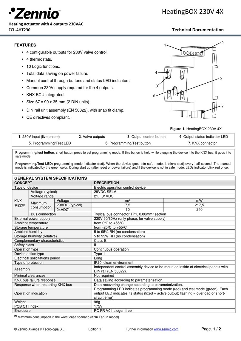
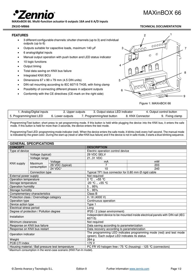
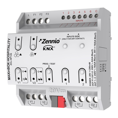
MAIN FEATURES
Control of RGB LEDs or 3 independent channels.
External power supply required (12-24 VDC).
LEDs test function
KNX BCU integrated
KNX and CE mark
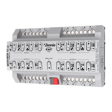
SIZE AND DESCRIPTION
N Element
1 KNX Connector
2 KNX Programming button
3 KNX Programming and internal test LED
4 Test button
5 Test LED and Reversed polarity indicator
6 External power supply terminal block
7 LEDs control terminal block
GENERAL SYSTEM SPECIFICATIONS
Type of device Electric Operation Control Device
KNX Supply
Voltage 29V DC SELV
Voltage range 20…31V DC
Power consumption 145 mW
Bus connection Typical BUS connector TP1, 0.50mm2 section
External Power Supply 12 – 24V DC
Power Supply cable section 1.5 mm² to 2.5 mm²
Type of control PWM (150, 300, 488 ó 600 Hz)
Ambient Temperature 0ºC to +45ºC
Storage Temperature -5ºC a +50ºC
Ambient Humidity 30 to 85% RH (no condensation)
Storage Humidity (relative) 30 to 85% RH (no condensation)
Complementary Characteristics Class B
Safety Class II
Operation Type Continuous operation
Device Action Type Type 1
Electrical solicitations period Long
Type of Protection IP20
Assembly Independent control assembly device
Connect Lumento as near as possible to both, the LED to dimmer and the external power supply
Power Failure response (bus) Data saving
Response when restarting (bus) Data saving
KNX Programming button: a push button to set the programming mode. If this button is held while plugging the device into the
KNX bus, it goes into secure mode.
KNX Programming and internal test LED: the red LED indicates programming mode. When the device goes into secure mode, it
blinks red every 0.5 seconds. The blinking blue LED indicates internal test.
Test button: it tests the functioning of channels connected to the device. Push and hold for 3 seconds to get in/out of the testing
mode.
Test LED and polarity: tricolored LED that indicates which channel (red=channel 1/R, green=channel 2/G, blue=channel 3/B) is
being tested. White light indicates that the device is in test mode. Orange light indicates reverse polarity in external power supply.


LUMENTOX3
LEDDIMMING
RGBCONTROLLER
ZN1DI‐RGBX3        
TechnicalDocumentation

© Zennio Avance y Tecnología S.L. Edition 4 Further information www.zennio.com
Page 2/ 2
WIRING AND ASSEMBLY DIAGRAMS
Recommended installation: NOT recommended:
Verticalposition.
If there is not any other
possibility, install
terminal block up
(see fig.)
SAFETY INSTRUCTIONS
Do not connect Mains Voltage (230 V) or any other external voltages to any point of the BUS. Connecting an external voltage
might put the entire KNX system at risk.
Make sure during the installation that there is always sufficient insulation between the mains voltage 230V and the bus or the
extension inputs.
When Overheating protection is active, the device will decrease the luminosity level and control frequency. Further information,
please read manual.
The voltage of the power supply connected to Lumento will never exceed the voltage required for the load, which is specified
by the manufacturer. Not following this recommendation would mean a risk for the installation.
Operation indication
Programming/internal test LED indicates: programming mode (red lighting), safe mode (red
blinking) and internal test (blue blinking). Test LED indicates: White, device in test mode; Red, test
channel 1 (R); Green, test channel 2 (G); Blue, test channel 3 (B). Reverse polarity of external
power supply is indicated by the Test LED with orange light.
PCB CTi index 175 V
Enclosure PC-ABS, flammability category Class D
Size Without terminal blocks: 144x44x22mm / With terminal blocks: 157x44x22mm
Weight 102 g.
OUTPUTS SPECIFICATIONS AND CONNECTIONS
Maximum current per channel 2.5A @ 25ºC ambient temperature
Number of channels 3
Total power connected 90W (12V DC) or 180W (24V DC)
Connection Type Terminal block (screw)
Cable Section 1.5 mm² to 2.5 mm²
Load type Common anode
Shortcut protection Yes
Overheating protection Yes
External power supply:
+ and - terminals of
external power supply 12-
24 VDC

LEDs
The LEDs load is connected to the terminal block, matching the anode or the anode
common terminal of the LED stripes with C (anode)
Correspondence
C: Anode 2: Green 1: Red 3: Blue 4: - s
p
are -
A
ssembly:
Screw mounting, 2 holes of 3.5 mm
diameter. Screws not included.

This manual suits for next models

1

Other Zennio Controllers manuals

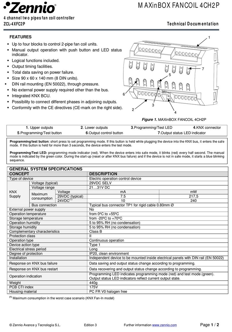
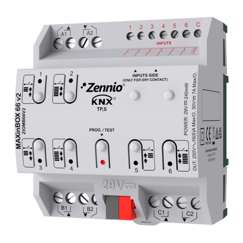
Zennio MAXinBOX66 Guide

Zennio

Zennio MAXinBOX66 Guide

Zennio IRSC Plus User manual

Zennio

Zennio IRSC Plus User manual

Zennio FANinBOX 110V 1CH Guide

Zennio

Zennio FANinBOX 110V 1CH Guide

Zennio MAXinBOX 24 v2 Guide

Zennio

Zennio MAXinBOX 24 v2 Guide

Zennio MAXinBOX SHUTTER 8CH v3 Guide

Zennio

Zennio MAXinBOX SHUTTER 8CH v3 Guide

Zennio MINiBOX 25 v3 Guide

Zennio

Zennio MINiBOX 25 v3 Guide

Zennio IDAC User manual

Zennio

Zennio IDAC User manual

Zennio MINiBOX 45 v3 Guide

Zennio

Zennio MINiBOX 45 v3 Guide

Zennio MAXinBOX User manual

Zennio

Zennio MAXinBOX User manual

Zennio ZN1DI-RGBX4 User manual

Zennio

Zennio ZN1DI-RGBX4 User manual

Zennio IRSC Zone User manual

Zennio

Zennio IRSC Zone User manual

Zennio ACTinBOX MAX6 User manual

Zennio

Zennio ACTinBOX MAX6 User manual

Zennio ALLinBOX 1612 v2 User manual

Zennio

Zennio ALLinBOX 1612 v2 User manual

Zennio MAXinBOX 24 Guide

Zennio

Zennio MAXinBOX 24 Guide

Zennio DIMinBOX 2CH ZDI-DB2C User manual

Zennio

Zennio DIMinBOX 2CH ZDI-DB2C User manual

Zennio inBOX 24 v2 User manual

Zennio

Zennio inBOX 24 v2 User manual

Zennio MAXinBOX FC 0-10V FAN User manual

Zennio

Zennio MAXinBOX FC 0-10V FAN User manual

Zennio Tecla 55 X Sign User manual

Zennio

Zennio Tecla 55 X Sign User manual

Zennio MAXinBOX 8 Guide

Zennio

Zennio MAXinBOX 8 Guide

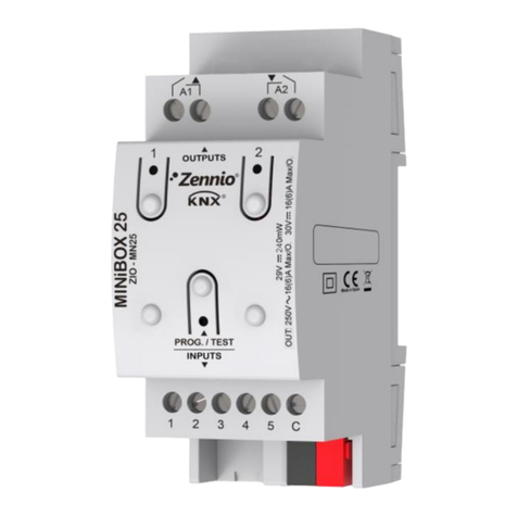
Zennio MINiBOX 25 Guide

Zennio

Zennio MINiBOX 25 Guide

Zennio HeatingBOX 24V 4X User manual

Zennio

Zennio HeatingBOX 24V 4X User manual

Zennio Tecla 55 User manual

Zennio

Zennio Tecla 55 User manual

Zennio MAXinBOX FANCOIL 4CH2P Guide

Zennio

Zennio MAXinBOX FANCOIL 4CH2P Guide
Zennio Roll-ZAS User manual

Zennio

Zennio Roll-ZAS User manual

Popular Controllers manuals by other brands

Siemens Climatix HMI-TM Basic documentation

Siemens

Siemens Climatix HMI-TM Basic documentation

MEDENUS R 51 Operating and maintenance instructions

MEDENUS

MEDENUS R 51 Operating and maintenance instructions

Icar RPC 8BGA operating manual

Icar

Icar RPC 8BGA operating manual

Mitsubishi Electric PAC-YT34STA user guide

Mitsubishi Electric

Mitsubishi Electric PAC-YT34STA user guide

Omron CJ2 Series Network Connection Guide

Omron

Omron CJ2 Series Network Connection Guide

AudioCodes Mediant 4000 E-SBC Hardware installation manual

AudioCodes

AudioCodes Mediant 4000 E-SBC Hardware installation manual

Winext WLC-NEMA-01 user manual

Winext

Winext WLC-NEMA-01 user manual

Hummingbird APEX 13 installation guide

Hummingbird

Hummingbird APEX 13 installation guide

InelControl ORS-01IC Installation and operation manual

InelControl

InelControl ORS-01IC Installation and operation manual

Gewiss Chorus GW 90 836A manual

Gewiss

Gewiss Chorus GW 90 836A manual

Emerson FISHER 657 instruction manual

Emerson

Emerson FISHER 657 instruction manual

gefran eView BOX Quick installation guide

gefran

gefran eView BOX Quick installation guide

DSC PowerSeries Neo 3G8080I installation manual

DSC

DSC PowerSeries Neo 3G8080I installation manual

MegaSquirt DBWX2 Abridged user manual

MegaSquirt

MegaSquirt DBWX2 Abridged user manual

Aprilaire 56 Safety and installation instructions

Aprilaire

Aprilaire 56 Safety and installation instructions

Danfoss AMV 438 SU installation guide

Danfoss

Danfoss AMV 438 SU installation guide

St. Jude Medical 3875 user guide

St. Jude Medical

St. Jude Medical 3875 user guide

IAI ssel Operation manual

IAI

IAI ssel Operation manual

manuals.online logo
manuals.online logoBrands
  • About & Mission
  • Contact us
  • Privacy Policy
  • Terms and Conditions

Copyright 2025 Manuals.Online. All Rights Reserved.