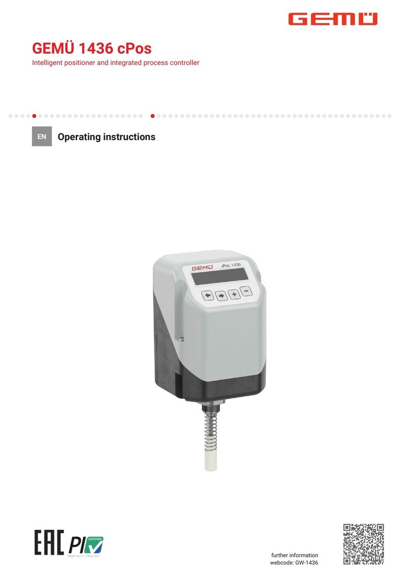
GEM DG-2000 Series User manual

GEM
DG-2000 Series Standalone PROX Reader Controller Operation Manual
__________________________________________________________________________
_______________________________________________________________________________________________________________
Version 1. 05-22-2015 Gianni Industries, Inc. Page 1 of 17
1. FEATURES
2. TECHNICAL SPECIFICATIONS
3. INSTALLATION DIAGRAMS
4. PARAMETERS SETUP
Enter and Exit the program mode
Reset to factory setting
Change master password
Change door common access password
Setup operation mode
Setup current time
Setup time interval function of electrified lock released
Setup time interval function of No password entry needed
Setup time interval function for disabling alarm
Enable time interval function of No password entry needed (option)
Enable time interval function of disabling alarm (option)
Enable time interval function of electrified lock released (option)
Enable door ajar function
Enable alarm function
5. Adding Card and Door Access PIN
Add master card
Add user card
Add door access PIN
6. Deleting Card and Door Access PIN
Delete master card
Delete user card
Delete door access PIN
Empty location ID
Delete all master cards
Delete all user cards
Delete all door access PINs
7. USERS LIST
8. NOTES
9. HOW TO ORDER

GEM
DG-2000 Series Standalone PROX Reader Controller Operation Manual
__________________________________________________________________________
_______________________________________________________________________________________________________________
Version 1. 05-22-2015 Gianni Industries, Inc. Page 2 of 17
DG-2100EU
DG-2000US
1. General Features:
◇DG-2000US / DG-2100EU are standalone PROX
reader controllers.
◇ DG-2000US is designed for universal standard
size configuration, particularly for ANSI standard
size.
DG-2000EU is designed for Asian or European
standard size configuration.
◇ Weatherproof designed and vandal resistant.
◇ The tactile keys with audible keypad applies touch sensor technology compared with traditional
physical rubber keypad and overcomes any possible mechanical problems.
◇ Infra-red light tamper design overcomes possible mechanical problems.
◇ Optional readers are capable of securing external installation. The reader output should be in
wiegand 32-bit, keypad output should be in 4 / 6 / 8 bits format.
◇ 3 operation modes: (1.) Card and PIN, (2.) Card or PIN, (3.) PIN only.
◇ Up to 5 Master cards can be registered onto DG-2000US / DG-2000EU. If a user forgets his
Master password, just tap in **,< Use the Master card >, and #to enter the program mode.
The Master card is also equal to a valid access card.
◇ 2000-cardholder capacity. 32-bit card serial number which can be saved at a memory location
from 1 to 2000.
◇ 200 Door Access PINs. The length of a PIN number is capable from 1 to 6 digits, and you can
set the value from 0 to 999999. A PIN number can be saved at a memory location from 2001 to 2200.
◇ 1 Common Access Password for operation. The length of the password is capable from 0 to
999999 (1 ~ 6 digits).
◇ 1 Master Password. To enter the program mode by key in the Master password or use a Master
card. The Master password is capable from 1 to 8 digits, and you can set the value from 0 to 99999999.
◇ When the yellow LED on the keypad starts flashing, indicating to enter password on the unit.
◇ 3 types of time interval functions: (1) No password entry needed, (2) Electrified lock release time,
and (3) Disabling alarm.
◇ Password lockout threshold. 3 failed attempts in a roll will cause the reader to be locked, and then
the reader cannot be used until 60 seconds.
◇ These 2 reader controllers DG-2000US / DG02000EU, both have two technologies in one system,
125 KHz of low frequency and 13.56 MHz high frequency.
◇ The function of Master Reset is only to reset the Master password but still remain the records of door
access PINs.
Note: If the Card Serial Number (CSN) is more than 32-bit, take the lower 32-bit as the card number,
else leading zero appended.

GEM
DG-2000 Series Standalone PROX Reader Controller Operation Manual
__________________________________________________________________________
_______________________________________________________________________________________________________________
Version 1. 05-22-2015 Gianni Industries, Inc. Page 3 of 17
2. TECHNICAL SPECIFICATIONS:
Keypad Operations
1. System will monitor keypad entry, it will not accept invalid entry
2. Each code entry waiting time is 10 seconds. If time expires, the program will exit with beep sound 5
times.
LED Indicators
Main Reader Controllers Optional Readers
Ready mode
Program
mode
Prompt to
enter
password
Flashing
Yellow
Flashing
Yellow
During
electrified lock
release
Invalid Card
Buzzer Indications
noitpircseDsdnuoSpeeB
1Code entry ; Access is granted
2Return to programming mode
3Access denied ; Invalid password ; Invalid value entry
4Power on, Reset to factory setting
Door Ajar Get a single beep for every 2 seconds until door sensor closed
Sound Duration
Beep Volume noitpircseD
Short 10ms
Medium 20ms
Long 40ms
DG-2100K
Red
Flashing
Yellow
Green
Flashing
Green
DG-2000US DG-2100EU DG-2000R DG-2000K DG-2000SR DG-2100R
Power Voltage 12 to 16 VAC/DC
Operating Current Less than 80mA DC for controller, 1.5A DC for Electrified locks
Operating Temperature
Operating Humidity 0 to 95% non-condensing
RFID Technology EM: 125 KHz
Mifare: 13.56 MHz
Read Range 40mm+ for 13.56 MHz ISO card
80mm+ for 125 KHz ISO card
Response Time
Alarm Output
Relay Specifications 12VDC, 2A DC
Dimensions DG-2100EU 86 x 86 x 21mm, DG-2000US 105 x 80 x 21 mm
Weatherproof Yes
Color
-10°C to +65°C
EM + Mifare
Less than 0.2 seconds
5VDC with 25mA DC
Black
Red Red Blue BlueBlue Red
Yellow Yellow
Green Green Green GreenGreen Green
Red RedRed Red Red
DG-2000SK
Flashing
Green
Blue
Green
Red

GEM
DG-2000 Series Standalone PROX Reader Controller Operation Manual
__________________________________________________________________________
_______________________________________________________________________________________________________________
Version 1. 05-22-2015 Gianni Industries, Inc. Page 4 of 17
3. Installation Diagrams:
Secure Mode
PSM-25T
Optional
Reader
DG-2000US
EM+Mifare
Stand Alone
Power Supply
or
DG-2100EU
Inside
EXIT ENTRY
Outside
DG-2000K
or
DG-2100K
(Built-in locking timer controller)
Two Technology In One Keypad Controller
(EM: Low Frequency)
(Mifare: High Frequency)
Prox Reader Controller
Normal Mode Power
Supply
PSU310
DG-2000US
EM+Mifare
Standalone
Request
to
Exit
Button
PBT-800
or
AS-500
or
DG-2100EU
Inside
EXIT ENTRY
Outside
(EM: Low Frequency)
(Mifare: High Frequency)
Prox Reader Controller
Magnetic
Lock GEM-800
Magnetic
Lock GEM-800
CP-31GP
Call Point
CP-31GP
Call Point

GEM
DG-2000 Series Standalone PROX Reader Controller Operation Manual
__________________________________________________________________________
_______________________________________________________________________________________________________________
Version 1. 05-22-2015 Gianni Industries, Inc. Page 5 of 17
Electrified Locks Applications
GEM-800 Magnetic Lock (800 lbs) GK300 Electric Strike
EB220N Electric Dropbolt EB261 Fail-Secure
Electric Latch Bolt
GK530/540
European Profile Strike
LS2200 Latch Bolt
(http://www.gianni.com.tw/ElectromagneticLock-gem800.asp) (http://www.gianni.com.tw/ElectricStrike-gk300.asp)
(http://www.gianni.com.tw/ElectricDropbolt-eb220n.asp)
(http://www.gianni.com.tw/ElectricDropbolt-eb261.asp)
(http://www.gianni.com.tw/ElectricStrike-gk540.asp)
(http://www.gianni.com.tw/Accessories-door-latch.asp)

GEM
DG-2000 Series Standalone PROX Reader Controller Operation Manual
__________________________________________________________________________
_______________________________________________________________________________________________________________
Version 1. 05-22-2015 Gianni Industries, Inc. Page 6 of 17
PIN ASSIGNMENTS
PIN# Definition Description
P1-1 RS485 (A) RS485 (A) connect to PC or connect to a 2nd controller
P1-2 RS485 (B) RS485 (B) connect to PC or connect to a 2nd controller
P1-3 Buzzer For external reader BUZZER
P1-4 Green LED For external reader GREEN LED
P1-5 D0 For external reader Data 0
P1-6 D1 For external reader Data 1
P1-7 Earth
Ground For external reader Earth Ground
P1-8 Power For external reader Power
PIN# Definition Description
P2-1 9-16VIN Power supply, 12V~16VAC/DC
P2-2 GND Earth Ground
P2-3 ALARM Alarm output: 5VDC ; 0VDC is normal status
P2-4 RTE Request to Exit
P2-5 SENSOR Door Sensor
P2-6 NC Relay Normal Close (N.C.), dry contact
P2-7 COM Relay Common (COM.), dry contact
P2-8 NO Relay Normal Open (N.O.), dry contact
Back View
P1P2
1
2
3
4
5
6
7
8
1
2
3
4
5
6
7
8
GEM
DG-2100EU
P1
485-A
485-B
R-BUZZER
R-LED
R-D0
R-D1
R-GND
R-VCC
1
2
3
4
5
6
7
8
P2
9-16VDC
GND
ALARM
RTE
SENSOR
LOCK-NC
LOCK-COM
LOCK-NO
1
2
3
4
5
6
7
8

GEM
DG-2000 Series Standalone PROX Reader Controller Operation Manual
__________________________________________________________________________
_______________________________________________________________________________________________________________
Version 1. 05-22-2015 Gianni Industries, Inc. Page 7 of 17
Standalone / Networked Reader Controller External Device Connection Diagram
P2 P1
RS485 A
RS485 B
External reader BUZZER
External reader LED
External reader Data 0
External reader Data 1
External reader Ground
External reader Power
Fail-Secure Fail-Safe
12VDC
PBT-800
AS-500
+
-
Must install a Diode
DG-2000US / 2100EU Controller
+
-
1
2
3
4
5
6
7
8
Alarm out at 5 VDC
Normal is 0 VDC
Must install a Diode
1
2
3
4
5
6
7
8
Power Supply Unit
Exit Button Exit Button
Wiring diagram:
INPUT
100~240VAC
L
N
P.B
GND
12VDC
1A
12VDC
1.5A
N.O
COM
-
+
-
+
N.C N.O
Timer
0~45S
N.O
COM
-
+
(Timed)
PSM-25T
Exit Button
(or PSM-26T)
N.C. (Fail-safe)/N.O.(Fail-secure) Switchable
PBT-800
AS-500 ANSI Size
European Standard Size

GEM
DG-2000 Series Standalone PROX Reader Controller Operation Manual
__________________________________________________________________________
_______________________________________________________________________________________________________________
Version 1. 05-22-2015 Gianni Industries, Inc. Page 8 of 17
4. Setup Parameters
Operation Flow for Setting up DG-2000 Series Standalone PROX Reader Controller
Start
Setup system basic
parameters
Setup time interval
function
(optional)
Add Master card/
User card and door
access PIN
Finish
Make sure all cables are in correct connection before power on
Setup system basic parameters:
Enter the program mode
Reset to factory setting
Change master password
Change door common access password
Setup operation mode
Setup current time
Setup Electrified lock release time
Setup time interval function (option):
Setup time interval for No password entry needed
Setup electrified lock release time interval function
Setup time interval for alarm disabled function
Enable time interval for No password entry needed function (option)
Enable time interval for alarm disabled function (option)
Enable electrified lock release time interval function (option)
Enable door ajar funciton
Enable alarm function
Add master card / user card and door access PIN
Add master card for backup (max. 5 cards)
Add user card (max. 2000 cards)
Add door access PIN (max. 200 PINs)
Operation Begins

GEM
DG-2000 Series Standalone PROX Reader Controller Operation Manual
__________________________________________________________________________
_______________________________________________________________________________________________________________
Version 1. 05-22-2015 Gianni Industries, Inc. Page 9 of 17
Enter / Exit the Programming Mode
1.
(Default master password = 12345678)
2.
3.
Reset to Factory Setting
1. Press: *
*
801#801# (Clear all users information and reset to factory setting)
2. Press:
*
*
802#802# (Remain users information but reset to factory setting)
Change Master Password
Press: *
*
9New Master Password # New Master Password #
NOTE: Master Password length is 1 to 8 digits
Change Door Common Access Password
Press: *
*
82 Common Access Password # Common Access Password #
Default Common Access Password is “111111”
NOTE: Common Access Password length is 1 to 6 digits
Setting User Modes
Install DG-2000US or DG-2100EU controller at outdoor area (Normal Mode)
Enter: *
*
01# (Default Setting)
–Require a Card AND Common Access Password entry
Enter: *
*
04#
–Require a Card AND Common Access Password or Door Access PIN for entry (Default)
Enter: *
*
05#
–Require a Door Access PIN for entry only
Install DG-2000US or DG-2100EU controller at indoor area
and install GEM Optional Reader at outdoor area (Secure Mode)
Enter: *
*
02#
-For DG-2000US or DG-2100EU requires a Card only (No Common Access Password for entry
required)
-For outdoor GEM Optional Reader requires a Card AND Common Access Password for entry
Enter: *
*
03#
–For DG-2000US or DG-2100EU requires a Card (No Common Access Password for entry required)
or a Door Access PIN for entry
–For outdoor GEM Optional Reader requires a Card AND Common Access Password or Door Access
PIN for entry
Setting Current Time
Press: *
*
83 HHMMSS #HHMMSS #
Setting Electrified Lock Release Time
Press: *
*
81 Electrified Lock Release Time (00 to 30 seconds) #
Electrified lock release time default setting is 5 seconds
Press:**
**
Master Password or # (Use master card). Reader LED color is Yellow.
Press:**
**
# to exit or 30 seconds timeout to exit automatically to return to ready mode.
In ready mode, entering Master password enables door to open.
First turn off the power of the controller. Keep the RTE and GND wires connected and then turn
on the power. Wait for 5 seconds. The reader will reset master password to “12345678” after 4
short and 1 long beeps.
Master Reset

GEM
DG-2000 Series Standalone PROX Reader Controller Operation Manual
__________________________________________________________________________
_______________________________________________________________________________________________________________
Version 1. 05-22-2015 Gianni Industries, Inc. Page 10 of 17
Setting Time interval of NO Password Entry Needed
During the time period, no password entry needed
Setting time interval (1):
Press: *
*
84 From HHMM # To HHMM #
Setting time interval (2) :
Press: *
*
85 From HHMM # To HHMM #
Setting Time interval of Electrified Lock Released
During the time period, electrified lock is released
Setting time interval (1):
Press: *
*
86 From HHMM # To HHMM #
Setting time interval (2):
Press: *
*
87 From HHMM # To HHMM #
NOTE: Please remember to disable this function before weekend and holiday.
Setting Time Interval For Disabling Alarm
During this period, alarm output is not available
Setting time interval (1):
Press: *
*
88 From HHMM # To HHMM #
Setting time interval (2):
Press: *
*
89 From HHMM # To HHMM #
Enable Time Interval Function of NO Password Entry Needed (Option)
Enable – Press: *
*
34 # Enable the function
Disable – Press: 44# (Default Setting)
Enable Time Interval Function of Electrified Lock Released (Option)
Enable – Press: *
*
35 # Enable the function
Disable – Press: 45# (Default Setting)
Enable Time Interval Function of Disabling Alarm (Option)
Enable – Press: *
*
36 # Enable the function
Disable – Press: 46# (Default Setting)
Enable Door Ajar Function
Enable – Press: *
*
32 Door Ajar Time (00s to 60s) #. If door ajar time expires, beeper will beep
every 2 seconds continuously until door closed properly.
Disable – Press: 42# (Default Setting)
Enable Alarm Function
Enable – Press: *
*
33#
Disable – Press: *
*
43# (Default Setting)
Use valid card + Door Access PIN to reset alarm (if a Door Access PIN entry is required)

GEM
DG-2000 Series Standalone PROX Reader Controller Operation Manual
__________________________________________________________________________
_______________________________________________________________________________________________________________
Version 1. 05-22-2015 Gianni Industries, Inc. Page 11 of 17
5. Adding Card and Door Access PIN
Please prepare a card number list before adding / deleting a card information.
Add Master Card
Press: *
*
10 (use master card) #
NOTE: If continue adding a master card, no need to press
*
10 again.
Press: #to return to program mode and hear 2 beeps, then press
**
#again to exit the program mode.
Add User Card
Press: *
*
11 Location ID #(use user card) or enter 10-digit card number and #(Location ID is from
NOTE:
If continue adding a user card, no need to press
*
11again, only enter Location ID #(use user
card) or enter 10 digits card number and #
If the location ID has cardholder record, the reader will get 4 beeps, continue or return to program
mode by press #
Press: #to return to program mode and hear 2 beeps, press*
*
*
*
#again to exit the program mode.
Add Door Access PIN
Press: *
*
12 Location ID #Door Access PIN # Door Access PIN #. (Location ID is from
‘2001’ to ‘2200’)
NOTE: If continue adding a door access PIN, no need to press
*
12 again, only enter Location ID #
Door Access PIN # Door Access PIN #.
Press: # to return to program mode and hear 2 beeps, press **
**
# again to exit the program mode.
‘1’ to ‘2000’)

GEM
DG-2000 Series Standalone PROX Reader Controller Operation Manual
__________________________________________________________________________
_______________________________________________________________________________________________________________
Version 1. 05-22-2015 Gianni Industries, Inc. Page 12 of 17
6. Deleting Card and Door Access PIN
Delete Master Card
Press: *
*
20 (use master card) #
NOTE: If continue deleting a master card, no need to press
*
20 again, only (use master card)
and press #
Press: #to return to program mode and hear 2 beeps, press**
**
#again to exit the program mode.
Delete User Card
Press: *
*
21 (use user card) or enter 10-digit card number and #.
NOTE: If continue deleting a user card, no need to press
*
21 again, only (use user card) or
key in 10-digit card number and #.
Press: #to return to program mode and hear 2 beeps, press**
**
# again to exit the program
mode.
Delete Door Access PIN
Press: *
*
22 Door Access PIN # Door Access PIN #.
NOTE : If continue deleting a user card, no need to press
*
22 again, only enter Door Access
PIN #Door Access PIN #.
Press: #to return to program mode and hear 2 beeps, press **
**
# again to exit the program
mode.
Empty Location ID
Press: *
*
23 Location ID #Location ID #.
(Location ID is from ‘1’ to ‘2200’)
NOTE : If continue erasing Location ID contents, no need to press*
*
23 again, only enter Location
ID #Location ID #.
Press: #to return to program mode and hear 2 beeps, press**
**
#again to exit the program mode.
Delete all Master Cards
Press: *
*
27#27#
Delete all User Cards
Press: *
*
28#28#
Delete all Door Access PINs
Press: *
*
29#29#

GEM
DG-2000 Series Standalone PROX Reader Controller Operation Manual
__________________________________________________________________________
_______________________________________________________________________________________________________________
Version 1. 05-22-2015 Gianni Industries, Inc. Page 13 of 17
7. Users List
IMPORTANT NOTICE: Please update the card numbers and PINs for reference.
Card Number Table (2000 Cardholders)
Location ID Card Number User Name Expiration Date
1
2
3
.
.
.
.
1999
2000
Door Access PIN Table (200 PINs)
Location ID PIN User Name Expiration Date
2001
2002
2003
.
.
.
.
2199
2200

GEM
DG-2000 Series Standalone PROX Reader Controller Operation Manual
__________________________________________________________________________
_______________________________________________________________________________________________________________
Version 1. 05-22-2015 Gianni Industries, Inc. Page 14 of 17
8. NOTES:
a) Please add diode parallel of the electrified lock preventing back E.M.F. to damage the device.
b) Create master card and store at a secure location for backup purpose.
c) Change the master password.
d) No need to enter leading zero for any kind of password, complete entry by pressing the # key.
e) The 200 door access PINs are capable from 1 to 6 digits.
f) Electrified lock release time shall be shorter than the door ajar time.
g)
We suggest that user update the device clock time by monthly.
h) If a user does not return the card to you, please delete the access authority by the location ID.
i)
j)
location.
Make sure the device clock time is correct; especially when you use the time interval control function.
Change the common door access password frequently to enhance and strengthen system security.
Please update the cardholder information and door access PINs information to store at a secure

GEM
DG-2000 Series Standalone PROX Reader Controller Operation Manual
__________________________________________________________________________
_______________________________________________________________________________________________________________
Version 1. 05-22-2015 Gianni Industries, Inc. Page 15 of 17
9. HOW TO ORDER
Main PROX Reader Controllers DG-2000US
DG-2100EU
Optional Readers
DG-2000R
DG-2000SK
DG-2100R
DG-2100K
RF Technology EM + Mifare CSN
RReader without keypad
KReader with keypad
CSN Card serial number
DG-2000K
SR Slim reader without keypad
SK Slim reader with keypad
DG-2000SR
Optional Accessories
Part Number Description
P-CB-10AE
P-CB-8
P-CB-6
P-CB-4
P-CB-2
S-PL-UT
P-PL-UR-3P
PSM-25T
PSM-26T
10 Conductors 24 Gauges
8 Conductors 24 Gauges
6 Conductors 24 Gauges
4 Conductors 22 Gauges
2 Conductors 22 Gauges
2 way butt terminal 0.4~0.9mm wire
3 way butt terminal 0.4~0.9mm wire
Power Supply Unit 1.5A Relock timer for
electrified locks (Field
selectable for Fail-safe
or Fail-secure)
Power Supply Unit
with Cable
Cable for US
Standard Cable For PSM-26T
For PSM-26T
For PSM-26T
Cable for EU
Standard Cable
Cable for UK
Standard Cable

GEM
DG-2000 Series Standalone PROX Reader Controller Operation Manual
__________________________________________________________________________
Version 1. 05-22-2015 Gianni Industries, Inc. Page 16 of 17
_______________________________________________________________________________________________________________
Optional Accessories:
Wires Available:
10 Conductors
(Standard)
24 Gauges
Available Crimp Butt Splice Terminals:
2 way butt terminal
P-CB-10AE
Available Power Supply Units & Power Cables:
S-PL-UT S-PL-UR-3P
0.4~0.9mm wire 3 way butt terminal
0.4~0.9mm wire
Power Supply Unit
PSM-25T PSM-26T
Power Supply Unit
with Cableit US Standard Cable EU Standard Cable UK Standard Cable
Special designed with re-locking timers for electrified locks (Field selectable for Fail-safe or Fail-secure)
P-CB-8 P-CB-6 P-CB-4 P-CB-2
8 Conductors
24 Gauges 6 Conductors
24 Gauges 4 Conductors
22 Gauges 2 Conductors
22 Gauges

GEM
DG-2000 Series Standalone PROX Reader Controller Operation Manual
__________________________________________________________________________
_______________________________________________________________________________________________________________
Version 1. 05-22-2015 Gianni Industries, Inc. Page 17 of 17
Main PROX Reader Controllers
DG-2000US DG-2100EU
DG-2000R
DG-2100R DG-2100K
Optional Readers
DG-2000K
DG-2000SR DG-2000SK
This manual suits for next models
9
Table of contents
Other GEM Controllers manuals
Popular Controllers manuals by other brands

Lights Alive
Lights Alive FireFly FF-511 owner's manual

Kantech
Kantech Door Controller Innovative and Powerful... installation manual

Hayes
Hayes G2 installation manual

SMC Networks
SMC Networks LEKFS G Series instruction manual

Apeks
Apeks GX300 Maintenance manual

Rice Lake
Rice Lake iRite 920i installation instructions