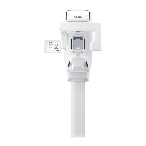
Gendex ORTHORALIX 9200 User manual

Gendex Dental Systems
901 West Oakton Street
Des Plaines, IL 60018 U.S.A.
Tel 1-888-275-5286
Fax 1-847-550-1322
www.gendex.com
Authorized Representative:
KaVo Dental GmbH
Bismarckring 39
88400 Biberach, Germany
www.gendex-dental.com
www.kavo.com
Ceph Installation Manual
Installation Manual
Gendex Dental Systems
901 West Oakton Street
Des Plaines, IL 60018 U.S.A.
Customer Service 1-888-275-5286
Fax 1-847-550-1322
Technical Support 1-888-275-5286
Fax 1-847-718-0716
www.gendex.com
Ceph Installation

Gendex Dental Systems
901 West Oakton Street
Des Plaines, IL 60018 U.S.A.
Tel 1-888-275-5286
Fax 1-847-550-1322
www.gendex.com
Authorized Representative:
KaVo Dental GmbH
Bismarckring 39
88400 Biberach, Germany
www.gendex-dental.com
www.kavo.com
Installation Manual

-iii032-0296-EN Rev 0
Chapter 1 - Ceph Upgrade
Prerequisites ...................................................................................................... 1-1
Installation ......................................................................................................... 1-1
Ceph Wiring ........................................................................................................ 1-4
Ceph Collimator Alignment ................................................................................. 1-5
Secondary Collimator Alignment ......................................................................... 1-7
String Alignment .........................................................................................................1-7
Vertical Alignment of the Secondary Collimator ..........................................................1-9
Install Primary Collimator ................................................................................. 1-10
Check X-ray Alignment with Static Exposure ..................................................... 1-12
Ear Post Alignment ........................................................................................... 1-13
Table of Contents

Table of Contents
032-0296-EN Rev 0-iv

1-11-1
032-0296-EN Rev 0
Chapter
1Ceph Upgrade
Prerequisites
Before starting the installation, make sure the Pan primary collimator alignment is correct.
Installation
The following instructions are for the installation of the Ceph onto a 9200 DDE. The same
procedure is followed for both the new installation of a 9212 DDE and the addition of a
Cephalostat to an existing 9200 DDE. The 9200 DDE can be upgraded to a 9212 DDE with a
Cephalostat at any time.
The Cephalostat requires the installation of a Ceph sensor if the 9200 DDE was originally
ordered without one.
WARNING
High voltage is present in the system. Covers on the equipment should only
be removed by qualified and authorized service personnel. Remove power
from device prior to starting this procedure.
1. Remove the top cover of the overhead assembly.
2.
2 3
Remove the control panel cover (three screws on
top, two on the bottom).
3. Remove the knockout for the mounting of the
ceph arm.

9200 Ceph Installation Manual
032-0296-EN Rev 01-2
4.
4
Remove control panel cover and carefully
unplug the two touch pad control
connections.
NOTE: Do not disconnect ground wire.
5. Place the cover on top of the overhead.
WARNING
The Ceph requires a two person lift. Failure to comply may cause bodily injury.
Two adults are required to position and assemble this unit.
6.
6
Carefully feed all five Ceph cables into the overhead.
7.
7
The cables go through the access hole and up
over the front of the board for connection.

Ceph Upgrade
1-3032-0296-EN Rev 0
8.
8
Level the Ceph arm front to back while
bolting in place (four screws).
NOTE: To facilitate leveling and minimize
later alignment, have an assistant
support the Ceph assembly up and
towards the rear of the Pan while
tightening the mounting bolts.
9.
9
Load all Ceph weights into same place in
column, one large then both taped packets.
10.
10
Remove the shipping bolts and
carriage stop bolt after all components
are mounted and the weights are
inserted into place.

9200 Ceph Installation Manual
032-0296-EN Rev 01-4
Ceph Wiring
1. In the overhead, unplug the
existing connections for X37
and pigtail connections and
replace these connections
with the new arm cable X37
and pigtail.
2. Connect X8 Ethernet cable.
3. Connect X14 arm cable.
4.
4
Install ferrite filter on X-37
and X-8 cables which are
provided in the accessory
box.
5.
5
6
Connect X15 arm cable.
6. Connect X29 arm cable.
1 2
3

Ceph Upgrade
1-5032-0296-EN Rev 0
Ceph Collimator Alignment
NOTE: The ceph plates are NOT installed.
1. Move the collimator lever to the first
ceph position, LL Max (H-22).
2. Remove the front tubehead cover to
uncover the collimator assembly.
NOTE: The brass plate into the Ceph
collimator location is not yet
installed.
3. Remove Ceph cover plate where
collimator is to be installed.
4. Restore power to the device.
5. Move the DMU to the ceph bay.
6. Press the Reset button.
The Reset Light should illuminate.
7. Remove top cover of ceph.
1
3

9200 Ceph Installation Manual
032-0296-EN Rev 01-6
8.
8
8 9
Loosen 4 screws on secondary collimator
plate and adjust plate to the center of the
screws in the slotted mounting holes.
Secure two screws.
9. Loosen 2 screws on the Opto switch flag
and position flag to center screws to center
screws in the slotted mounting holes.
Secure both screws.
10.
10
Loosen the belt tension.
11. Manually move the entire secondary
collimator assembly until the opto switch
flag lines up with the center of the opto
switch.
NOTE: Take notice of the small forward
movement of the assembly as the
belt is tightened and adjust
accordingly.
12. Take care not to put undue tension on the
belt.
13. Press Reset to ensure that the device is
able find the Home position.
14. Power down the device.
15.
a
c
d
b
a
Put the unit into service mode:
a. Press and hold both Patient
Size and Demo Mode buttons
while simultaneously turning
on the power switch. Hold
both buttons until the service
program shows in the window.
b. Use the cuspid directional
buttons to advance through
the service programs to “X-ray
alignment dummy run to go”.
c. Press the Demo Mode button.
d. Press the Reset button.
5. Proceed to the Secondary
Collimator Alignment.

Ceph Upgrade
1-7032-0296-EN Rev 0
Secondary Collimator Alignment
String Alignment
A 70” piece of string or dental floss is
required for this procedure.
1. Tape one end of the string to the
tubehead focal spot located on the
back tubehead cover (raised bump).
2.
2
3
String through the secondary
collimator.
3. Pull the string taut and place the
opposing end on the vertical line of
dots on the DMU.
4. With the line on the dots look at where
the line passes through the collimator.
5. Depending which side the string hits in
the collimator, adjust collimator as
required.
6.
6
7
COLLIMATOR PLATE
Scribe a line on both sides of the
collimator block.
7. Loosen the four screws and move the
collimator plate in the appropriate
direction so the string does not touch
either side of the collimator.
8. Tighten only one of the four screws.
1

9200 Ceph Installation Manual
032-0296-EN Rev 01-8
9.
9
10
Right click the Pan icon in the task bar.
10. Left click Service.
11.
12
11
Click “Stop”
12. Click “Static image”
13. Without the primary, align the secondary collimator with the beam and sensor.
14. After making minor adjustments to bring the beam into the proper position, tighten all four
collimator plate screws.

Ceph Upgrade
1-9032-0296-EN Rev 0
Vertical Alignment of the Secondary Collimator
1. A vertical adjustment (up and down) is made by
loosening the four screw that fix the collimator to the
bar.
2. When the adjustment is made be sure not to over
tighten the screws.
3. Large and small patient positions need to be checked.
4. Verify that the secondary tracks through the whole ceph
scan.
5. Press the patient selector to select “large patient” and
press the “reset” key.
NOTE: If ‘ceph collimator’ appears in the display
window the opto switch flag may need to be
readjusted.
6. Verify that the secondary tracks through the whole ceph scan.
7. Press the patient selector to select “small patient” and press the “reset” key.
SAMLL PATIENT
POSITION
1
LARGE PATIENT
POSITION

9200 Ceph Installation Manual
032-0296-EN Rev 01-10
Install Primary Collimator
1. With the cover plate removed, install the brass collimator plate.
2. Move the plate all the way to the right as a starting point.
3. Confirm that the Ceph collimator lever is set on H-22.
COLLIMATOR LEVER
H22
4. Move the collimator slightly (horizontally) between each exposure (1 mm of the primary
collimator movement =10mm.s of beam movement at the sensor).
5. Remember, service screen, stop/static image, between each shot.
6. If the collimator is aligned, the black bar will have a border all the way around it, and the
Histogram will look like a (Dixie Cup).
7. With the primary lead plate in place, align beam to sensor as shown below.

Ceph Upgrade
1-11032-0296-EN Rev 0
8.
9
Check the vertical alignment by
loosening the two screws that fix the
lead collimator to the brass plate.
9. Move the collimator vertically to center
the beam.
1mm =10 mm at the sensor.
10. When tightening the screws (DO NOT
OVER TIGHTEN).
11. The small and large patient scan
procedure needs to be performed.
12. Select large patient and press reset.
13. Sensor and secondary collimator
moves to the start scan position.
14. Take an exposure.
15. Select small patient and press reset.
16. Sensor and secondary collimator moves to the ending scan position.
17. Take an exposure.
LARGE PATIENT
POSITION
END POSITION
START POSITION
SMALL PATIENT
POSITION
18. The last check and adjustment that is required is the H-18 vertical alignment. Follow the
same procedure as adjusting the H-22.

9200 Ceph Installation Manual
032-0296-EN Rev 01-12
Check X-ray Alignment with Static Exposure
To check the alignment of the X-ray field in panoramic mode proceed as follows:
1. Switch on the unit entering the Service Programs.
2. Select the program X-ray alignment and press Dummy Run;
select 70 kV, 9 mA and 0.16 s: the unit is now ready to make
a static exposure.
3. Select the panoramic position on the collimator and on the
operator panel.
4. Fix the copper filter
(B) supplied on the front part of the DMU
(A) in order to cover completely the digital sensor, by using
adhesive tape.
5. Switch on the PC where the Orthoralix 9200 DDE is
connected.
6. Right click the DDE icon in the system tray; four options are
displayed:
•Remote
•Service
•Reconnect
•Preview
7. Click Service and select Static image.
8. Make an exposure, the following is displayed:
•a white rectangle corresponding to the
digital sensor (the vertical dimension is
compressed)
•a black rectangle corresponding to the
X-ray field
•on the right, three grey sections
showing the position of the X-ray field
respect to the digital sensor.
The purpose is to have the black rectangle in
the middle of the white rectangle, with a white
uniform unexposed area all around. Look at
the following example. or wrong alignment and
how much the lead plate must be adjusted. If
an adjustment (horizontal or vertical) is
required, please refer to the paragraph
Adjusting the X-ray collimator of the Section F
of this Service Manual.
9. For additional exposures, click Stop and then Static image.
10. To exit the Service function, click Stop and then OK.
11. Exit the Service Programs by switching off the system.

Ceph Upgrade
1-13032-0296-EN Rev 0
Ear Post Alignment
1. Install the ceph head positioner parts
2. Use the bottom set of holes on the
side guides only for a pedo practice.
3.
3
In the lateral position place level
under ear posts.
4.
4
Set Ceph earposts to the 160 position.

9200 Ceph Installation Manual
032-0296-EN Rev 01-14
5. Make vertical alignment first, then
the horizontal alignment.
6. This is an acceptable alignment.
7. Congratulations you have
completed the Ceph Installation.

Gendex Dental Systems
901 West Oakton Street
Des Plaines, IL 60018 U.S.A.
Tel 1-888-275-5286
Fax 1-847-550-1322
www.gendex.com
Authorized Representative:
KaVo Dental GmbH
Bismarckring 39
88400 Biberach, Germany
www.gendex-dental.com
www.kavo.com
Installation Manual

Panoramic X-ray System
Installation Manual
Manual de instalación
Installationshandbuch
Manuele d’installazione
Manuel d’installation
Installation Manual
Gendex Dental Systems
1910 North Penn Road
Hatfield, PA 19440 USA
Customer Service: 1-800-323-8029
Fax: 1-847-550-1322
Technical Support: 1-800-769-2909
Fax: 1-847-718-0716
www.gendex.com
Kaltenbach & Voigt GmbH
Bismarckring 39
D-88400 Biberach, Germany
Tel: +49 7351 56 0
Fax: +49 7351 56 1488
e-mail: [email protected]
0413
©2010 Gendex Dental Systems, 032-0296-EN Rev 0 2010 September 15
Other manuals for ORTHORALIX 9200
1
Table of contents
Other Gendex Dental Equipment manuals

Gendex
Gendex AcuCam Concept IV FWT User manual

Gendex
Gendex GXDP-700 User manual

Gendex
Gendex ORALIX AC User manual

Gendex
Gendex ORTHORALIX 8500DDE User manual

Gendex
Gendex eZ1 Installation and operating instructions

Gendex
Gendex DenOptix QST User manual

Gendex
Gendex GXS-700 User manual

Gendex
Gendex VisualiX eHD Troubleshooting guide

Gendex
Gendex ORTHORALIX 8500DDE User manual

Gendex
Gendex GXS-700 User manual