GeneralAire G-99 User manual

The G-99 Air Filter Gage provides a visual indication of the need to replace the air lters in forced
air heating and cooling systems. The gage is installed between the blower and the lter where
a slight vacuum exists due to the air ow resistance of the air lter. Air owing into the gage,
around the calibration screw, lifts a vane in proportion to the negative pressure in the blower
compartment. As the air lter loads, the vacuum increases, raising the vane to indicate a lter
change is necessary.
The gage may be calibrated in a negative pressure range from 0.1 to 0.4 inch w.c. When
properly calibrated in this range a vacuum increase of 0.10 to 0.15 inch w.c. will indicate a lter
change is necessary.
The installer should be an experienced service technician. When drilling the hole in the blower
compartment extreme care should be taken not to damage components within the heating or
cooling system.
The gage must be located where it can sense pressure conditions
in the blower compartment between the lter and the blower.
Select a location on a vertical surface enclosing the blower
compartment and drill a 3/8" hole. Remove the protective paper
from the foam adhesive strip on the back of the gage. Mount the
gage in a level position with the pressure sensing tube projecting
into the blower compartment.
The gage may be remote mounted with a maximum length
of 10 feet of 5/16 inch inside diameter vinyl tubing. Order
remote Kit part No. G99-14
Model G-99 Air Filter Gage
AIR
FILTER
BLOWER
RETURN
AIR
GAGE
®
Installation Manual
F
I
L
T
E
R
I
S
C
L
E
A
N
C
H
A
N
G
E
F
I
L
T
E
R
UP
DOWN
U .S.
PA T.
6190442
®
General Filters, Inc.43800 Grand River Ave., Novi, Michigan 48375 •
Toll Free (866) 476-5101
Phone: (248)476-5100 • Fax (248)349-2366 • www.generalaire.com
APPLICATION
PRECAUTIONS
INSTALLATION

General Filters, Inc.43800 Grand River Ave., Novi, Michigan 48375 •
Toll Free (866) 476-5101
Phone: (248)476-5100 • Fax (248)349-2366 • www.generalaire.com
Model G-99 Air Filter Gage
Installation Manual
Install a clean filter and run blower on highest speed.
With a small screwdriver adjust the calibration screw, on
the face of the gage, to put the pointer in the clear area
in the center of the blue "FILTER IS CLEAN" range.
As the air filter begins to clog the pointer will move up
in the gage. When the pointer moves into the black
"CHANGE FILTER" range a clean filter should be
installed.
WHEN ORDERING PARTS, REFER TO THE ABOVE LIST OF PARTS NAMES AND PARTS NUMBERS
The gage may be disassembled for service although this should rarely be required since it
contains a small filter screen to stop dust from entering the area of the vane. Remove gage
and, from the back, push white plastic clips out with a blunt tool. Remove calibration screw,
lift o clear cover and dust all parts with a clean brush. Reassemble and test that the vane
moves freely in the gage. A fresh adhesive strip may be required to reinstall.
F
I
L
T
E
R
I
S
C
L
E
A
N
C
H
A
N
G
E
F
I
L
T
E
R
UP
DOWN
U.S.
PAT.
6190442
BLUE
F
I
L
T
E
R
I
S
C
L
E
A
N
C
H
A
N
G
E
F
I
L
T
E
R
UP
DOWN
U.S.
PAT.
6190442
BLACK
UP
DOWN
F
I
L
T
E
R
I
S
C
L
E
A
N
C
H
A
N
G
E
F
I
L
T
E
R
G99-1 GAGE HOUSING G99-2 GAGE COVER
G99-3 FILTER SCREEN
G99-4 VANE
G99-7 PIN
G99-12 DIAL PLATE
G99-8
RETAINER CLIP
G99-9
CALIBRATION SCREW
G99-11 FOAM ADHESIVE STRIP - NOT SHOWN
U.S. PAT. 6190442
®
®
®
®
Form G-99 File 13179 Rev. G
®
CALIBRATION
OPERATION
SERVICE
PARTS LIST
Table of contents
Other GeneralAire Humidistat manuals

GeneralAire
GeneralAire GF-1042DMM Operating instructions

GeneralAire
GeneralAire GFX3 User manual

GeneralAire
GeneralAire E1 User manual

GeneralAire
GeneralAire GFX4 User manual

GeneralAire
GeneralAire GF-3200 DMM User manual

GeneralAire
GeneralAire M3 User manual

GeneralAire
GeneralAire GFX3 User manual
GeneralAire
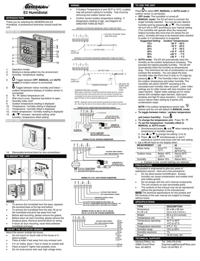
GeneralAire E2 Installation instructions

GeneralAire
GeneralAire GFX4 User manual