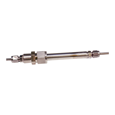
Geokon LVRA1230B User manual

Instruction Manual
Model 4675
Liquid Level Sensor
No part of this instruction manual may be reproduced, by any means, without the written consent of Geokon, Inc.
The information contained herein is believed to be accurate and reliable. However, Geokon, Inc. assumes no responsibility for
errors, omissions or misinterpretation. The information herein is subject to change without notification.
Copyright © 1995, 2006, 2008 by Geokon, Inc.
(Doc Rev F, 04/08)


Warranty Statement
Geokon, Inc. warrants its products to be free of defects in materials and workmanship, under normal use and
service for a period of 13 months from date of purchase. If the unit should malfunction, it must be returned to the
factory for evaluation, freight prepaid. Upon examination by Geokon, if the unit is found to be defective, it will
be repaired or replaced at no charge. However, the WARRANTY is VOID if the unit shows evidence of having
been tampered with or shows evidence of being damaged as a result of excessive corrosion or current, heat,
moisture or vibration, improper specification, misapplication, misuse or other operating conditions outside of
Geokon's control. Components which wear or which are damaged by misuse are not warranted. This includes
fuses and batteries.
Geokon manufactures scientific instruments whose misuse is potentially dangerous. The instruments are intended
to be installed and used only by qualified personnel. There are no warranties except as stated herein. There are no
other warranties, expressed or implied, including but not limited to the implied warranties of merchantability and
of fitness for a particular purpose. Geokon, Inc. is not responsible for any damages or losses caused to other
equipment, whether direct, indirect, incidental, special or consequential which the purchaser may experience as a
result of the installation or use of the product. The buyer's sole remedy for any breach of this agreement by
Geokon, Inc. or any breach of any warranty by Geokon, Inc. shall not exceed the purchase price paid by the
purchaser to Geokon, Inc. for the unit or units, or equipment directly affected by such breach. Under no
circumstances will Geokon reimburse the claimant for loss incurred in removing and/or reinstalling equipment.
Every precaution for accuracy has been taken in the preparation of manuals and/or software, however,
Geokon, Inc. neither assumes responsibility for any omissions or errors that may appear nor assumes
liability for any damages or losses that result from the use of the products in accordance with the
information contained in the manual or software.

TABLE of CONTENTS
1. INTRODUCTION AND THEORY OF OPERATION ...................................................................................1
2. INSTALLATION ................................................................................................................................................2
2.1 INSTALL THE MOUNTING BRACKETS .................................................................................................................2
2.2 ATTACHING THE FLUID LINES ...........................................................................................................................2
2.3 INSTALLING THE SENSORS................................................................................................................................3
2.4 THE NEXT STEP IS TO CONNECT THE TWO VENT LINES......................................................................................3
2.5 THE NEXT STEP IS TO FILL THE LIQUID LINE......................................................................................................3
2.6 THE CHAMBERS SHOULD NOW BE FILLED,.........................................................................................................4
3. CALIBRATION ..................................................................................................................................................4
4. TAKING READINGS.........................................................................................................................................4
5. CORRECTIONS FOR TEMPERATURE CHANGES...................................................................................6
6. TROUBLESHOOTING......................................................................................................................................7
7. SPECIFICATIONS.............................................................................................................................................7
APPENDIX A: THERMISTOR CHART............................................................................................................8
APPENDIX B: TYPICAL CALIBRATION SHEET...........................................................................................9

LIST of FIGURES, TABLES and EQUATIONS
FIGURE 1. MODEL 4675 LIQUID LEVEL SENSOR -PRINCIPLE OF OPERATION............................................................ 1
FIGURE 2. INSTALLATION DETAILS ........................................................................................................................... 2
FIGURE 3. DENSITY P OF PURE WATER AS A FUNCTION OF TEMPERATURE AND PRESSURE INTENSITY........................ 6
THERMISTOR LINEARIZATION USING STEINHART AND HART LOG EQUATION............................................................ 8
RESISTANCE VERSUS TEMPERATURE TABLE.............................................................................................................. 8


1
1. Introduction and Theory of Operation
The Model 4675 System is designed to detect and measure very small changes of elevation at discrete locations. It
has been used to measure differential settlements along tunnels, deflections of bridges and bridge piers, the
settlement of building columns and floor slabs etc., i.e. situations in which high accuracy and resolution are
essential.
A series of chambers, (vessels), are connected together by means of a liquid filled tube. One reference chamber is
located on stable ground or is at a point that can be surveyed to. The other chambers are located at the points
where settlement or heave is to be measured. Each chamber contains a cylindrical weight suspended from a
vibrating wire transducer. The common liquid level inside each chamber partially submerges the hanging weights
so that settlement or heave of at any one of the chamber locations causes an apparent rise or fall of the water level
in that chamber, leading to a greater or lesser buoyancy force on the weight and an decrease or increase of tension
and frequency of vibration in the vibrating wire.
A very high resolution/accuracy of the order of 0.07mm can be attained. A vent line connecting all the transducer
elements and the space above the liquid in each of the chambers reduces the effect on the readings caused by
changing temperatures and barometric fluctuations. It will be noted that the vibrating wire transducer is
measuring a force and thus is itself not subject to temperature effects. Temperature effects on the connecting
tubing and the liquid result in equal changes in water level in all the chambers and thus is cancelled out when the
data is reduced.
Readout of the instruments is accomplished with portable readouts such as the GK-403 or the GK-404 or one of
the Geokon data acquisition systems such as the Micro-10.
Figure 1. Model 4675 Liquid Level Sensor - Principle of Operation

2
2. Installation
Before any attempt is made to install the sensors the following directions must be read and understood.
The vibrating wire transducer is very sensitive and correspondingly fragile, and must be handled with great care.
Figure 2. Installation Details
2.1 Install the mounting brackets
The first step is to install the mounting brackets. It is important to install all chambers at about the same elevation
at the start of the monitoring program since the range of the transducer is limited and the amount of adjustment is
small.
The chamber mounting bracket is designed to be bolted to a wall or a pedestal and should be firmly attached with
either anchor bolts or epoxy grouted studs. The chamber assembly has three threaded supports, which allow for
precise leveling of the system. When all brackets have been installed, the chambers should be attached using the
three threaded rods and nuts supplied. Tighten one nut against the base of the chamber and use the other two nuts
one on either side of the bracket. Level by placing a spirit level on the chamber cylinder, and then adjust the level
with the nuts on the threaded rods that pass through the brackets. The unit must be within + / - 1.5 degrees of
vertical for proper operation. When the cylinder is level, tighten the nuts from both sides of the bracket.
2.2 Attaching the fluid lines
The next step is to attach the fluid lines. This is usually accomplished by running a large diameter pipe between
chambers and having T connections and ball valves at each chamber location. The interconnecting pipe must be
kept below the chambers and, if possible, be slightly inclined from one end to the other. The first chamber, at
the lowest end, uses the filling valve which has attached to it the valve for draining and filling. The chamber valve

3
below the last chamber has one side of the Tee plugged. The intermediate chambers use valves with barb
connectors on both sides.
2.3 Installing the sensors
THIS OPERATION IS VERY CRITICAL AND SHOULD BE PERFORMED WITH EXTREME CARE. A
spring and a stop protect the load sensor from over-range but severe dynamic shocks can destroy the vibrating
wire element.
2.3.1 The chambers are shipped fully assembled minus the hanging weights. Unscrew the three cap screws
holding the top cap to the chamber and gently pull the top cap and transducer from the top of the chamber.
2.3.2 The next step is to attach the cylindrical weight to the vibrating wire transducer and place the assembly
inside the chamber. THIS OPERATION REQUIRES EXTREME CARE.
Remember that the cylindrical weight serial number needs to match the transducer serial number: the serial
numbers will be found on the labels attached to the cylindrical weights and to the transducer housings and also on
the transducer cables.
Before installing the cylindrical weight, remove the orange colored spacer from the hook assembly. (This
releases the tension in the wire - a safety precaution which protects the sensor from damage during shipment)..
While holding the transducer housing with both hands, hook the weight onto the hook on the transducer and
gently lift the weight keeping the transducer housing vertical.
Lower the cylindrical weight into the chamber and hold the cap just above the chamber. Now, line up the holes in
the chamber with the screw holes in the cap. Gently lower the cap into the chamber being careful not to jar it as
the O-ring comes into contact with the tube. When the cap is all the way in place, put the three screws in and
tighten them. Do not over-tighten. Repeat this procedure for all the chambers.
2.4 The next step is to connect the two vent lines.
The purpose of the chamber vent line is to allow the air pressure above the fluid in all the chambers to
equilibrate. A separate transducer vent line for the transducer prevents any chamber liquid from accidentally
getting into the transducer. The two vent lines should be connected together at one end. The pipe plug on the
chamber vent line at the first chamber should be removed and left open until the filling process is completed.
2.5 The next step is to fill the liquid line.
The filling operation should be done very carefully to exclude air bubbles from the lines. The liquid can be either
water or antifreeze solution. If the latter then it is important that the calibration of the transducers be performed
using the same concentration of antifreeze as will be put into use. If water is used a small amount of antifreeze or
bleach should be added to prevent the growth of algae. The first step is to fill the liquid line from one end to the
other, while keeping the chamber valves closed. The filling reservoir supplied with the system should be filled
with liquid and should be connected using a short section of the supplied tubing and filling valve which is
connected to the chamber valve at the base of the first chamber (This first chamber should also be the lowest

4
chamber so that the liquid entering the fluid line flows uphill). Remove the plug from the chamber valve below
the last chamber, open the filling valve and allow the liquid to slowly fill the liquid line. When the liquid line is
full the plug at far end of the line can be replaced.
2.6 The chambers should now be filled,
to approximately mid-height on the weight. This is the recommended starting point. Start filling by opening the
valve on the chamber that is closest to the supply. Allow the liquid to come to approximately the 1/2 filled
position as viewed on the chamber site tube. The limits of the range are marked on the chamber site tube. Close
the valve. Go to the next chamber in line and repeat this operation.
When all the chambers have been filled to this level and closed off, go to the filling valve and close it. Now open
all of the chamber valves and allow the liquid level to equilibrate in all the chambers. If any chamber is seen to be
either to high or too low it should be adjusted now, using the threaded rod mounts if possible. If this is not
possible the mounting bracket may need to be moved. The system liquid level can now be adjusted by adding or
removing liquid through the filling valve. When the proper level is achieved the valve is closed and the supply
reservoir can be disconnected. To prevent tampering with the liquid level the handle should be removed form the
filling valve. The plug on the end of the chamber vent line at the first chamber can now be replaced. The
desiccant chamber can be attached to the open end of the transducer vent line. The sensor operation should be
confirmed now by taking readings on all sensors and calculating the submersion of each sensor. This is
accomplished by taking the change in output of the gage from the zero reading, (R0) with the weight hanging in
air, and the current reading with the weight submerged and multiplying by the gage factor. The gage factor and
zero reading, (R0) are shown on the calibration sheets. (See Appendix B, Page 10). The result should match,
approximately, the position of the water in the sight tube on the chamber.
3. Calibration
Laboratory calibrations are performed on each individual sensor using a system of calibrated weights. Gage
factors are presented for pure water applications. If mixtures other than this are used, the gage factor should be
adjusted for the specific gravity of the fluid used.
4. Taking Readings
The Model 4675 is read using the GK-401, GK-403 or GK-404 Readout Box in Position ‘B’.
The change in elevation for any particular chamber in a system is determined as follows:
∆ELx = (R1x– R0x ) Gx– (R1Ref – R0Ref ) G Ref
where: ∆ELx= Change in Elevation for Chamber x
R1x= Current Reading Chamber x
R
0x= Initial Reading Chamber x
G
x= Calibration Factor Chamber x

5
R
0Ref = Initial Reading Reference Chamber
R
1Ref = Current Reading Reference Chamber
G
Ref = Calibration Factor Reference Chamber
Note: Negative values of ∆ELxindicate settlement. (Positive values of ∆ELxindicated heave).
Example: The initial readings on a 4 chamber system (3 active and reference chamber) are as follows:
Chamber Reading Calibration Factor
1 (Ref) 7163 0.002852
2 7858 0.002856
3 7967 0.002808
4 8028 0.002852
Subsequent readings on the chambers are as follows:
Chamber Reading
1 (Ref) 7118
2 7813
3 8628
4 7637
The changes in elevation of Chambers 2, 3 and 4 are:
a) Chamber No. 2: ∆EL2= (R12– R02) G2– (R11– R01) G1
= (7813 – 7858) 0.002856 – (7118 – 7163) 0.002852
= – 0.1285 – (– 0.1283)
= – 0.0002″(No Movement)
b) Chamber No. 3: ∆EL3= (R13– R03) G3 – (R11– R01) G1
= (8628 – 7967) 0.002808 – (7118 – 7163) 0.002852
= 1.8561 – (– 0.1283)
= 1.9843″(Heave)
c) Chamber No. 4: ∆EL4= (R14– R04) G4– (R11– R01) G1
= (7637 – 8028) 0.002852 – (7118 – 7163) 0.002852
= – 1.1151 – (– 0.1283)
= – 0.9868″(Settlement)

6
5. Corrections for Temperature Changes
The vibrating wire sensor itself is insensitive to temperature changes within the normal operating range. The
system, however, is not entirely unaffected by changes in water temperature which influence the density and
therefore, the buoyancy of the fluid. The influence is relatively minor and can be accounted for to some degree
by measuring the water temperature and making density corrections. A temperature/density curve for water is
shown in Figure 2. As can be seen from the data, the density changes very little in the normal operating range of
the sensor. The following equation is used to correct for temperature/density changes:
∆H = (R1– R0) G / (SG)
where: SG is the specific gravity of the fluid (water) at the measurement temperature
Density and Compressibility
Density is defined as the mass per unit volume, and it depends upon the temperature and pressure intensity.
The density of pure water is given in Figure 3.
Figure 3. Density p of pure water as a function of temperature and pressure intensity. By
permission from Fluid Mechanics for Hydraulic Engineers, by Hunter Rouse, copyright 1938, McGraw-Hill
Book Company, Inc.
Expansion and contraction of the liquid line, the liquid itself and the chambers can cause the water level to
fluctuate. However, the fluctuations are the same at all chambers and cancel out on data reduction.

7
6. Troubleshooting
If a transducer fails to read, the following steps should be taken
1. Check the coil resistance. Nominal coil resistance is 180Ω±10 plus cable resistance
(22 gage copper = approximately 20Ωper 1000 feet).
a) If the resistance is high or infinite, a cut cable must be suspected.
b) If the resistance is low or near zero, a short must be suspected.
c) If resistances are within nominal and no readings are obtainable on any transducer, the readout is
suspect
and the factory should be consulted.
d) If all resistances are within nominal and no readings are obtainable on any transducer, the readout is
suspect and the factory should be consulted.
2. If cuts or shorts are located, the cable may be splices in accordance with recommended procedures.
7. Specifications
Standard ranges 150, 300, 600 mm
Resolution 0.07, 0.07, 0.15mm
System accuracy ±0.1 to ±0.4mm
Temperature Range -20ºC to +80ºC
Frequency Range 1400-3500Hz

8
Appendix A: Thermistor Chart
Thermistor Linearization using Steinhart and Hart Log Equation
Tech Memo 91-03 Doc Rev 6-94, Geokon, Inc.
Thermistor Type: YSI 44005, Dale #1C3001-B3, Alpha #13A3001-B3
Basic Equation: TA B LnR C LnR
=
++
−
1273 2
3
()() .
where: T=Temperature in °C.
LnR =Natural Log of Thermistor Resistance
A=1.4051 ×10⁻³
B=2.369 ×10⁻⁴
C=1.019 ×10⁻⁷
Note: Coefficients calculated over -50
°
to +150
°
C. span.
Resistance versus Temperature Table
Ohms Temp Ohms Temp Ohms Temp Ohms Temp Ohms Temp
201.1K -50 16.60K -10 2417 +30 525.4 +70 153.2 +110
187.3K -49 15.72K -9 2317 31 507.8 71 149.0 111
174.5K -48 14.90K -8 2221 32 490.9 72 145.0 112
162.7K -47 14.12K -7 2130 33 474.7 73 141.1 113
151.7K -46 13.39K -6 2042 34 459.0 74 137.2 114
141.6K -45 12.70K -5 1959 35 444.0 75 133.6 115
132.2K -44 12.05K -4 1880 36 429.5 76 130.0 116
123.5K -43 11.44K -3 1805 37 415.6 77 126.5 117
115.4K -42 10.86K -2 1733 38 402.2 78 123.2 118
107.9K -41 10.31K -1 1664 39 389.3 79 119.9 119
101.0K -40 9796 0 1598 40 376.9 80 116.8 120
94.48K -39 9310 +1 1535 41 364.9 81 113.8 121
88.46K -38 8851 2 1475 42 353.4 82 110.8 122
82.87K -37 8417 3 1418 43 342.2 83 107.9 123
77.66K -36 8006 4 1363 44 331.5 84 105.2 124
72.81K -35 7618 5 1310 45 321.2 85 102.5 125
68.30K -34 7252 6 1260 46 311.3 86 99.9 126
64.09K -33 6905 7 1212 47 301.7 87 97.3 127
60.17K -32 6576 8 1167 48 292.4 88 94.9 128
56.51K -31 6265 9 1123 49 283.5 89 92.5 129
53.10K -30 5971 10 1081 50 274.9 90 90.2 130
49.91K -29 5692 11 1040 51 266.6 91 87.9 131
46.94K -28 5427 12 1002 52 258.6 92 85.7 132
44.16K -27 5177 13 965.0 53 250.9 93 83.6 133
41.56K -26 4939 14 929.6 54 243.4 94 81.6 134
39.13K -25 4714 15 895.8 55 236.2 95 79.6 135
36.86K -24 4500 16 863.3 56 229.3 96 77.6 136
34.73K -23 4297 17 832.2 57 222.6 97 75.8 137
32.74K -22 4105 18 802.3 58 216.1 98 73.9 138
30.87K -21 3922 19 773.7 59 209.8 99 72.2 139
29.13K -20 3748 20 746.3 60 203.8 100 70.4 140
27.49K -19 3583 21 719.9 61 197.9 101 68.8 141
25.95K -18 3426 22 694.7 62 192.2 102 67.1 142
24.51K -17 3277 23 670.4 63 186.8 103 65.5 143
23.16K -16 3135 24 647.1 64 181.5 104 64.0 144
21.89K -15 3000 25 624.7 65 176.4 105 62.5 145
20.70K -14 2872 26 603.3 66 171.4 106 61.1 146
19.58K -13 2750 27 582.6 67 166.7 107 59.6 147
18.52K -12 2633 28 562.8 68 162.0 108 58.3 148
17.53K -11 2523 29 543.7 69 157.6 109 56.8 149
55.6 150

9
Appendix B: Typical Calibration Sheet
S
ample Calibration shee
t
.
N
ote that the Volume Facto
r
,
K
,
is used to convert the Calibration
f
actor
,
C
,
into the Calibration Factor
,
G.
Table of contents
Other Geokon Accessories manuals

Geokon
Geokon 4000 Series User manual

Geokon
Geokon 4500HT-9-5 Manual

Geokon
Geokon 6160 User manual

Geokon
Geokon 6160 User manual

Geokon
Geokon 4600 User manual

Geokon
Geokon 6160 User manual

Geokon
Geokon 4600 User manual

Geokon
Geokon 4100 Series User manual

Geokon
Geokon RB-500 User manual

Geokon
Geokon 4900 User manual