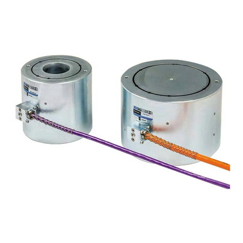
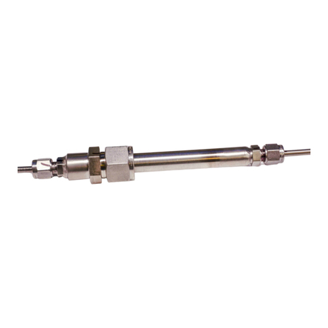
Geokon 4100 Series User manual

©2021, GEOKON. All rights reserved.
Document Revision: HH | Release date: 04/12/21
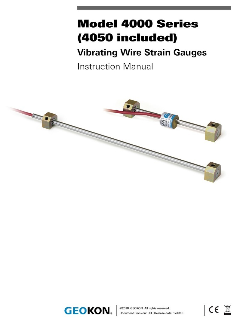
Model 4100/4150 Series
Vibrating Wire Strain Gauges
Instruction Manual


WARRANTY STATEMENT
GEOKON warrants its products to be free of defects in materials and workmanship,
under normal use and service for a period of 13 months from date of purchase. If the
unit should malfunction, it must be returned to the factory for evaluation, freight
prepaid. Upon examination by GEOKON, if the unit is found to be defective, it will be
repaired or replaced at no charge. However, the WARRANTY IS VOID if the unit shows
evidence of having been tampered with or shows evidence of being damaged as a
result of excessive corrosion or current, heat, moisture or vibration, improper specifi-
cation, misapplication, misuse or other operating conditions outside of GEOKON's
control. Components that wear or are damaged by misuse are not warranted. This
includes fuses and batteries.
GEOKON manufactures scientific instruments whose misuse is potentially dangerous.
The instruments are intended to be installed and used only by qualified personnel.
There are no warranties except as stated herein. There are no other warranties,
expressed or implied, including but not limited to the implied warranties of merchant-
ability and of fitness for a particular purpose. GEOKON is not responsible for any
damages or losses caused to other equipment, whether direct, indirect, incidental,
special or consequential which the purchaser may experience as a result of the instal-
lation or use of the product. The buyer's sole remedy for any breach of this agreement
by GEOKON or any breach of any warranty by GEOKON shall not exceed the purchase
price paid by the purchaser to GEOKON for the unit or units, or equipment directly
affected by such breach. Under no circumstances will GEOKON reimburse the
claimant for loss incurred in removing and/or reinstalling equipment.
Every precaution for accuracy has been taken in the preparation of manuals and/or
software, however, GEOKON neither assumes responsibility for any omissions or
errors that may appear nor assumes liability for any damages or losses that result
from the use of the products in accordance with the information contained in the
manual or software.
No part of this instruction manual may be reproduced, by any means, without the written consent of GEOKON. The
information contained herein is believed to be accurate and reliable. However, GEOKON assumes no responsibility
for errors, omissions or misinterpretation. The information herein is subject to change without notification.
The GEOKON® wordmark and logo are registered trademarks with the United States Patent and Trademark Office.


I
TABLE OF CONTENTS
1. INTRODUCTION............................................................................................................................................1
2. PRELIMINARY CHECKS......................................................................................................................3
2.1 USING A READOUT............................................................................................................................3
2.2 USING AN OHMMETER..................................................................................................................3
3. INSTRUMENT PROTECTION.........................................................................................................4
3.1 CABLE SPLICING AND TERMINATION............................................................................4
3.2 PROTECTION FROM MECHANICAL DAMAGE...........................................................4
3.2.1 SECURING CABLES..........................................................................................................................4
3.2.2 COVER PLATES ..................................................................................................................................4
3.3 CABLE AND CONNECTOR PROTECTION........................................................................6
3.4 PROTECTION FROM CORROSION........................................................................................6
3.5 PROTECTION FROM ELECTRICAL NOISE......................................................................7
3.6 PROTECTION FROM SUNLIGHT AND TEMPERATURE CHANGES .........7
3.7 LIGHTNING PROTECTION............................................................................................................7
4. GAUGE INSTALLATION.......................................................................................................................9
4.1 ADJUSTING THE GAUGE WIRE TENSION ....................................................................9
4.2 INSTALLING THE 4100/4150 VIA SPOT WELDING .............................................9
4.2.1 PREPARE THE SURFACE................................................................................................................9
4.2.2 SPOT WELD TEST STRIPS .............................................................................................................9
4.2.3 SPOT WELDING THE 4100 GAUGE ....................................................................................... 10
4.2.4 SPOT WELDING THE 4150 GAUGE ....................................................................................... 10
4.2.5 WELDING THE SECOND END PIECE..................................................................................... 11
4.2.6 INSTALLING COLLAR SHIMS................................................................................................... 11
4.2.7 INSTALLING THE PLUCKING COIL HOUSING (MODEL 4100 ONLY) ...................... 13
4.2.8 INSTALLING THE GAUGE COVER (MODEL 4150 ONLY).............................................. 13
4.2.9 SECURING THE 4150 GAUGE CABLE................................................................................... 13
4.3 INSTALLING THE 4100/4150 VIA EPOXY BONDING...................................... 13
4.4 INSTALLING THE 4151 STRAIN GAUGE.................................................................... 15
5. GAUGE LOCATION ................................................................................................................................16
5.1 END EFFECTS...................................................................................................................................... 16
5.2 WELDING EFFECTS........................................................................................................................ 16
5.3 BENDING MOMENTS................................................................................................................... 16
6. TAKING READINGS ............................................................................................................................. 20
6.1 STRAIN GAUGE READOUT POSITIONS ...................................................................... 20
II
6.2 GK-404 VIBRATING WIRE READOUT ............................................................................ 20
6.2.1 OPERATING THE GK-404............................................................................................................ 20

6.3 GK-405 VIBRATING WIRE READOUT ............................................................................ 21
6.3.1 CONNECTING SENSORS WITH 10-PIN BULKHEAD CONNECTORS
ATTACHED........................................................................................................................................ 21
6.3.2 CONNECTING SENSORS WITH BARE LEADS ................................................................... 21
6.3.3 OPERATING THE GK-405............................................................................................................ 21
6.4 MEASURING TEMPERATURES............................................................................................ 22
7. DATA REDUCTION................................................................................................................................. 23
7.1 CONVERSION OF THE READINGS TO STRAIN CHANGES ......................... 23
7.2 CONVERTING STRAINS TO STRESSES....................................................................... 23
8. TROUBLESHOOTING........................................................................................................................... 24
APPENDIX A. SPECIFICATIONS................................................................................................... 25
A.1 VIBRATING WIRE STRAIN GAUGE.................................................................................. 25
A.2 THERMISTOR ...................................................................................................................................... 25
APPENDIX B. THEORY OF OPERATION .............................................................................. 26
APPENDIX C. THERMISTOR TEMPERATURE DERIVATION ....................... 28
C.1 3KΩ THERMISTOR RESISTANCE...................................................................................... 28
C.2 10KΩ THERMISTOR RESISTANCE .................................................................................. 29
APPENDIX D. TEMPERATURE CORRECTION WHEN USED ON
CONCRETE..................................................................................................................... 30
APPENDIX E. TEMPERATURE EFFECTS............................................................................. 31
APPENDIX F. CALCULATIONS FROM THREE STRAIN GAUGES,
AT 60 DEGREES, ON A CIRCULAR PIPE ................................... 32
APPENDIX G. MODEL 4150-5 EXTENDED RANGE STRAIN GAUGE 33
APPENDIX H. PARTS LIST.................................................................................................................. 34

III
FIGURES
FIGURE 1: MODEL 4100 VIBRATING WIRE STRAIN GAUGE .........................................1
FIGURE 2: MODEL 4150 VIBRATING WIRE STRAIN GAUGE .........................................2
FIGURE 3: MODEL 4151 VIBRATING WIRE STRAIN GAUGE .........................................2
FIGURE 4: MODEL 4100 COVER PLATE - TOP VIEW ......................................................5
FIGURE 5: MODEL 4150 COVER PLATE - TOP VIEW ......................................................5
FIGURE 6: COVER PLATE - END VIEW ............................................................................5
FIGURE 7: COVER PLATE INSTALLATION, TOP VIEW ....................................................6
FIGURE 8: COVER PLATE INSTALLATION, SIDE VIEW ...................................................6
FIGURE 9: LIGHTNING PROTECTION SCHEME ...............................................................8
FIGURE 10: PEEL TEST ....................................................................................................10
FIGURE 11: SPOT-WELDING SEQUENCE, OUTER ROWS (4100) ................................10
FIGURE 12: SPOT WELDING SEQUENCE, OUTER ROWS (4150) ................................10
FIGURE 13: SPOT WELDING SEQUENCE, INNER ROWS ............................................11
FIGURE 14: USING THE ALIGNMENT TOOL ..................................................................11
FIGURE 15: COLLAR SHIM .............................................................................................12
FIGURE 16: WELDING THE COLLAR SHIM IN PLACE ..................................................12
FIGURE 17: COMPLETED COLLAR SHIM ......................................................................12
FIGURE 18: SPOT WELDED COVER PLATE ...................................................................13
FIGURE 19: MODEL 4151 STRAIN GAUGE INSTALLATION .........................................15
FIGURE 20: STRAIN GAUGES MOUNTED ON CENTRAL WEB ....................................16
FIGURE 21: STRAIN GAUGES MOUNTED ON FLANGES .............................................18
FIGURE 22: AXIAL STRAIN MEASUREMENT/BENDING MOMENT ABOUT YY AXIS .18
FIGURE 23: AXIAL STRAIN AND BENDING MOMENT ABOUT XX AXIS ....................19
FIGURE 24: AXIAL STRAIN AND BENDING MOMENT ABOUT AXIS XX (NOT
RECOMMENDED) ........................................................................................19
FIGURE 25: GK-404 READOUT .......................................................................................20
FIGURE 26: LEMO CONNECTOR TO GK-404 .................................................................20
FIGURE 27: GK-405 READOUT .......................................................................................21
FIGURE 28: GAUGE ASSEMBLY DIMENSIONS .............................................................25
FIGURE 29: COVER ASSEMBLY DIMENSIONS .............................................................25
FIGURE 30: THREE STRAIN GAUGES MOUNTED ON A CIRCULAR PIPE ...................32

IV
TABLES
TABLE 1: GUIDE TO INITIAL TENSION SETTINGS ............................................................9
TABLE 2: STRAIN GAUGE READOUT POSITIONS...........................................................20
TABLE 3: SPECIFICATIONS ...............................................................................................25
TABLE 4: 3KΩ THERMISTOR RESISTANCE .....................................................................28
TABLE 5: 10KΩ THERMISTOR RESISTANCE ...................................................................29
TABLE 6: MODEL 4100/4150 SERIES MODEL AND PARTS LIST..................................34

V
EQUATIONS
EQUATION 1: AXIAL STRESS CALCULATION................................................................. 17
EQUATION 2: STRESS DUE TO BENDING ON AXIS YY ................................................. 17
EQUATION 3: STRESS DUE TO BENDING ON AXIS XX................................................. 17
EQUATION 4: MAXIMUM STRESS .................................................................................. 17
EQUATION 5: THEORETICAL MICROSTRAIN ................................................................. 23
EQUATION 6: STRAIN CALCULATION............................................................................. 23
EQUATION 7: 3KΩ THERMISTOR RESISTANCE............................................................. 28
EQUATION 8: 10KΩ THERMISTOR RESISTANCE........................................................... 29
EQUATION 9: THERMAL CONCRETE STRAINS.............................................................. 30
EQUATION 10: ACTUAL STRAIN ..................................................................................... 30
EQUATION 11: STRAIN DUE TO LOAD CHANGES ONLY ............................................. 30
EQUATION 12: EXTERNAL LOAD STRESS ONLY........................................................... 31
EQUATION 13: FREE FIELD THERMAL STRAINS .......................................................... 31
EQUATION 14: ACTUAL STRAIN ..................................................................................... 31
EQUATION 15: AVERAGE AXIAL STRAIN ....................................................................... 32
EQUATION 16: MAXIMUM BENDING STRAIN AROUND THE YY AXIS ...................... 32
EQUATION 17: MAXIMUM BENDING STRAIN AROUND THE XX AXIS ...................... 32
EQUATION 18: MAXIMUM STRAIN ................................................................................ 32
EQUATION 19: MODEL 4150-5 TEMPERATURE EFFECTS ........................................... 33

VI

MODEL 4100/4150 SERIES VIBRATING WIRE STRAIN GAUGES | INTRODUCTION | 1
1. INTRODUCTION
GEOKON’s 4100/4150 Series Vibrating Wire Strain Gauges are intended primarily
for measuring strain on structural steel members, such as tunnel linings, arches,
struts, piles, sheet piling, etc.
■Model 4100 consists of a vibrating wire gage element and removable coil
assembly.
■Model 4150 consists of a vibrating wire gage element and integral coil
assembly. (Also available is Model 4150-5, which has a range of 10,000
microstrains. See Appendix G for more information.)
■Model 4151 is a modification of the 4150 strain gauge, in which the spot-
weldable tabs have been replaced by pins welded to the end blocks. These
are designed to be grouted into holes drilled into the material under test.
Versions of Model 4151 are available with extended ranges. These gauges
are useful for measurements in high strain regimes such as on plastic pipes
or piles and on fiberglass structural members and rebars. Their small size
makes them particularly suitable where space and or access is limited.
The primary means of attaching the Model 4100/4150 strain gauges to steel
members is spot-welding, but they may also be epoxy bonded to the surface
(see Section 4.3).
Strain is measured using the vibrating wire principle. A length of steel wire is
tensioned between two end points that are welded to the steel surface being
studied. Deformations of the surface will cause the two end points to move in
relation to each other, altering the tension in the steel wire. This change in
tension is measured as a change in the wire’s resonant frequency of vibration.
Two coils, one with a magnet insert and the other with a pole piece insert, are
located close to the vibrating wire. Applying a pulse of varying frequency (swept
frequency) to the coils causes the wire to vibrate primarily at its resonant
frequency.
Portable readouts and dataloggers are available from GEOKON. These devices,
when used with vibrating wire strain gauges, provide the necessary voltage
pulses to pluck the wire. During vibration, a sinusoidal signal is induced in the
coils and transmitted to the readout box where it is conditioned and displayed.
This manual contains installation instructions, readout instructions,
recommended maintenance, and troubleshooting procedures. The theory of the
gauge is also provided, along with some suggestions for data interpretation.
1:
FIGURE 1: Model 4100 Vibrating Wire Strain Gauge
Mounting
Tab End Block
Protective
Tube Tension Nut Spring

2| INTRODUCTION | GEOKON
2:
FIGURE 2: Model 4150 Vibrating Wire Strain Gauge
3:
FIGURE 3: Model 4151 Vibrating Wire Strain Gauge
Mounting Tab End Block Protective Tube
Tension Nut
Spring
Green Wire
White Wire
Coil Assembly
Red Wire
Black Wire
Instrument cable (4 conductor, 2 AWG)
Thermistor
End Block Protective Tube Tension NutCoil Assembly
Pin
Spring
Green Wire
White Wire
Red Wire
Black Wire
Instrument cable (4 conductor, 2 AWG)
Thermistor
Pin

MODEL 4100/4150 SERIES VIBRATING WIRE STRAIN GAUGES | PRELIMINARY CHECKS | 3
2. PRELIMINARY CHECKS
2.1 USING A READOUT
Perform a preliminary check before installing the gauge in the field. To perform
the preliminary check, complete the following steps:
1. Insert the gauge into the underside of the coil assembly (4100 only).
2. Connect the gauge leads to a readout box. See Section 6 in necessary.
3. Observe the displayed readout. The reading should be around the midrange
position as defined in Section 6. The temperature reading should match the
ambient temperature.
Note: Strain gauges are supplied with the wire tension set near midrange;
this gives enough range in both tension and compression to be suitable for
most applications. If adjustment to the strain range is necessary, see
Section 4.1. Under no circumstances should the procedures
described in Section 4.1 be used after the gauge has been welded
down.
4. Gently pull on the gauge end points; confirm that numbers on the readout
rise as the tension increases. Do not apply excessive tension (greater
than 10 Kgm / 20 lb.), as this may break the vibrating wire!
2.2 USING AN OHMMETER
If a readout is not available, the preliminary checks can be done using an
ohmmeter, as follows:
1. Check electrical continuity using the ohmmeter. Resistance between the
gauge leads (usually red and black) should be approximately 180 ohms (50
ohms for model 4150 series gauges.)
Note: Be sure to add cable resistance, which is approximately 14.7Ωper
1000 feet (48.5Ωper km) of 22 AWG stranded copper leads at 20 °C.
Multiply this factor by two to account for both directions.
2. Resistance between thermistor leads (usually green and white) will vary
based on temperature; refer to Appendix C. Resistance between any
conductor and the shield should exceed two megohms.
Should any of these preliminary tests fail, see Section 8 for troubleshooting tips.

4| INSTRUMENT PROTECTION | GEOKON
3. INSTRUMENT PROTECTION
3.1 CABLE SPLICING AND TERMINATION
Terminal boxes with sealed cable entries are available from GEOKON for all types
of applications. These allow many instruments to be terminated at one location
with complete protection of the lead wires. The interior panel of the terminal box
can have built-in jacks or a single connection with a rotary position selector
switch. Contact GEOKON for specific application information.
Because the vibrating wire output signal is a frequency rather than a current or
voltage, variations in cable resistance have little effect on instrument readings;
therefore, splicing of cables has no ill effects, and in some cases may in fact be
beneficial. The cable used for making splices should be a high quality twisted
pair type, with 100% shielding and an integral shield drain wire. When splicing,
it is very important that the shield drain wires be spliced together.
Always maintain polarity by connecting color to color.
Splice kits recommended by GEOKON incorporate casts that are placed around
the splice and are then filled with epoxy to waterproof the connections. When
properly made, this type of splice is equal or superior to the cable in strength
and electrical properties. Contact GEOKON for splicing materials and additional
cable splicing instructions.
Terminate a cable by stripping and tinning the individual conductors and then
connecting them to the patch cord of a readout box. Alternatively, use a
connector to plug directly into the readout box or to a receptacle on a special
patch cord.
3.2 PROTECTION FROM MECHANICAL DAMAGE
The cover of the 4100 coil housing provides a measure of protection for the
strain gauge, which is adequate in most cases. In extreme environments and/or
where long term performance is required, gauge and lead wires may require
additional protection from corrosion and mechanical damage.
3.2.1 SECURING CABLES
Cables should be adequately restrained so that there is no danger of the coil
housing being damaged (Model 4100) or the lead wires torn out (Model 4150) by
tugging on the cable. Cables may be secured using pieces of stainless steel shim
strips (supplied), spot welded in place over the top of the cable. Tie wraps, tape,
or wire ties may also be used to secure the gauge cables.
3.2.2 COVER PLATES
Gauges can be further protected by welding cover plates composed of 101 x 38
mm (4" x 1.5") channel iron or 64 mm (2.5") or larger angle iron over the top of
the gauges.
To avoid damaging the cables, the protection should be welded on before the
gauges and cables are installed. To accomplish this, leave windows in the steel
over the gauge locations.
Note: It is not necessary to use continuous welds; tack welding is sufficient as
long as it holds the angles or channels firmly in place. Cables must be restrained
using welding studs, to which the cables can be tied at three-meter intervals.

MODEL 4100/4150 SERIES VIBRATING WIRE STRAIN GAUGES | INSTRUMENT PROTECTION | 5
4:
FIGURE 4: Model 4100 Cover Plate - Top View
5:
FIGURE 5: Model 4150 Cover Plate - Top View
6:
FIGURE 6: Cover Plate - End View
INSTALL THE COVER PLATES AS FOLLOWS:
1. Weld the two 9.5 x 51 mm (3/8 x 2") long hex bolts in place head down. The
bolts should be spaced at a nominal 530 mm (21") apart. A spacer jig is
available from GEOKON, or the cover plate can be flipped onto its back and
the holes in the cover plate can be used to mark the bolt locations. One hole
in the cover plate is slotted, so the spacing is not critical. Avoid welding
anywhere near the gauge as this will cause large local distortions in the
metal. Use either a special stud welder or an arc welder to weld the head of
the bolt to the surface.

6| INSTRUMENT PROTECTION | GEOKON
2. Place the cover plate over the welded bolts.
3. Install washers, then nuts. Avoid excessive force while tightening the cover
retaining nuts, as this will distort the underlying steel surface and can give
rise to spurious strain readings.
7:
FIGURE 7: Cover Plate Installation, Top View
8:
FIGURE 8: Cover Plate Installation, Side View
3.3 CABLE AND CONNECTOR PROTECTION
The cable should be protected from accidental damage caused by moving
equipment or fly rock. This is best accomplished by putting the cable inside
flexible conduit and positioning the conduit in as safe a place as possible.
(Flexible conduit is available from GEOKON.) The conduit can be connected via
conduit bulkhead connectors to the cover plates. (The GEOKON cover plate has a
stamped knockout which, when removed, provides a hole for connecting the
conduit connector.)
3.4 PROTECTION FROM CORROSION
It is imperative that installation weld points, if any, be protected from corrosion.
Stainless steel instruments will not corrode, but the substrate can corrode,
especially at weld points, unless they are covered by a waterproofing layer.
GEOKON recommends you follow this procedure:
1. Apply several drops of cyanoacrylate adhesive to the edge of all spot
welded mounting tabs. The glue will wick into the gap between the
mounting tabs and the substrate and provide the first line of defense.
2. Mask off the areas where spot welds are needed.
3. Spray self-etching primer (available locally) over mounting tab areas and all
exposed bare metal areas. The idea is to protect substrate weld points. It is
important to completely cover mounting tab edges, paying attention to
where the tab is under the instrument. Be sure to spray beneath the coil
housing, if applicable; do not worry if the primer also coats the instrument.

MODEL 4100/4150 SERIES VIBRATING WIRE STRAIN GAUGES | INSTRUMENT PROTECTION | 7
4. Apply a coat of paint over the primed areas.
In severe environments and for long term protection, the space between the coil
housing and the Model 4100 gauge, and the space between the cover plate and
the Model 4150 gauge, can be filled with a stiff grease (e.g., axle grease). For
further protection, the entire assembly can be covered by a layer of insulating
mastic (e.g. Plymouth 10 Plyseal), which is available from GEOKON.
3.5 PROTECTION FROM ELECTRICAL NOISE
Be sure to install instrument cables as far away as possible from sources of
electrical interference such as power lines, generators, motors, transformers, arc
welders, etc. Cables should never be buried or run with AC power lines. Doing
so will cause the instrument cables to pick up the frequency noise from the
power cable, and this will likely make obtaining a stable reading difficult.
3.6 PROTECTION FROM SUNLIGHT AND TEMPERATURE CHANGES
If attached to a steel structure, the thermal coefficient of expansion of the steel
vibrating wire inside the instrument is the same as that for the structure. This
means that no temperature correction for the measured strain is required when
calculating load-induced strains. However, this is only true if the wire and the
underlying steel structure are at the same temperature. If sunlight is allowed to
impinge directly onto the gauge, it could elevate the temperature of the wire
above the surrounding steel and cause large changes in apparent strain.
Therefore, always shield strain gauges from direct sunlight. Protection from
thermal effects is best provided by covering the gauges with a layer of insulating
material such as Polystyrene foam or fiberglass.
3.7 LIGHTNING PROTECTION
Unlike numerous other types of instrumentation available from GEOKON,
vibrating wire strain instruments do not have any integral lightning protection
components, such as transorbs or plasma surge arrestors.
SUGGESTED LIGHTNING PROTECTION OPTIONS:
■Lighting arrestor boards and enclosures are available from GEOKON. These
units install where the instrument cable exits the structure being monitored.
The enclosure has a removable top to allow the customer to service the
components or replace the board in the event that the unit is damaged by a
lightning strike. A connection is made between the enclosure and earth
ground to facilitate the passing of transients away from the instruments.
See the figure below.
■Plasma surge arrestors can be epoxied into the instrument cable, close to
the instrument. A ground strap then connects the surge arrestor to an earth
ground, such as a grounding stake or the steel structure.
Consult the factory for additional information on available lightning protection.

8| INSTRUMENT PROTECTION | GEOKON
9:
FIGURE 9: Lightning Protection Scheme

MODEL 4100/4150 SERIES VIBRATING WIRE STRAIN GAUGES | GAUGE INSTALLATION | 9
4. GAUGE INSTALLATION
4.1 ADJUSTING THE GAUGE WIRE TENSION
WARNING! Under no circumstances should the gauge tension be adjusted
after the gauge has been welded down.
Gauges are supplied with an initial reading of approximately 2500 microstrains.
This gives a range of ±1500 microstrains. This range is usually adequate for
most purposes and should not be altered except in unusual circumstances.
If the strain directions are known, the wire tension can be adjusted for greater
range in either compression or tension by completing the following:
1. Attach the red and black leads to a readout box which has been set to
position E.
2. Keep the gauge still by grasping the 4100 gauge by the tube, or the 4150
series gauges by the coil assembly.
3. Using a mini wrench, rotate the tensioning nut. The position of the nut
controls the spring tension. To increase the range of measurement to
accommodate more compressive strain, turn the nut in a clockwise
direction and set the initial reading to between 2500 and 3000 microstrains.
To increase the range of measurement for tensile strains rotate the nut in a
counterclockwise direction, setting the initial reading to between 1500 and
2000. A rotation of 1/2 turn will give a change of about 600 microstrains.
Table 1 details various tension settings.
1:
TABLE 1: Guide to Initial Tension Settings
4. The gauge end piece will often turn with the tensioning nut. After the
adjustment is made the end piece should be rotated back to its original
position so that the flats of the two end pieces are aligned. Again, hold the
tube/coil assembly while doing this.
5. Check the reading. If okay, apply a drop of thread locking cement to
preserve the nut position and the tension.
4.2 INSTALLING THE 4100/4150 VIA SPOT WELDING
CAUTION! Wear safety glasses while performing the following tasks.
4.2.1 PREPARE THE SURFACE
The surface of the steel member should be flat, clean, and free from rust, grease,
and pitting. Degrease the surface using an appropriate cleaning agent, then use
a power grinder or sander, file, wire brush or sandpaper, to achieve a flat,
smooth surface.
4.2.2 SPOT WELD TEST STRIPS
Before welding, it is necessary to test the spot welder to make sure that the
correct weld energy is being used. Weld energy, and to a certain extent, contact
pressure, determines the quality of the weld. Approximately 20 to 40 watt-
seconds of weld energy is required to properly weld 4100 or 4150 strain gauges
to structural steel.
Available Microstrain Range
Setting Range Microstrain Reading Tension Compression
Midrange 2500 1500 1500
Tension (67% of range) 2000 2000 1000
Compression (67% of range) 3000 1000 2000

10 | GAUGE INSTALLATION | GEOKON
Using the test material provided with the gauges, run a series of tests to
determine the correct weld energy. When the correct weld energy is used, the
test strip will show a series of holes where the welded strip has been left behind
on the substrate when peeled back from the steel surface with pliers, as shown
below.
10:
FIGURE 10: Peel Test
If insufficient weld energy is used, the test strip will pull loose without holes
being torn in it. If excessive weld energy is used, the test strip will discolor, melt,
and be ejected away from the spot. Sparking is usually an indication of dirt
between the test strip and the substrate. It may also be an indication of
insufficient force, in which case the force setting of the hand probe should be
adjusted. Excessive deformation of the weld area calls for either a decrease of
the force applied by the hand probe and/or a decrease of weld energy.
4.2.3 SPOT WELDING THE 4100 GAUGE
Spot weld one end of the gauge by placing a weld point at each of the marked
dots on the mounting tab, in the sequence shown below. Once that is complete,
weld the second mounting tab using instructions in Section 4.2.5.
11:
FIGURE 11: Spot Welding Sequence, Outer Rows
4.2.4 SPOT WELDING THE 4150 GAUGE
Spot weld the end of the gauge where the cable comes out by placing a weld
point at each of the marked dots on the mounting tab in the sequence shown
below. Carefully move the lead wires out of the way before beginning.
12:
FIGURE 12: Spot welding Sequence, Outer Rows
Test Holes Test Strip
Strip Material
Substrate
Start
1
2
3
4
Start
1
2
3
4
This manual suits for next models
6
Table of contents
Other Geokon Accessories manuals

Geokon
Geokon 6160 User manual

Geokon
Geokon 4600 User manual

Geokon
Geokon 6160 User manual

Geokon
Geokon 6160 User manual

Geokon
Geokon LVRA1230B User manual

Geokon
Geokon 4500HT-9-5 Manual

Geokon
Geokon 4900 User manual

Geokon
Geokon 4000 Series User manual

Geokon
Geokon 4600 User manual

Geokon
Geokon RB-500 User manual