Geoscan 401 User manual


CONTENT:
1 General information 1
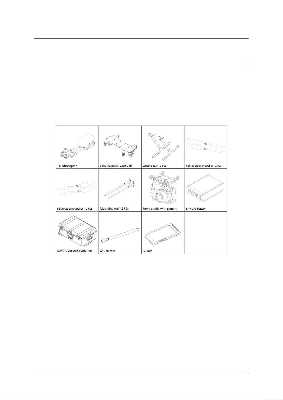
1.1 Kit ................................................ 1
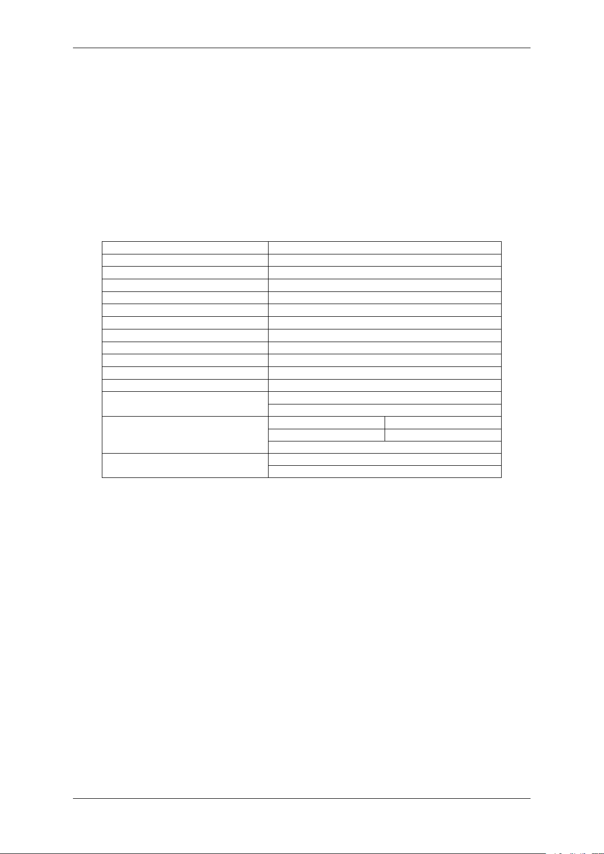
1.2 Specifications .......................................... 2
1.3 Maintenance ........................................... 2
1.4 Storage .............................................. 2
2 Safety rules 3
2.1 Operational restrictions .................................... 3
3 UAV 4
3.1 Parts ............................................... 4
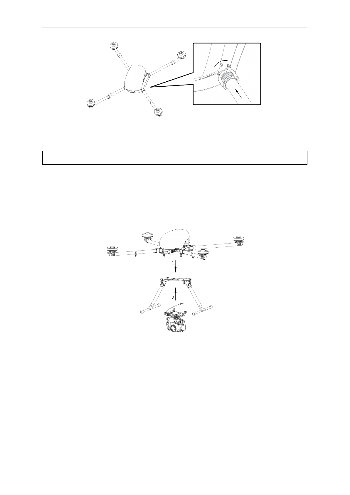
3.2 Assembly ............................................. 4
4 Ground Control System 10
4.1 Kit ................................................ 10
4.2 Deployment and setup ..................................... 10
5 Camera Settings 12
5.1 Sony DSC-RX1RM2 Settings .................................. 12
5.2 Sony DSC-RX1 Settings ..................................... 16
5.3 Offset coordinates ........................................ 18
6 Charger and battery 20
6.1 Safety requirements ....................................... 20
6.2 Preset of the battery charger .................................. 21
6.3 How to connect the battery to the charger .......................... 22
6.4 Battery indication ........................................ 22
6.5 Heating control (for “Arctic” battery) ............................. 23
6.6 Lithium polymer (LiPo) battery recommendations on the use ............... 24
6.7 Storage and discharge ...................................... 24
6.8 Battery recycling ........................................ 24
7 Geoscan Planner 25
7.1 Preset ............................................... 25
7.2 Creating a flight task ...................................... 27
7.3 Areal surveying ......................................... 29
7.4 Linear surveying ......................................... 35
7.5 Flight by points ......................................... 37
7.6 Waiting point .......................................... 38
7.7 Panoramic survey ........................................ 39
7.8 Landing point .......................................... 40
7.9 Pre-launch preparation ..................................... 40
7.10 Flight ............................................... 41
7.11 Cancel .............................................. 41
7.12 Land ............................................... 42
i

CHAPTER
ONE
GENERAL INFORMATION
Geoscan 401 — multifunctional system, that included in basic kit multirotor unmanned aerial vehicle
(UAV) and Geoscan Planner software.
1.1 Kit
• Geoscan 401 unmanned aerial vehicle (UAV)
• UAV’s transport container
• Payload: *
–customized Sony DSC-RX1RM2 camera;
–gyro-stabilized optical-electronic system with FullHD videocamera;
–Topcon B111 GNSS receiver (L1-L2, GPS/GLONASS/BeiDou);
–quantum magnitometer Geoscan QM-Rb-1.
• 37 V LiPo battery
• Left rotation propeller — 2 PCs
• Right rotation propeller — 2 PCs
• Battery charger
• Radio modem
• Radio modem antenna
1

• Radio modem pole
• SDHC card 64 Gb — 2 PCs *
• SD card 4 Gb — 2 PCs *
• USB cable
• UAV antenna
*—Depends on equpment
1.2 Specifications
UAV type multirotor
Engine electric brushless — 4 PCs
Battery 37 V LiPo
Launch/Landing verticaly, in automatic mode, from/to 5 m area
Flight duration up to 1 h
Max wind speed 12 m/s
Speed of flight 0-50 km/h
Min safe flight altitude 25 m
Max flight altitude over start point 500 m
Max takeoff weight 9,3 kg
Max payload mass 2,5 kg
Preparation time before takeoff 5 min
UAV’s overall dimensions folded 70х25х20 cm
unfloded 150х150х43 cm
Photo shooting area in one flight 2 cm/pix quality 0,95 km2
3 cm/pix quality 1,4 km2
5 cm/pix quality | 2,1 km2
Operating temperature range: -20 to +40 °C
-40 to +20 °C (“Arctic” battery)
1.3 Maintenance
Visually inspect UAV for a damage after each flight.
In case, if a propellers are damaged, you can replace it by yourself using spare parts and tools from the
kit.
If structural damage to the airframe or systems is detected, contact Geoscan support.
We recommended to send your UAV to the manufacturer for inspection and maintenance after 80 flights.
1.4 Storage
Geoscan 401 UAV (without battery) are recommended to be stored in a transport containers in dry rooms
at a temperature of 5 to 25 °C and relative humidity not more than 80% without condensation. Service
life — 2 years.
Batteries should be stored in a cool and dry place without direct sunlight, at a temperature of 5 to 25
°C and a relative humidity of 80% without condensation. The optimum voltage level when placing the
battery to storage: 38,5 V.
Service Life — 1 year.
2 Chapter 1. General information

CHAPTER
TWO
SAFETY RULES
For safe use of UAV, follow these operating instructions:
• UAV launch and maintainence can be held only by persons trained according to the “Plan of theo-
retical and practical training of the operator to control the unmanned complex GEOSCAN 401”;
• follow the dealer’s and/or manufacturer’s recommendations and instructions for use of the equip-
ment, as given in this manual and received during operation period;
• before the flight it is necessary to inspect the flight area and make sure that the planned flight
path passes not less than 100 m above the terrain and high-rise objects (mountains, towers, pipes,
transmission towers, etc.);
• don’t launch the UAV if any malfunction is detected;
• after connecting the battery to the UAV it is prohibited to be in the propeller blades rotation plane;
• don’t launch or fly UAV near high power radio transmitters;
• avoid flying above crowded places;
• turn on UAV power only to send flight task or directly before prefight check;
• don’t assemble or disassemble the UAV when the power is on;
• don’t circuit battery pins;
• transportate the UAV only in transport container;
• Don’t hold UAV’s when you move it;
• remove the camera lens cap only before flight mission start;
• don’t modify or change constructive elements of the UAV.
2.1 Operational restrictions
• Operating temperature range: -20 to +40 °С, -40 to +20 °С with “Arctic” battery
• Max wind speed: 12 m/s
The aerial photography complex is not intended for flights during rain, snow and other precipitation.
It is necessary to leave the complex at room temperature for 24 hours after transportation at low tem-
peratures.
3

CHAPTER
THREE
UAV
3.1 Parts
3.2 Assembly
1) Take the landing gears base part and landing gears from the UAV’s transport container.
2) Put landing gears in the landing gears base part tubes.
3) Tighten connecting nuts on landing gears by hands.
4) Fix nuts position by elastic fixators.
4

Fig. 1: Installation and fixation of the landing gears
5) Take the quadcopter from the UAV’s transport container.
6) Remove a protective transport elements.
7) Take the quadcopter’s frame arms out to the sides.
Fig. 2: Quadcopter assembly
8) Move frame arms nuts to the quadcopter’s frame central part and tighten it.
3.2. Assembly 5

Fig. 3: Quardcopter’s nuts moving
Attention: Make sure that the nuts are covered frame pins.
9) Put the quadcopter on landing gears base part.
• Frame loops must be connected with landing gear’s loops.
• Take the servo cradle and position it under the quadcopter’s frame. The frame loops must be
connected with servo cradle’s loops. (see the picture). The camera lens should be directed in the
direction of the slope of the quadcopter fairing.
Fig. 4: Connection of the parts
• Put a mounting rods in loops on the side of the red seals.
6 Chapter 3. UAV

Fig. 5: Connection of the parts
Attention: Make sure that, the rods are fully puted (Rod’s rings must be puted into red seals).
10) Install propellers on the motors. The color markings on the motors and propellers must be the
same. Arrow icon in center of propeller is shows rotate direction to install. Screw each propeller
onto the threads. Rotate a propeller in the opposite direction to unscrew.
Fig. 6: Fixation of the propellers
Attention: Before each start make sure that all propellers are not damaged. Do not use worn,
cracked or damaged propellers.
11) Put payload’s connection cable (if payload connects with UAV) in quardcopter’s slot.
3.2. Assembly 7

Fig. 7: Connection of the payload cable
12) Screw CRL antenna in quadcopter’s arm pin.
Attention: Make sure that the pin is clear. Clear pin by using alcohol-soaked lint-free cloth.
Attention: Do not turn on UAV power without CRL antenna. This may damage the receiver.
Fig. 8: Connection of the CRL antenna
13) Eject payload’s memory cards, format and insert them back. *
*-Depends on equpment
8 Chapter 3. UAV

Fig. 9: Instaling memory card in UAV’s slot (kit with GNSS receiver).
14) Install the battery in battery slot until it stops (Battery pins must be on the left side looking for-
ward).
Fig. 10: Installing of the battery
15) Fix the battery by textile clasp.
3.2. Assembly 9

CHAPTER
FOUR
GROUND CONTROL SYSTEM
This manual assumes deployment of a laptop-based ground control station (not included in the basic
kit).
Table 1: Minimum System Requirements
Operating sys-
tem
MS Windows 7,8,10
CPU Intel Core i3
RAM 4 Gb
GPU type Dedicated
GPU model Nvidia GeForce GT620M, GT630M, 710M, GT720M; AMD Radeon HD 7670M or
equivalent
Table 2: Recommended System Requirements
Operating system MS Windows 7,8,10
CPU Intel Core i5, i7
RAM 8 Gb
GPU type Dedicated
GPU model Nvidia GeForce GT645M, GT745M, 845M, GT720M, 940M and higher
4.1 Kit
• USB flash drive with software
• Radio modem
• Radio modem antenna
• Radio modem pole
4.2 Deployment and setup
1) Take out the CRL modem and antenna from UAV transport case.
2) Screw antenna to CRL modem.
3) Set up the pole and secure the modem on it by screws at the top section.
The stand should be installed either in UAV transport case slot or firmly inserted into the soil by its lower
end.
4) Turn laptop on.
5) Install MdmDisp and Geoscan Planner software from USB flash drive.
10

6) Connect CRL modem to laptop.
CRL modem should be placed at top altitude possible with antenna situated vertically. Do
not set the modem inside the building or car.
Warning: Do not connect the mode to GCS without the antenna! Otherwise the modem may stop
functioning or be permanently damaged.
4.2. Deployment and setup 11

CHAPTER
FIVE
CAMERA SETTINGS
This section contains recommended settings for cameras.
Camera type depends on delivery kit.
5.1 Sony DSC-RX1RM2 Settings
Carfully read Camera Operating Instructions to get information about functions and control elements
before change settings.
Basic camera control elements are shown on the picture:
5.1.1 Camera presets
Geoscan UAVs are equipped with 2 presets for Sony DSC-RX1RM2 cameras.
Use Mode dial near on\off switcher to select preset for your needs.
Preset 1 serves for shooting in normal daylight conditions. The aperture value is fixed, which provides
fixed aperture for better ortophotomosaic generation.
Use these settings for this mode:
• Set Mode dial in 1position.
• Set Focus mode dial in MF position.
• Set Exposure compensation dial in 0position.
• Set Macro switching ring in 0,3m-∞position.
• Set Aperture ring in 4,5 (first mark after 4)
Preset 2 — universal set with automatic variable aperture control (Shutter Priority).
Use these settings for this mode:
• Set Mode dial in 2position.
12

• Set Focus mode dial in MF position.
• Set Exposure compensation dial in 0position.
• Set Macro switching ring in 0,3m-∞position.
The aperture value is not taken into account.
Preset 3 can be used for user settings.
Select settings in menu, go to camera settings (tab 8) and select Memory.
Set Mode dial in 3position and press button in the middle of Control wheel.
5.1.2 Restoring presets
Settings of 1 and 2 presets can be restored, if you change them.
For preset 1 restoring:
• Set Mode dial in position M(Manual aperture control).
• Set shutter speed 1/1000 by Control dial.
• Select ISO —Auto in camera menu.
Press menu button, go to camera settings (tab 8) and select Memory.
Set Mode dial in 1position and press button in the middle of Control wheel.
For preset 2 restoring:
• Set Mode dial in position S(Shutter priority).
• Set shutter speed 1/1000 by Control dial.
• Select ISO —Auto in camera menu.
Press menu button, go to camera settings (tab 8) and select Memory.
Set Mode dial in 2position and press button in the middle of Control wheel.
If you change or reset settings you also need to switch off automatic photo review and shooting by MOVIE
button, set maximum time before powersaving start and reset for file number. Change these settings:
• Switch off Auto Review in user settings (tab 2) and MOVIE Button —Video Mode Only
(tab 6).
Fig. 1: Auto review — off
5.1. Sony DSC-RX1RM2 Settings 13

Fig. 2: «Video mode only» for MOVIE button
• In settings section set Power Saving Start Time —30 min. (tab 2) и File Number —
Reset (tab 5).
Fig. 3: Power saving start time
Fig. 4: File number reset
5.1.3 SD Card Formating
• In settings menu (tab 5) select Format.
14 Chapter 5. Camera Settings

Fig. 5: «Format» option
Attention: All data on SD card will be deleted!
5.1.4 Settings reset
Reset of the camera will delete presets’ shooting settings (Presets 1 and 2)!
1) In settings menu (tab 6) select Setting Reset
Fig. 6: «Setting reset» option
Attention: Do not remove the battery during a reset process!
2) After camera reboot, you need to set Timezone and date, otherwise the settings will not be saved
and this menu will appear at every turn on.
3) Use ON/OFF switcher to turn the camera off.
4) Wait 3 minutes for all settings to be saved (do not disconnect the battery or power cord).
Important: «E:61:00» error may appear on the screen, as the camera is focused to infinity. This
message will not interfere with camera’s function.
5.1. Sony DSC-RX1RM2 Settings 15

5.2 Sony DSC-RX1 Settings
Carfully read Camera Operating Instructions to get information about functions and control elements
before change any settings.
Basic camera control elements are shown on the picture:
• Set shutter speed 1/1000 by Control dial.
• Set Exposure compensation dial in 0(zero) position.
• Set Macro switching ring in 0,3m-∞position.
• Set Focus mode dial in MF position.
• For normal daylight conditions switch Mode dial in M(Manual aperture control) position and
Aperture ring in 4,5 (first mark after 4) position.
• For cloudy weather switch Mode dial in S(Shutter priority) position. The aperture value is not
taken into account in this mode.
To set camera soft parameters, push MENU button, then select parameters according to the following
instructions.
• In user settings menu (tab 1) turn off Automatic preview.
Fig. 7: Turn off automatic preview
• Turn off RF assist and set Extend focus time -No restrictions (2 tab).
16 Chapter 5. Camera Settings

Fig. 8: Turn off RF assist and focus time extend setting.
• Set MOVIE -Video mode only (tab 3).
Fig. 9: Set video mode only
• In settings menu tab 2 set Power saving time -30 min .
Fig. 10: Power saving time
• In memory card menu select File № -Clear.
5.2. Sony DSC-RX1 Settings 17
Other manuals for 401
2
Table of contents
Other Geoscan Drone manuals