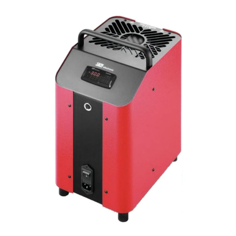
SIKA TP 17165M User manual

Please keep this operating manual for future reference.
If the device is resold, please provide the operating manual along with it.
© SIKA • Ba_TP17M_en • 03/2019 .
Temperature Calibrators
Series TP 17...M
Types TP 17165M • TP 17650M

TP 17...M
- 2 - © SIKA • Ba_TP17M_en • 03/2019
Table of contents page
0About this operating manual.........................................................................................3
1Device description .........................................................................................................4
1.1 Intended use................................................................................................................5
1.2 Warranty......................................................................................................................6
1.3 Exclusion of liability ....................................................................................................6
2Safety Instructions ........................................................................................................6
3Construction and function.............................................................................................8
4Commissioning and operation ......................................................................................9
4.1 Operating conditions ...................................................................................................9
4.2 Electrical connection ................................................................................................10
4.3 Preparation of the calibrator ....................................................................................11
4.4 Switching on, cool down and switching off ...............................................................12
4.5 Operating modes.......................................................................................................13
5Operation .....................................................................................................................14
5.1 Control elements of the controller (controller type K32SK)....................................14
5.2 Calibration (calibration mode) ..................................................................................15
5.3 Set a set temperature (set point mode)....................................................................17
6Testing process / Calibration ......................................................................................18
6.1 Testing temperature sensors ...................................................................................18
6.2 Testing process .........................................................................................................18
7Troubleshooting ..........................................................................................................20
7.1 Return shipment to the manufacturer .....................................................................21
8Maintenance, cleaning and transport .........................................................................22
8.1 Maintenance..............................................................................................................22
8.2 Cleaning.....................................................................................................................23
9Decommissioning and disposal ..................................................................................24
10 Technical Data.............................................................................................................25
10.1 Characteristics series TP 17…M ...............................................................................25
10.2 Heating and cooling periods .....................................................................................27
Copyright notice:
The reproduction, distribution and utilization of this operating manual as well as the communication
of its contents to others without express authorization is prohibited. Offenders will be held liable for
the payment of damages. All rights reserved in the
event of the grant of a patent, utility model or
design.

TP 17...M About this operating manual
Technical changes reserved - 3 -
0About this operating manual
•The operating manual is aimed at specialists and semi-skilled personnel.
•Before each step, read through the relevant advice carefully and keep to the specified
order.
•Thoroughly read and understand the information in the section "Safety Instructions".
•For calibrators with a cooling function, the term "Cooling" is also used for tempera-
tures below room temperature, in the meaning of "Heating".
If you have any problems or questions, please contact your supplier or contact us directly
at:
Dr. Siebert & Kühn GmbH & Co. KG
Struthweg 7-9 • D - 34260 Kaufungen
+49 5605 803-0 • +49 5605 803-555
info@sika.net • www.sika.net
Hazard signs and other symbols used:
CAUTION! Electric current!
This sign indicates dangers which could arise from handling of electric current.
WARNING! / CAUTION! Risk of injury!
This sign indicates dangers that cause personal injuries that can lead to health defects or
cause considerable damage to property.
CAUTION! High temperature!
This sign indicates dangers resulting from high temperature that can lead to health defects or
considerable damage to property.
CAUTION! Material damage!
This sign indicates actions which could lead to possible damage to material or environmental
damage.
ADHERE TO OPERATING MANUAL!
NOTICE!
This symbol indicates important notices,
tips or information.
NO DOMESTIC WASTE!
The device must not be disposed of to-
gether with domestic waste.
Pay attention to and comply with infor-
mation that is marked with this symbol.
Follow the specified instructions and steps.
Adhere to the given order.
Check the specified points or notices.
Reference to another section, document or
source.
•Item.

Device description TP 17...M
- 4 - © SIKA • Ba_TP17M_en • 03/2019
1Device description
The calibrators of the series TP 17...M serve for testing and calibrating different temperature
measuring instruments and temperature sensors, as well as for measurement of tempera-
tures.
The portable instruments are of compact and robust construction and thus allow use directly
on-site or in a laboratory.
The TP 17...M series is used for service purposes and for different industrial and laboratory
tasks.
Thus, for example, thermometers, temperature switches/thermostats, resistance thermom-
eters and thermo-elements can be directly connected and checked.
Versions:
The series TP 17...M includes the following calibrator types:
TP 17165M
TP 17650M
cooling and heating
heating
Type plate:
You find the type plate on the rear of the device.
It includes the type designation, the serial number and the key electric specifications.
Unpacking:
Carefully unpack the unit to prevent any damage.
Check the completeness of the delivery based on the delivery note.
Save the packaging!
Temperature calibrators are delivered in special protective packaging.
Save the packaging for returning the instrument safely to the manufacturer for recal-
ibration or repair.

TP 17...M Device description
Technical changes reserved - 5 -
Scope of delivery and accessories:
Scope of delivery: Accessories (optional):
Metal block calibrator according to order
data.
Mains cable.
Sleeve exchange tools.
Test certificate.
Operating manual.
Protective packaging and transport pro-
tection.
Transport case.
Transport bag (only TP 17650M).
Adapter sleeves.
DAkkS certificate.
Works certificate.
IMPORTANT!
Use the type plate to check if the delivered unit corresponds to your order.
In particular, for devices with electrical components, check to see if the correct power
supply voltage is specified.
1.1 Intended use
The calibrators of the TP 17...M series may only be used for testing and calibration of suitable
temperature measuring instruments, temperature sensors and for measuring temperatures.
The calibrators may not be used for warming up or heating other parts or gases.
The calibrators have been designed for indoor use only.
The operational safety of the device supplied is only guaranteed by intended use. The speci-
fied limits (§ 10 "Technical Data") may under no circumstances be exceeded.
CAUTION! Risk of burns!
The calibrator can become very hot when in operation. Touching hot parts can result in
serious injuries.
Never touch the metal block, the adapter sleeve or the test specimen at temperatures
above 35 °C or below 10 °C.
Allow the calibrator to cool before you remove the test specimen, change the adapter
sleeve or switch off the machine.
CAUTION! Material damage!
The opening in the metal block of the calibrator is only intended to be used with adapt-
er sleeves.
Using heat transfer media (oil, thermal paste or other media) can lead to incorrect
measurements and damage to the calibrator.
Never fill the metal block opening with a heat transfer medium.
It is your responsibility to select the instrument which is suitable for your specific application,
to connect it correctly, to carry out tests and to maintain all the components.

Safety Instructions TP 17...M
- 6 - © SIKA • Ba_TP17M_en • 03/2019
1.2 Warranty
The calibrator is under guarantee for 12 months as from the date of delivery for construction
errors or material defects. The guarantee is limited to repair or replacing the calibrator.
SIKA also provides an extra 5-year guarantee for calibrators which are calibrated and in-
spected annually by the SIKA-DAkkS laboratory.
Opening the calibrator, unauthorised repairs or incorrect use or installation of the calibrator
automatically result in the warranty being rendered null and void.
1.3 Exclusion of liability
We accept no liability for any damage or malfunctions resulting from incorrect installation,
in-appropriate use of the device or failure to follow the instructions in this operating manual.
2Safety Instructions
Before you install the TP 17...M, read through this operating manual carefully. If the in-
structions contained within it are not followed, in particular the safety guidelines, this
could result in danger for people, the environment, and the device and the system it is
connected to.
The TP 17...M corresponds to the state-of-the-art technology. This concerns the accuracy,
the operating mode and the safe operation of the device.
In order to guarantee that the device operates safely, the operator must act competently and
be conscious of safety issues.
SIKA provides support for the use of its products either personally or via relevant literature.
The customer verifies that our product is fit for purpose based on our technical information.
The customer performs customer- and application-specific tests to ensure that the product is
suitable for the intended use. With this verification all hazards and risks are transferred to our
customers; our warranty is not valid.
Qualified personnel:
The personnel who are charged for the installation, operation and maintenance of the
TP 17...M must hold a relevant qualification. This can be based on training or relevant tui-
tion.
The personnel must be aware of this operating manual and have access to it at all times.
General safety instructions:
In all work, the existing national regulations for accident prevention and safety in the
workplace must be complied with. Any internal regulations of the operator must also be
complied with, even if these are not mentioned in this manual.
Ensure that the complete operating instructions are always available in excellent condi-
tion at the calibrator installation site.
Degree of protection according to EN 60529:
Ensure that the ambient conditions at the site of use do not exceed the requirements for
the stated protection rating (§ 10 "Technical Data").

TP 17...M Safety Instructions
Technical changes reserved - 7 -
Structural safety in accordance with EN 61010-1:
The calibrator must be installed in such a way that the requirements for structural safety
are met.
Only use the TP 17...M if it is in perfect condition. Damaged or faulty devices must be
checked without delay and, if necessary, replaced.
If problems cannot be cleared, immediately shut down the calibrator and ensure that it
cannot be started up accidentally.
Never leave the calibrator unattended when it is in operation or in the cooling phase.
Do not remove or obliterate type plates or other markings on the device, as otherwise the
warranty is rendered null and void.
Special safety instructions:
Thermal fuse!
The calibrator is equipped with a temperature fuse that works independently. If there is
an over-temperature in the inside of the housing, the power supply to the heating system
is cut off. The calibrator cannot then be started any more.
After it has cooled, send the calibrator for inspection to SIKA.
The calibrator may not be used in an explosion-endangered atmosphere (ignitable or ex-
plosive atmosphere).
Remove all the easily flammable media from the vicinity of the calibrator.
Ensure that the calibrator cannot come in contact with easily flammable or explosive
media.
Operate the calibrator only in the temperature range permissible for the test sample.
Ensure that the test sample is securely fixed in the calibrator.
Use only suitable adapter sleeves.
When doing so, also ensure that the structural safety of the calibrator is retained.
Further warnings that are specifically relevant to individual operating procedures or activities
can be found at the beginning of the relevant sections of this operating manual.

Construction and function TP 17...M
- 8 - © SIKA • Ba_TP17M_en • 03/2019
3Construction and function
Construction:
The calibrator consists of a robust, black-and-red painted steel housing and has a carry-
ing handle at the top .
The front part of the housing holds the electronics of the TP 17...M and the controller with
display and control elements.
On the front side are the main switch with fuse and mains plug connection as well as the
service and data interface .
The rear part of the housing holds a heat-insulated metal block with heating or cooling el-
ements and an integrated sensor for the reference temperature.
The grille for the exhaust of the calibrator ventilation is located the upper plate of the
housing in the range of the opening of the metal block.
In the base, there are grilles for cooling the calibrator. The in-built fans control the inlet air
of the housing and of the metal block .
An overview of the most important components of the TP 17...M:
Carrying handle.
Steel housing.
Controller with display and control elements.
Main switch with fuse and mains plug socket.
Metal block (Dry block).
Calibrator ventilation:
Exhaust through upper housing grilles.
Service interface.
Calibrator, bottom view:
Calibrator ventilation
Inlet air for housing cooling.
Inlet air for metal block cooling.
Function:
Adapter sleeves that are suitable for the temperature sensors or temperature measuring in-
struments to be tested are inserted in the calibrator (§ 4.3 "Preparation of the calibrator").
They give the test specimen a secure fit and ensure optimum heat transfer.
Afterwards, the calibrator can be switched on (§ 4.4).
The calibrator heats or cools the metal block to the set temperature. As soon as this temper-
ature has been reached and is stable, the calibration of the test specimen can be carried out.
Then, the next test point is approached or the testing procedure is ended.

TP 17...M Commissioning and operation
Technical changes reserved - 9 -
4Commissioning and operation
CAUTION! Risk of injury or material damage!
The calibrator can become very hot during operation. If the machine is operated without
supervision, third-party persons in the vicinity could get injured. Moreover, flammable
material could get into the machine and cause significant damage to property.
Never leave the calibrator unattended when it is in operation or in the cooling phase.
For safe operation of the calibrators of the TP 17...M series, a proper commissioning proce-
dure is necessary.
Commissioning includes the installation, the electrical connections, the preparation for the
calibration as well as correct switching on and off of the device.
Further, a visual inspection for damage is required before use.
The required steps are described in the following sections.
IMPORTANT!
Please also follow the instructions for intended use (§ 1.1), the safety instructions
(§ 2) and the information on the ambient conditions (p. 26).
4.1 Operating conditions
Select a safe installation site for commissioning the machine.
Installation site and operating position:
Only suitable for indoor use, do not use outdoors.
Operate only in the vertical position on an even surface. The surface must be stable,
clean, and dry.
If the operation positions do not conform to the above, the structural safety and the speci-
fied properties of the calibrator are not guaranteed.
At higher testing temperatures, please use a sufficiently big, fire-resistant supporting
surface.
Sufficient clearance around the machine
On the front side > 1 m, behind and to the sides > 0.5 m. Head clearance and sufficient
clear space above the machine.
Sufficient ventilation must be ensured.
Do not operate in the vicinity of flammable materials.
Do not install in a cupboard or other similar object.
The ventilation openings must not be blocked or covered.
The machine must be so installed that it can be switched off at any time.
IMPORTANT! "KILL" switch!
The plug of the mains connecting cable serves as a "KILL" switch.
Ensure that the plug is always easily accessible and easy to reach.
In an emergency, pull the plug, so that the machine is isolated from the mains.

Commissioning and operation TP 17...M
- 10 - © SIKA • Ba_TP17M_en • 03/2019
4.2 Electrical connection
Check the following points before you connect the calibrator:
Operate the machine only with the approved supply voltage (§ 10). Ensure that the
mains voltage is the same as that specified on the type plate.
Connect the calibrator only to a properly installed and earthed 3-pole outlet.
Do not use any extension cables or adapter plugs.
IMPORTANT! Mains connecting cable!
The mains connecting cable may only be replaced by an equivalent cable.
Use only original cables from SIKA or approved cables of the same type with the cor-
rect design as replacements (§ 10.1 "Electrical characteristics").
Connect TP 17...M:
Connect the mains connecting cable with the connector plug of the TP 17...M.
Insert the plug of the mains connecting cable in a suitable outlet.

TP 17...M Commissioning and operation
Technical changes reserved - 11 -
4.3 Preparation of the calibrator
The preparations for the test task must be carried out with the calibrator switched off and
cooled to ambient temperature.
CAUTION! Risk of burns!
The calibrator can become very hot when in operation. Touching hot parts can result in
serious burn injuries.
Never touch the metal block, the adapter sleeve or the test specimen at temperatures
above 35 °C or below 10 °C.
Allow the calibrator to cool before you remove the test specimen, change the adapter
sleeve or the calibration insert or switch off the machine.
Adapter sleeves:
Adapter sleeves with single or multiple holes are used for the calibration of straight temper-
ature sensors.
To achieve the specified accuracy of the calibrators (§ 10.1) the temperature
sensor (test specimen) and the adapter sleeve must be matched to one another:
•The borehole of the adapter sleeve may be a maximum of 0.5 mm larger than
the diameter of the test specimen.
•The measurement element of the test specimen must be located in the ho-
mogeneous temperature zone of the adapter sleeve.
Inserting:
Only use the supplied adapter sleeves
made of the appropriate material.
If in doubt, contact SIKA for clarification.
The appropriate adapter sleeve is inserted
into the metal block with the aid of the
sleeve exchange tool.
Removing and cleaning:
Let the calibrator cool before you remove
the adapter sleeve.
Pull the adapter sleeve out of the metal
block with the help of the sleeve exchange
tool.
Clean the adapter sleeve and the metal block.
This prevents the adapter sleeve from getting stuck in the metal block.
Adapter sleeves and sleeve exchange tool

Commissioning and operation TP 17...M
- 12 - © SIKA • Ba_TP17M_en • 03/2019
4.4 Switching on, cool down and switching off
IMPORTANT!
Follow the instructions and notes of the section (§ 4.1).
For reasons of safety, upon switching on the calibrator, the fan runs at the fastest speed. As
soon as the internal reference has measured a safe block temperature, the fan speed is ad-
justed.
Switching on:
Turn on the main switch.
The controller is initialised.
tESt appears in the upper display.
The version number e.g. rL 1.6 appears on the lower display.
Initialization is completed after approx. 5 seconds and the calibration mode (§ 5.2) is au-
tomatically displayed.
The installed heating elements automatically adjust the metal block from the room
temperature to the set temperature set at the controller.
IMPORTANT! Keep in mind after transport or storage!
After transport, storage or long periods of non-use, moisture can seep into the heating
elements (magnesium oxide).
For drying, the calibrator must be slowly heated up. During this process, the calibrator
has not yet reached the required insulation voltage for protection class I.
For drying the heating elements, heat the calibrator for at least 15 min to 120 °C.
Cool down the calibrator:
CAUTION! Risk of burns!
The calibrator can become very hot when in operation. Touching hot parts can result in
serious injuries.
Never touch the metal block, the adapter sleeve or the test specimen at temperatures
above 35 °C or below 10 °C.
In order to cool down the metal block / calibration liquid quickly, set the set tempera-
ture to a low temperature, e.g. room temperature.
The installed fan gently and automatically switches to a higher speed for heating instru-
ments, thus providing more cooling air. The LED OUT 2 indicates the status of the output for
the fan control. If the LED OUT 2 lights up, the fan is running at high speed. If the LED OUT 2
does not light up, the fan is running at low speed.
The controller switches the active cooling on for heating / cooling instruments. The LED OUT
2 indicates the status of the output for the active cooling. If the LED OUT 2 lights up, the ac-
tive cooling is running. If the LED OUT 2 does not light up, the cooling is not active.

TP 17...M Commissioning and operation
Technical changes reserved - 13 -
IMPORTANT! Mains failure or separation from the mains!
If there is a mains failure, or if the main switch is turned off, or upon removal of the
mains connection ("EMERGENCY STOP"), the built-in fan does not blow any more cooling
air.
Sufficient thermal de-coupling between the metal block and the housing is nonetheless
guaranteed
Switching off:
CAUTION! Before switching off, pay attention to the block temperature!
The calibrator should first reach a low block temperature before switching off. When
switching off at high temperatures, the calibrator or the test specimen may be damaged.
Switch off the calibrator only when the metal block has reached room temperature.
Check whether the metal block has cooled down to room temperature.
Switch off the calibrator via the main switch.
Disconnect the calibrator from AC power if no further testing is required.
Unplug the power cord from the wall outlet.
Clean the calibrator after use (§ 8.2).
4.5 Operating modes
During operation, there are two operating modes:
•Calibration mode:
This is the normal operating mode in which the calibration of test specimens is carried
out (§ 5.2).
•Set point mode:
The set temperatures can be entered in this mode (§ 5.3).
Press the key Pto switch between the calibration and set point mode.

Operation TP 17...M
- 14 - © SIKA • Ba_TP17M_en • 03/2019
5Operation
You operate the calibrator via the controller. Depending on the calibrator type, you operate
the calibrator additionally via the thumbwheel of the magnetic stirrer and the switch for the
external reference.
The controller is equipped with two 4-digit LED displays for reference and set temperature as
well as with indicators and control elements which are described in the following section.
5.1 Control elements of the controller (controller type K32SK)
Overview and function of the control elements of the controller:
6 -
key
•Increasing values to be set.
•Display of current heating capacity in %.
7 – U key
•The function of the key is not used.
8 - LED OUT 1
Indicates the status of the output for the tem-
perature control:
☼ If LED OUT 1 is lit, the calibrator is heating.
If LED OUT 1 is not lit, the calibrator is not
heating.
9a - LED OUT 2
a) Heating instrument
Indicates the status of the output for the fan
control:
☼ If LED OUT 2 is lit, the fan is running at high
speed.
If LED OUT 2 is not lit, the fan is running at
low speed.
9b - LED OUT 2
b) Heating and cooling instrument
Indicates the status of the output for the tem-
perature control:
☼ If LED OUT 2 is lit, the calibrator is cooling.
If LED OUT 2 is not lit, the calibrator is not
cooling.
1 - Upper display (red)
•Calibration mode:
Display of current reference temperature.
•Set point mode:
Display of SP1 (Set point 1).
2 - Lower display (green)
•Display of set temperature.
•Display of heating / cooling capacity.
•Display of operating duration.
3 - LED SET
•The function of the LED is not used.
4 - P key
•Switching to set point mode.
•Input confirmation.
•Access "ConF" menu (only for service).
5 -
key
•Reducing values to be set.
•Display of operating hours.

TP 17...M Operation
Technical changes reserved - 15 -
5.2 Calibration (calibration mode)
As soon as the calibrator has been switched on, it switches to the calibration mode after ini-
tialization.
5.2.1 Display of reference and set temperature
The current reference temperature is displayed in the upper and the set temperature in the
lower of the display.
Upper display (red):
The red display shows the current temperature of the
metal block.
Lower display (green):
The green display shows the current set temperature
chosen by the user.
5.2.2 Display of temperature control
The LED OUT 1 indicates the status of the temperature control:
•If LED OUT 1 is lit the temperature control is ac-
tive. The heating or cooling is switched on.
•If LED OUT 1 is not lit the heating or cooling is
switched off.
If the LED OUT 1 lights up permanently, the calibrator
is heating up. The temperature control is active so that
the set point is reached as quickly as possible.
If the set temperature has almost been reached,
the LED OUT 1 begins to flash.
The temperature control is activated at increas-
ingly shorter intervals. Thereby, a too strong
overdriving is prevented.
To ensure good temperature stability, the cycle
time of the controller is set low.
The temperature control is now often activated
but only for a short time.
Display of reference and set tempera-
ture
Temperature control active
The control is done by PID algorithm.

Operation TP 17...M
- 16 - © SIKA • Ba_TP17M_en • 03/2019
5.2.3 Display of fan / cooling control
The LED OUT 2 indicates the status of the output for the fan / cooling control:
a) Heating instrument (TP 17650M)
The LED OUT 2 indicates the status of the output for
the fan control:
•If the LED OUT 2 is lit the fan is running at high
speed.
•If the LED OUT 2 is not lit the fan is running at
low speed.
b) Heating and cooling instrument (TP 17165M)
The LED OUT 2 indicates the status of the output for the cooling control:
•If LED OUT 2 is lit the temperature is decreased.
•If LED OUT 2 is not lit the cooling is switched off.
5.2.4 Display of heating / cooling capacity and operating duration
In calibration mode, you can check the heating or cooling capacity and the operating duration
of the calibrator. The current values of the calibrator appear on the lower display (green).
Heating or cooling capacity:
Hold down the key.
The current heating and cooling capacity is displayed in % of the maximum capacity.
"H" indicates the heating capacity and "C" indicates the cooling capacity.
Operating duration:
Briefly press the key.
The current number of operating hours of the calibrator is displayed for ~5 s.
5.2.5 ConF menu
In the ConF menu, system parameters of the calibrator can be set. These settings may only
be carried out by authorised SIKA personnel.
This menu is protected by a password.
CAUTION! Material damage!
The ConF menu is protected by a password. Unauthorised access can cause damage to
the calibrator.
Exit the menu by pressing the P key twice.
Fan / cooling control active

TP 17...M Operation
Technical changes reserved - 17 -
5.3 Set a set temperature (set point mode)
In this operating mode it is possible to modify a saved set temperature.
Press the Pkey shortly.
The currently active set point memory, e.g. SP 1 (set
point 1), is displayed by the upper display.
The respective set temperature is displayed by the
lower display.
Press the key to increase the set temperature.
Press the key to decrease the set temperature.
Press the Pkey again to confirm the new set point.
The new set point is saved and the controller returns to the calibration mode.
NOTES:
•Press the and key to raise and lower the value by 0.1 respectively. If the keys
are held pressed for at least one second, the value increases or decreases quickly and
after two seconds even more quickly; this means the desired value can be reached rapid-
ly.
•If no key is pressed in the set point mode for approx. 15 seconds, the device auto-
matically returns to the calibration mode.
Set temperature setting

Testing process / Calibration TP 17...M
- 18 - © SIKA • Ba_TP17M_en • 03/2019
6Testing process / Calibration
CAUTION! Risk of burns!
The calibrator can become very hot when in operation. Touching hot parts can result in
serious injuries.
Never touch the metal block, the adapter sleeve or the test specimen at temperatures
above 35 °C or below 10 °C.
Allow the calibrator to cool before you remove the test specimen, change the adapter
sleeve or switch off the machine.
6.1 Testing temperature sensors
A separate temperature measuring instrument connected to the test specimen is required to
test the temperature sensors
By comparing the temperature displayed at the external measuring instrument with the ref-
erence temperature it is possible to assess the status of the test specimen. Remember that
the test specimen requires a short period of time until it absorbs the temperature of the
metal block.
CAUTION! Incorrect results!
It is not possible to calibrate earthed thermal elements, because the heating block is
earthed and any measurement would produce incorrect results.
6.2 Testing process
Before the testing process:
Before the start of the testing process, check whether
the instructions regarding the installation site and the operational position have been
complied with (§ 4.1).
the electrical connections have been made correctly (§ 4.2).
the correct measuring insert has been selected for the testing process (§ 4.3).
the test specimen is securely fixed in the calibrator.
the calibrator has sufficient structural stability.

TP 17...M Testing process / Calibration
Technical changes reserved - 19 -
Performing testing process:
During the testing process, one or more test points are approached and the reference tem-
perature of the calibrator is compared with the measured temperature of the specimen.
Set the set temperature to the value of the first test point.
The temperature control regulates the metal block to the temperature of the test point.
Wait until the temperature has been reached and is sufficiently stable for your checking.
Also note that the temperature of the specimen is stable and transients are finished.
Write down the reference temperature and the temperature of the specimen for your test
protocol.
Set the calibrators gradually to the set values of the further test points and proceed as
described above.
Terminate / cancel testing process:
If the testing process has to be terminated or cancelled, the calibrator must be brought in a
safe operational state.
Set the set temperature to a low value e.g. room temperature.
Wait until the calibrator has sufficiently cooled down.
Don’t let the calibrator unattended at high temperatures.
After the testing process:
Allow the calibrator to cool to room temperature.
Note the instructions in the section "Switching on, cool down and switching off" (§ 4.4).
Clean the calibrator (§ 8.2).

Troubleshooting TP 17...M
- 20 - © SIKA • Ba_TP17M_en • 03/2019
7Troubleshooting
CAUTION! Material damage!
The TP 17...M cannot be repaired by the user! In case of a defect, the device must be re-
turned to the manufacturer for repair.
Never open the TP 17...M and perform any repair yourself.
The following table details what problems you can solve yourself and how to solve them.
If you are unable to remedy any particular problem, then immediately disconnect the calibra-
tor in order to protect it from unintended operation.
Contact your supplier or directly SIKA. Please send the device for repair with a brief descrip-
tion of the problem, the environmental conditions and the length of time the device was oper-
ational before the problem occurred.
Problem Possible cause Remedy
- - - - Interruption of the internal refer-
ence sensor or the internal refer-
ence sensor is defective.
Service call required.
uuuu
Measured temperature under the
limit value of the internal refer-
ence sensor (under range -200 °C)
oooo
Measured temperature above the
limit value of the internal refer-
ence sensor
(over range +850 °C)
ErEP
Possible fault in the EEPROM
memory of the controller.
Press the P key
Fan not running.
The fan is defective or blocked and
the temperature switch has trig-
gered.
Service call required.
End temperature is not
achieved.
Solid state relay is defective or the
heating / cooling element has
short circuited or aged.
Service call required.
Sensor break.
External reference sensor not
properly connected.
Recheck connection and connect
properly.
Cable break or short circuit.
Service call required.
No display.
Controller defective.
Service call required.
Calibrator cannot be
switched on.
Power supply not available or
thermal fuses defective.
Check the power supply and
thermal fuses.
Residual current circuit breaker
has tripped due to moisture in the
heating cartridges.
Service call required.
This manual suits for next models
2
Table of contents
Other SIKA Measuring Instrument manuals
SIKA
SIKA VO VA Series User manual

SIKA
SIKA TP 18 200 E User manual

SIKA
SIKA TP37 series User manual

SIKA
SIKA TP 37166E.2 User manual

SIKA
SIKA TP 17 *** M Series User manual

SIKA
SIKA VE Series User manual

SIKA
SIKA TP 28 1300 E Series User manual
SIKA
SIKA Type Q User manual
SIKA
SIKA Idroscan User manual
SIKA
SIKA E2 User manual