3
Contents
1.0 General safety precautions ................................... 3
1.1 Dangers ................................................................ 3
1.2 Field of application ................................................ 3
1.3 Technical Specifications ....................................... 3
1.4 Construction .......................................................... 3
2.0 Installation ............................................................. 4
2.1 Coupling diagram .................................................. 6
2.2 Test run ................................................................. 7
3.0 Daily usage – user instruction .............................. 7
4.0 Maintenance ......................................................... 7
4.1. Trouble shooting................................................... 7
5.0 Liability .................................................................. 8
6.0 Declaration of conformity....................................... 9
1.0 General safety precautions
IMPORTANT – Please study all the instructions before
mounting and use.
Please keep these instructions in a safe place and in-
struct all users in the function and operation of the pro-
duct.
Do not dismantle any factory-mounted parts, since it
impedes the use of the equipment.
All electrical installations must be carried out by an
authorised electrician.
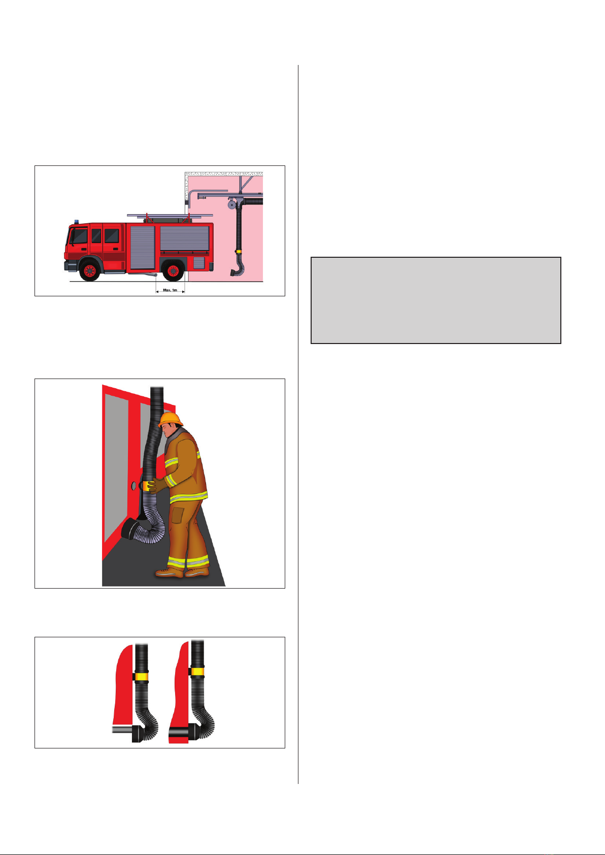
1.1 Dangers
Danger of mutilation when dismounting the hose/nozzle
from the exhaust. Be careful.
Hoses mounted with spring balance F/LR: Guide it slow-
ly. If released it will accelerate out of control.
To minimize the risk of danger all instructions in this
manual must be followed carefully.
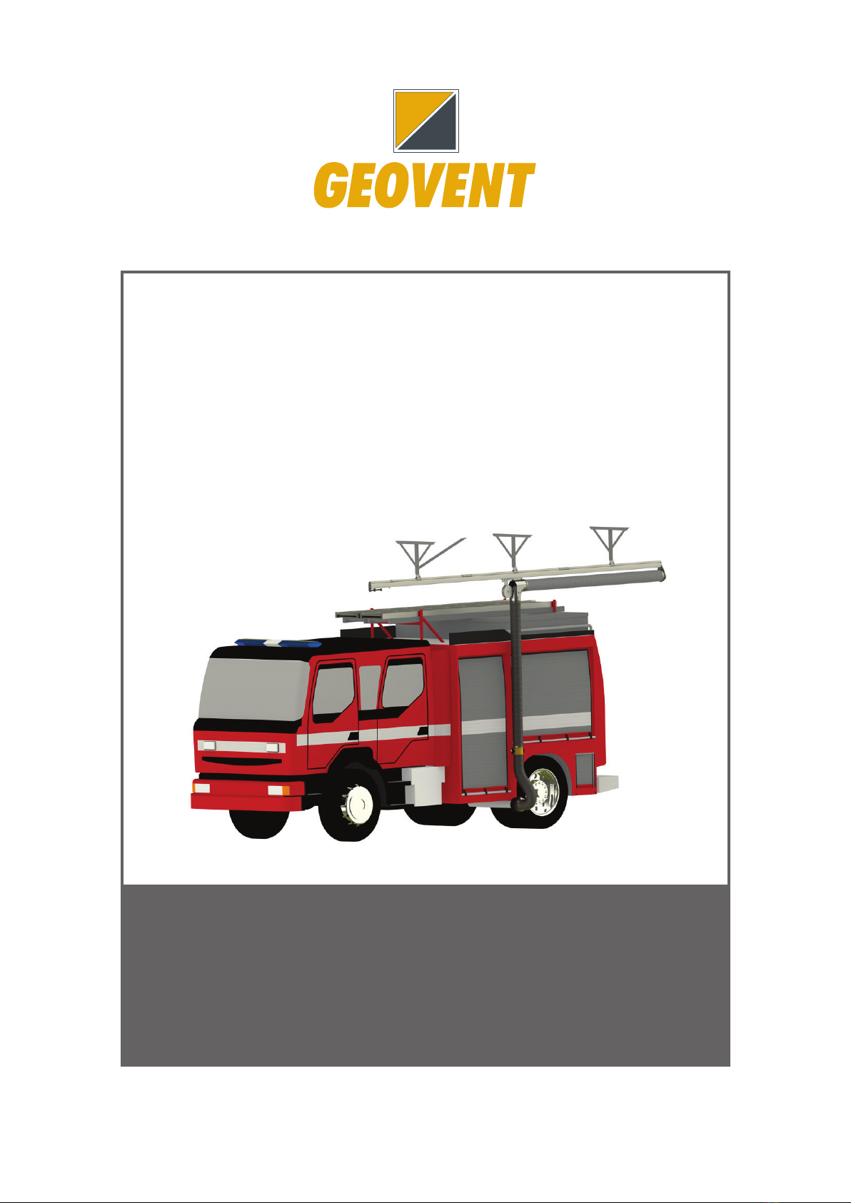
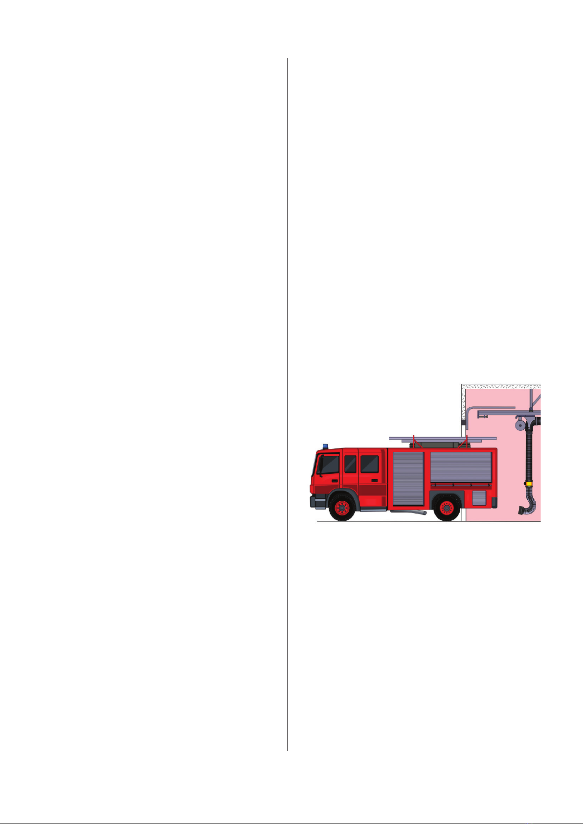
1.2 Field of application
GEOVENT Magnetic rail system is developed for the ex-
traction of exhaust and welding smoke. When installed
correctly the MRSP allows a vehicle to be placed in po-
sition in a safe manner. The hose is extended and fas-
tened to the exhaust of the vehicle.
Alternatively the MRSP can be fitted with an extraction
arm and be used for welding.
1.3 Technical Specifications
Temperature extracted air: Max. 170°C
Temperature, surroundings: Min. 0 - 50°C
If the extracted air is hotter than 170°C the standard
hose will melt. To prevent this, several precautions can
be taken. See trouble shooting in section 4.1.
Noise
The Magnetic rail system Premium in itself does not pro-
duce any noise. The noise level relies on a number of
factors, primarily the diameter of the hose and the extra-
cted air flow. If the hose is too narrow, noise will occur.
Optimal air flow
A number of factors must be taken into consideration
when selecting the hose for the Magnetic rail system
Premium. An important factor is the air flow:
Hose ø125 mm 600 m3/h
Hose ø150 mm 1.000 m3/h
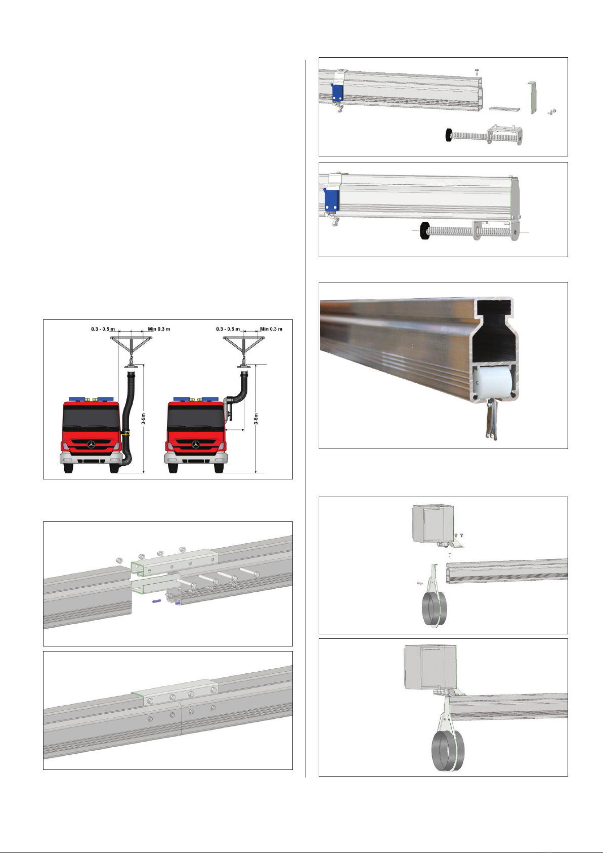
1.4 Construction
Magnetic rail system example
A: Spiro pipe ø160 with reduction valve for pressurized
air.
B: Fan MSFG-200-3 1,1kW – can deliver up to 2.100
m³/h.
C: Trolly with mounted spring balance.
D: Connection for rail system. Rails come in lengths of 2
meter and can be combined to suit your needs.
E: Suspension bracket for ceiling mounting.
F: Decoupling switch.
G: End stop