Geovent GeoFilter GFB2 Tower 6-2 User manual

GFB2 TOWER
GeoFilter GFB2 Tower 6-2, GeoFilter GFB2 Tower 9-3,
GeoFilter GFB2 Tower 12-4
INSTRUCTION MANUAL
www.geovent.com
Version 1.0 03.11.21

2

3
Contents
1.0 Introduction .............................3
2.0 Safety ................................3
2.1 General safety ..........................3
2.2 Danger ................................4
3.0 Machine oveview ........................4
3.1 Description ............................4
3.2 Intended use ...........................4
3.3 Machine specifications ....................4
3.3.1 Design ..............................4
3.3.2 Technical data ........................5
4.0 Transport, handling and storage ............5
5.0 Assembly, installation and start of operation ...5
5.1 Location ...............................5
5.2 Assembly ..............................5
5.3 Control and test of the security systems ......5
6.0 Commissioning .........................6
7.0 Control, test and maintenance .............6
7.1 Control ................................6
7.2 Maintenance ...........................6
7.3 Exchange of filter elements ................6
8.0 Cleaning ...............................7
9.0 Troubleshooting .........................7
10.0 Dismantling, disabling and scrapping........7
11.0 Documents and drawings.................7
12.0 Liability ..............................8
13.0 Declaration of conformity .................9
14.0 Appendix ............................10
14.1 Spare part list .........................10
1.0 Introduction
This manual is made and designed in order to facilitate
the best and most secure interaction with the product.
The manual is relevant for people involved in transpor-
tation, stocking, installation, using, maintaining and all
other thinkable interaction with the product.
The manual must be read in full and understood before
interacting with the product.
When the manual has been read and understood in full,
the table of contents can be used to find the relevant
information in each case.
The product is manufactured by:
Geovent A/S
Hovedgaden 86
DK-8861 Løgstrup
DENMARK
Tel.: (+45) 86 64 22 11
E-mail: [email protected]
www.geovent.com
This manual is to be used for all interactions with the
product including: Transportation, stocking, installation,
operation and maintenance.
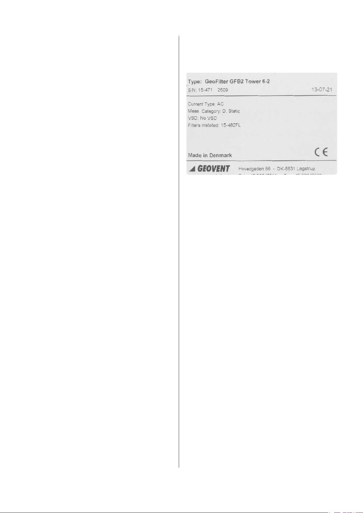
This product is marked with: (example)
2.0 Safety
2.1 General safety
Carefully read this manual before use and observe the
safety instructions in order to avoid injuries!
Keep this manual in a safe place!
Secure that all users of the product have read this ma-
nual and that they follow the instructions as described.
Observe all instructions marked on the product!
Observe the indications of the manufacturer.
Never use the product if you are in doubt about how it
works or what you should do.
When doing maintenance or replacing filters, follow the
instructions in chapter 7.0.
Power cables and pneumatic air hoses should be repla-
ced at once, if they are damaged. This should only be
done by authorised and qualified personnel.
Do not modify the product or use spare parts from other
suppliers than Geovent, as this may hamper the product
and the function.
All electrical installations must be carried out by an
authorised electrician.
2.2 Danger
You must wear safety gloves when handling or using the
product to protect your hands from scratches etc.
Be aware that the product may tilt when you move it.
You must handle the product with care and tie it safely to
the truck or the fork lift when it is in transport.
Place the filter on a solid, flat foundation (e.g. a
concrete floor) and anchor it. Allow space to perform fil-
ter changes.

4
When you change the filter cartridges, follow the instruc-
tions in chapter 7.3.
While opening, cleaning and maintaining the unit or
while changing parts, disconnect the unit from the mains
supply and secure it from being restarted.
In case of an accident or a fire:
- Call for help.
- Disconnect the product from the mains supply.
- Follow the normal and local requirements in case of an
accident or a fire.
In case of problems:
- Disconnect the product from the mains supply.
- Inspect the product to see if a repair is possible.
- If a repair is not possible you should dispose of the
product. Please follow the instruction for disposal in
chapter 10.0.
3.0 Machine overview
3.1. Description
GFB2 Tower is a filter unit that is used for different fil-
tering needs. The product contains filter media, which
must be selected according to the specific filtration need.
3.2 Intended use
The GFB2 Tower is used to filter the extracted air from
industrial processes such at welding, grinding, sandbla-
sting, and powder coating.
The filter is not to be used in areas categorised as ATEX
zones, e.g. with dust from aluminium, flour, wood, and
other mediums that present an explosion hazard.
The GFB2 is supplied with filter cartridges of various ple-
ated textiles, both with and without coating.
The filter self-cleans automatically as a compressed air
pulse is sent down through the filter cartridges, causing
the particles on the filter to be blown off and collected in
the bucket below.
Particle catch in the inlet functions as a diffusor and ca-
tches large particles, that could otherwise damage the
filter cartridges.
The GFB2 Tower has a fan installed on top.
3.3 Machine specifications
3.3.1 Design
Casing: Galvanized steel (corrosion cate-
gory III), with baffle plate in the inlet.
Filter cartridges: See filter table, section 9.0.
Air pressure tank: Powder coated
Automatic control: Filter regulation with digital dis-
play for adjusting cleaning time,
cleaning interval, and shot down
cleaning.
Collection bucket: Galvanized steel – 25 liter capacity.
3.3.2 Technical data, filter
Specications
Model No. of
filters
Filter
area [m²]
No. solenoid
valves
GFB2 TOWER 6-2 6 60 2
GFB2 TOWER 9-3 9 90 3
GFB2 TOWER 12-4 12 120 4
Model Max. Air
flow
Noise
emission
Collection
bucket
GFB2 Tower 6-2 3.600 m³/h 86 dB(A) 25 Liter
GFB2 Tower 9-3 5.400 m³/h 89 dB(A) 25 Liter
GFB2 Tower 12-4 7.200 m³/h 94 dB(A) 25 Liter
Model Housing Air tank Art. no.
GFB2 Tower 6-2 Galvanized 8 liter 15-471
GFB2 Tower 9-3 Galvanized 12 liter 15-472
GFB2 Tower 12-4 Galvanized 16 liter 15-473
Compressed air: 3,5 - 6 bar - Clean and dry air
Air consumption: 3 liter compressed air per shot
Power supply: 24VDC el. 230VAC (standard)
Temperature: -10°C - +65°C
Corrosion class: III
Sealing class.: Class C
Temperature extracted air Max 80°C
Temperature surroundings -10°C - +65°C
Relative humidity must be below < 90%
Differential pressure drop
Typical pressure drop: 1.000-1.500 Pa
The pressure drop in the filter will vary depending on
the load and how dirty the filter cartridges are. The
filter cartridges must be replaced, when the pressure
drop exceeds 2.000 Pa.
Differential pressure drop is NOT allowed exceed 3.000 Pa.
Particle catch in the inlet functions as a diffusor and
catches large particles, that could otherwise damage the
filter medium.

5
The particles fall into the bucket at the bottom of the fil-
ter.
3.3.3 Construction, MEF fan
Fan housing: 100% galvanised steel for optimal corrosi-
on resistance. A support beam equipped with vibration
dampeners as well as inlet with safety net, attached to
all fans.
Fan wheel: Galvanized backward curved impeller.
Motor: B5/B35 flange/foot motor, direct drive, protection
class IP 55. See manufacturer’s manual (attached).
3.3.3 Technical data, MEF fan
The label of the fan is found on the top left on the motor
side of the fan housing and contains fan type and data.
Motor size (kW) and ampere consumption can be read
on the name plate of the motor.
Temperature:
Extract temperature: Max. 80°C
Ambient temperature: Max. 40°C
Higher temperatures require the use of special motors.
Contact Geovent for more information.
Hot galvanised fan
housing
Motor B5 flange B-impeller Clamp for
outlet flange
Support beam with
vibration dampener
Galvanised inlet
with EPDM rub-
ber and safety
net
Motor
Name plate
Fan
Name plate
4.0 Transport, handling and storage
During transport in a truck or in another means of trans-
portation the product must be securely packed in a box
or a pallet and covered with a water proff material.
The product must be securely stowed in the truck so that
it will neither tilt nor shift during transport.
During transport over a short distance e.g. in a stock or
a factory, the product can be moved by means of a forklift
or a stabeler.
When moved it must be secured that the product does
not tilt or shift. And it must be secured that the limitations
of the means of transportation is not exceeded.
Secure that there are no people around the product,
when the product is moved.
The product must be placed in a dry place and covered
securely, in order to secure that moist, metal parts or
other substances do not damage the product.
It is not allowed to place anything on top of the product.
5.0 Assembly, installation and start of
operation
5.1 Location
For error-free performance, the product should be in-
stalled indoors, e.g. in a well-ventilated room. We do not
recommend outdoor installation. If indoors installation is
not possible, the product must at least be installed under
a roof.
We do not recommend placing the filter outside, as it
may cause condensation, and some of the electronic
components may cease to function at temperatures
below -10°C.
Before installing the product, please make sure that
the optimum installation area is selected. Is there room
enough for the filter indoors? Is there space enough for
carrying out satisfactory installation/-service of the filter?
Place the product upon a solid, flat foundation (e.g. a
concrete floor) and anchor it.
5.2 Installation
For error-free performance, the product should be in-
stalled indoors, e.g. in a well-ventilated room. We do not
recommend outdoor installation. If indoors installation is
not possible, it must at least be installed under a roof.
The product is delivered complete, fully mounted and
pre-programmed from factory, ready to be connected to
the ducting system and the mains.
The filter is delivered complete, fully mounted and
pre-programmed from factory, ready to be connected to
the ducting system and the mains.
We do not recommend placing the filter outside, as it
may cause condensation, and some of the electronic
components may cease to function at temperatures
below -10°C.

6
The following installation should be performed by a
trained service engineer.
Procedure:
1. Place the product upon solid, at foundation (e.g. a
concrete oor) and anchor it. Allow space to perform
lter changes.
2. Attach the product to circular ventilation tubes on both
the clean side and the dirty side (the bottom tube con-
nection is always the dirty side). Remember to seal
the connection with joint ller and/or tape!
3. To ensure clear dilution, the discharge should be at
least two metres over the ridgepole towards the at-
mosphere with a minimum discharge speed of 8 m/s.
4. All electronic components must be installed by an au-
thorised electrician. Protect the cable and connector
from heat, moist, oil and sharp edges.
5. See for connection options in chapter 11.0.
6. The packaging is sorted and disposed of in accor-
dance with local rules and regulations.
IMPORTANT:
Cleaning pressure can be adjusted from 3.5 to 6 bar
pure dry air as needed.
Increasing the cleaning pressure to more than 6 bar
gives a risk of damaging the lter media.
Installation of the fan
Raise the fan on the four lift brackets (these can be re-
moved afterwards.)
The cover on the lower part must be removed before
tting the fan.
Place the fan right above the lter and lower it carefully.
Install the included 6 x 20 mm bolts and washers to se-
cure the fan.

77
6.0 Timer control panel
6.1 Operating the lter
The filter is delivered as standard with timer control, but
it can be beneficial in some situations to allow the clea-
ning frequency to be controlled as a function of the filters
pressure differentials. In other words, the filter runs a
cleaning sequence, when it reaches a given pressure
differential (that is, according to how large a pressure
loss there is over the filter).
Therefore, be aware of whether the filter has been or-
dered with timer control or differential control when
setting up the filter control.
Menu
How to access programming
Press SET
Press + and - to select the required function.
Press OK to confirm.
Increase or decrease the value of the parameter
Press OK to confirm and exit.
Press SET again to exit programming mode.
Display
The display shows Off if terminals 14 and 15 are broken.
The display shows -0- if terminals 14 and 15 are closed
but 12 and 13 are broken (fan switch)
Cleaning function
The Cleaning function is programmable.The shock wave
and timer control can be set in the function menu.
The shock wave should be adjusted for the current ap-
plication. From factory, it is set to shoot every 350 se-
conds. The timer setting may be changed in F3.
Tighten all the bolts with a 10 mm fork wrench.
Remove the lift brackets after installing the fan.
Connection diagram see page 10
Multi-circuit diagram see page 18
5.3. Control and test of the system
When the product is installed you must secure:
a. That the filter is placed on a solid, flat foundation and
anchored to the ground or the wall, so that it cannot tilt.
b. That the doors of the product are securely closed.
c. That the complete system is tight.
d. That the suction in the system is according to speci-
fication.
Before finally putting the filter into operation its function
should be tested and the cleaning cycle adjusted, so that
it fits the application, in which it will be used.
Check that the pause interval on the cleaning system is
appropriate for the actual amount of dust – adjust if ne-
cessary (see instructions for filter operation).
Check for vibration or noise issues during use of the
GFH. Check that the entire system is completely sealed.
In case of squeaking sounds, locate leakage and seal
with joint filler.
We recommend checking the ventilation system to en-
sure, that it is delivering the amount of air which the
system is proportioned for. Measure the amount of air
and regulate using the regulation valve. In the event of
overcapacity, the power usage can exceed the capacity
of the fan motor, thereby causing the motor to burn out.
See the fan manual.

8
Cleaning function with off fan
The function allows one or more cleaning sequences
(the number selected in F13), when the fan is turned off.
The cleaning time is always as selected in F02, while the
pause time is selected in F14.
The display alternately shows the number of seconds to
cleaning and the code ”PCC”.
List of Functions
F02: Activation time.
Possible values: 0.5 - 5.00. Step 0.01
Default = 0.20
F03: Pause time, cetween shots:
Possible values: 001 - 999. Step 1
Default = 175
F04: Number of valves.
Possible values: 01 - 16
Default = Automatic
F05: Output voltage.
Possible values: d24 / a24 /115 / 230.
Default = a24
F06: Manual cleaning cycle.
Possible values: The number of valves set in F4
Press SET to activate.
F13: Cleaning cycles after fan stop.
Possible values: 01 - 99. Step 1
Default = 01
F14: Pause time between cleaning cycles after fan
stop.
Possible values: 001 - 999. Step 1
Default = 8
F15: Service timer.
Possible values: 001 - 999. Step 1 (1=10 h)
Default = 100 (1000 h)
F16: Service alarms.
Possible values: 0 (off) -1 (on).
Default = 0 (off)
F17: Reset service timer.
Possible values: 0 (off) -1 (reset).
Default = 0 (off)
Note: The service timer will be reset and the F17 will be
reset to 0 by setting F17 to 1.

9
Alarms:
The unit runs a number af checks during the start-up cycle and during normal operation.
The possible alarms and respective solutions are shown in the following table.
Alarm Description Action
E01 F05 set to 24Vdc - ac jumper detected.
24Vdc, switch the device off and move the ac/dc jumpers to dc.
24Vac, Press OK, then press SET, set the function F05 using
+/-, select A24 and press OK to confirm.
E02 F05 set to 24Vac - dc jumper detected.
24Vac, switch the device off and move the ac/dc jumpers to ac.
24Vdc, Press OK, then press SET, set the function F05 using
+/-, select d24 and press OK to confirm.
E03 F05 set to 24Vac or 24dc.
Voltage out of range detected.
24V valves, switch the device off and move the
output voltage selection jumper to 24V.
If the jumper is in the correct position, press OK then SET,
select the F05 function with +/- set the correct current and
press OK.
E04 F05 set to 115V or dc.
Voltage out of range detected.
115V valves, switch the device off and move the output volta-
ge selection jumper to 115V.
If the jumper is in the correct position, press OK then SET,
select the F05 function with +/- set the correct current and
press OK.
E05 F05 set to 230 V.
Voltage out of range detected.
230V valves, switch the device off and move the output volta-
ge selection jumper to 230V.
If the jumper is in the correct position, press OK then SET,
select the F05 function with +/- set the correct current and
press OK.
E06
The current of the solenoid valve is lower
than the minimum threshold or discon-
nected solenoid valve.
Check that the solenoid valve is connected correctly and the
respective data.
The alarm is self-reset.
E07 The current of the solenoid valve is hig-
her than the maximum threshold.
Check that the solenoid valve is connected correctly and the
respective data. The alarm is self-reset.
E08 Output short circuit.
Alarm cannot be reset
Switch the filter off, check the solenoid valve, and switch the
filter back on.
E11 Maintenance deadline reached. Carry out maintenance.

10
Connections diagram
9
Connectiondiagram
Power Supply
Alarm relay contact
Fan contact inout
Enable contact input
Solenoid valve output
Supply voltage: 230V AC
Alarm relay: No (Max 3A@250V AC)
Fan input: Open = Fan off
Closed = Fan on
Enable Cleaning: Open = Cleaning disabled
Closed = Cleaning enabled
9
Connectiondiagram
Power Supply
Alarm relay contact
Fan contact inout
Enable contact input
Solenoid valve output
Supply voltage: 230V AC
Alarm relay: No (Max 3A@250V AC)
Fan input: Open = Fan off
Closed = Fan on
Enable Cleaning: Open = Cleaning disabled
Closed = Cleaning enabled

11
2.1.3 Dierential pressure control (OPTION)
• In automatic mode (F01=1)
dp value alternating with OFF if the enabling switch
(14-15) is off.
dp value alternating with -0- if the enabling switch (14-
15) is on but 12 and 13 are off.
dp valve only if the fan is on and active.
• I manual mode (F01=0)
OFF if the enabling switch is off (14-15)
-0- if the enabling switch (14-15) is on and the fan is off
Manual operating mode F01=0
The economiser will work as a programmable cycle se-
quencer in manual mode. The connected outputs will
be activated at the programmable frequencies. Manual
mode can be activated by accessing the configuration
menu and setting F01 to 0. F02 and F03 will set the acti-
vation time and the pause time, respectively.
Automatic operating mode F01=1 (Standard)
By selecting automatic mode (F01=1), the economie-
ser will work autonomoulsy and carry out the pneumatic
washing cycle only when needed. The device will start
the washing cycle if the obstruction is higher than Thres-
hold_DP_Start (F08). Washing is suspended when
obstruction drops under Threshold_DP_Stop (F09) level
until it reaches a value higher than the Threshold_DP_
Start threshold once again. When washing is active, the
economiser respects the times set in F02 (operating
time) and F03 (pause time).
Automatic mode with forced cycle F01=2
Identical to the automatic mode, except for the fact that it
is possible to obtain a cleaning cycle with the activation
of the solenoid valves connected without reaching the
Threshold_DP_Start (F08). The forced cleaning interval
may range from 1 to 999 h and can be selected through
function F22.
Proportional mode F01=3
With the proportional mode, the economiser will work
in full autonomy, initially setting the DP_Start threshold
(F08), activation time (F02) and pause time (F03). When
the Start Cleaning threshold is exceeded, the solenoid
valves are automatically activated in sequence. If the dp
threshold drops below 15% at the end of an entire cycle
of pulses of the connected solenoid valves, the washing
is suspended until pressure returns to a value above the
Start Cleaning dp value. If the dp value does not drop be-
low 15% of the Start Cleaning threshold, the frequency of
the time is automatically reduced in proportion with each
entire cycle of pulses of the connected solenoid valves,
until a minimum cycle time between solenoid valves rea-
ches 10 seconds. The minimum threshold of 10 seconds
has been chosen in order not to hamper the dispensing
of air by the compressor connected to the filter.
Cleaning function with fan off (PCC)
This function allows to carry out one or more cleaning
cycles (the number of cycles is defined by F13) when the
fan is off.The on or off state of the fan may be determi-
ned by the state of contacts 12-13 (contacts open = fan
off). If F11=0, or may be determined automatically (with
F11=1) when the dp pressure drops under the threshold
defined in F12.The pulse time of the valves will always
be that defined in F02, while the pause time in this case
is defined in F14.
The display alternatively showes the number of the val-
ve activated and the word ”PCC”.
Number of output selection
The number of outputs (solenoid valves), on which the
sequencer will run the cleaning cycle, can be selected.
Cleaning will be carried out in order from the first to last
solenoid valve. The valves can be adjusted by the F04
function.
dp 0 calibration (F07)
This function is used to reset dp reading with the fan off.
Increase or decrease the value shown by pressing + and -
as required. This value will be subtracted from the value
read by the dp sensor.
dp sensor self-calibration
This function allows to reset dp reading with the fan off
automatically.
Hold SET and OK at the same time with the device off.
The message CAL will appear after the start-up test.
Release the buttons. The unit will go back to normal
state after a few instants.
Automatic calibration is complete.
Fuse
Fuses can be replaced with selected Amp consumption:
3A = 24Vdc / ac

12
List of Functions
F01: Activation time.
Possible values:
0 - Manual (∆p excluded)
1 - Automatic (Default)(∆p included)
2 - Automatic with forced cycle (∆p included)
3 - Proportional (∆p included)
F02: Activation time.
Possible values: 0.05 - 5.00. Step 0.01
Default = 0.20
F03: Pause time.
Possible values: 001 - 999. Step 1
Default = 020
F04: Number of valves.
Possible values: 01 - 16. Step 1
Default = Dependant on filter size
F05: Output voltage.
Possible values: d24 / a24 /115 / 230
Default = a24
F06: Manual cleaning cycles.
Possible values: 1 the number of valves speci-
fied in F04.
F07: Zero dp threshold.
Possible values: 0.00 kPa -3.99 kPa. Step 0.01
Default = 0.00 kPa
F08: Cleaning cycle start threshold.
Possible values: 0.00 kPa - 3.99 kPa. Step 0.01
Default = 0.80 kPa
F09: Cleaning cycle stop threshold.
Possible values: 0.00 kPa - 3.99 kPa. Step 0.01
Default = 0.40 kPa
F10: Max DP Alarm Threshold. (Filter Clogging)
Possible values: 0.00 kPa - 3.99 kPa. Step 0.01
Default = 3.00 kPa
F11: Fan on recognition mode.
Possible value: 0 = fan input
Possible value: 1 = pressure
Default = 0
F12: dp threshold for fan on recognition if F11=1.
Possible values: 0.00 kPa - 3.99 kPa. Step 0.01
Default = 0.10 kPa
F13: Cleaning cycles after fan stop.
Possible values: 01 - 99. Step 1
Default = 01
F14: Pause time betwen cleaning cycles
after fan stop.
Possible values: 001 - 999. Step 1
Default = 10
F15: Service timer.
Possible values: 001 - 999. Step 1. (1=10 h)
Default = 100 (1000 h)
F16: Service alarm.
Possible values: 0 (disabled) -1 (enabled).
Default = 0 (disabled)
F17: Reset service timer.
Possible values: 0 (disabled) -1 (reset).
Default= 0 (disabled).
Note: The service timer will be reset and the
F17 will be reset to 0 by setting F17 to 1.
F18: Precoating function enabling.
Possible values: 0 = (disabled) 1 = (enabled)
Default = 0 = (disabled)
F19: dp threshold for precoating function.
Possible values: 0.00 kPa - 3.99 kPa. Step 0.01
Default = 2.00 kPa
F20: Enabling Minimum DP Alarm function.
Possible values: 0 (disabled) 1 = (enabled)
Default = 0 (disabled)
F21: Min. DP Alarm Threshold
(Broken Sleeve/Cartridge).
Possible values: 0.00 kPa - 3.99 kPa. Step 0.01
Default = 0.20 kPa
F22: Forced Cleaning Cycle
(Available only in funktion mode F01 = 2).
Possible values: 1 h - 999 h. Step (1 h)
Default = 4 h

13
Alarms
The unit runs a number af checks during the start-up cycle and during normal operation.
The possible alarms and respective solutions are shown in the following table.
Alarm Description Action
E01 F05 set to 24Vdc -
ac jumper detected
24Vdc, switch the device off and move the ac/dc jumpers
to dc.
24Vac, Press OK, then press SET, set the function F05
using +/-, select A24 and press OK to confirm.
E02 F05 set to 24Vac -
dc jumper detected
24Vac, switch the device off and move the ac/dc jumpers
to ac.
24Vdc, Press OK, then press SET, set the function F05
using +/-, select d24 and press OK to confirm.
E03 F05 set to 24Vac or dc.
Voltage out of range detected.
24V valves, Switch the device off and move the
output voltage selection jumper to 24V.
If the jumper is in the correct position, press OK then
SET, select the F05 function with +/- set the correct current
and press OK
E04 F05 set to 115V eller dc.
Voltage out of range detected.
115V valves, switch the device off and move the
output voltage selection jumper to 115V.
If the jumper is in the correct position, press OK then
SET, select the F05 function with +/- set correct current
and press OK
E05 F05 set to 230 V.
Voltage out of range detected.
230V valves, switch the device off and move the output
voltage selection jumper to 230V.
If the jumper is in the correct position, press OK then
SET, select the F05 function with +/- set correct current
and press OK
E06
Solenoid valve current lower
than minimum threshold or
disconnected solenoid valve.
Check correct connection of the solenoid valve and
respective data.
The alarm is self-reset.
E07 Solenoid valve current higher
than maximum threshold.
Check correct connection of the solenoid valve and
respective data.
The alarm is self-reset.
E08 Output short circuit.
Alarm cannot be reset
Switch the device on and back on after having checked the
solenoid valve system.
E09 dp maximum pressure
exceeded (F10) Check state of filtering elements.
E10 dp sensor hardware offset
out of range
The self-calibration of the dp sensor has determined that a
value is out of range. Disconnect the air tubes and repeat
the function. Take the device to be serviced if the alarm
occurs again.
E11 Maintenance deadline reached Carry out maintenance
E12 dp sensor full-scale value reached
Check state of filtering elements.
Important: Running in this condition may damage the
device.
E13
Minimum DP alarm value
ranging from F12 to F21
(Warning: The alarm is generated with a
fixed delay af 60 seconds)
Check the status of the filtering elements.

14
6.2 When the product has been installed
When assembly of the lter is complete, installed cor-
rectly and ready for use, there will not be any interaction
between the user and the lter besides emptying the
bucket. Naturally, the user should be aware of whether
the suction in the exhaust system is correct. See section
7.0 Maintenance.
During ltration of processes in which the lter media
are exposed to high loads, it may be necessary to
use Prekote. Prekote is a granulate, which is applied
to the lter and increases the life expectancy of the
lter media.
See the separate instructions on this or contact Ge-
ovent for more information.
IMPORTANT: It is imperative that the cleaning
cycle intervals are adjusted according to the load
put on the filter.
First when installing and secondly after a period
where it is evaluated if the intervals between clea-
ning shots should be shorter or longer.
If the shots are fired too often, it will shorten the
lifespan of the filter media and cost more energy.
Are the shots fired too seldom there will be more
strain on the fan making fitration more costly and
ineffective.
7.0 Control, test and maintenance
7.1 Control
Before finally putting the filter into operation its function
should be tested and the cleaning cycle adjusted, so that
it fits the application, in which it will be used.
Check that the pause interval on the cleaning system is
appropriate for the actual amount of dust – adjust if neces-
sary (see instructions for lter operation).
Check for vibration or noise issues during use of the
product. Check that the entire system is completely
sealed. In case of squeaking sounds, locate leakage
and seal with joint ller.
We recommend checking the ventilation system to en-
sure, that it is delivering the amount of air which the
system is proportioned for. Measure the amount of air
and regulate using the regulation valve. In the event of
overcapacity, the power usage can exceed the capacity
of the fan motor, thereby causing the motor to burn out.
See the fan manual.
7.2 Maintenance
A qualied service engineer should check the entire ex-
haust system at least once a year.
Periodic maintenance of the lter:
• All electronic parts should be checked yearly
• Check that the supply of compressed air is clean and
dry to avoid condensation causing damage to the lter
cartridges and solenoid valves.
• Check the pressure loss over the lter and change the
lter cartridges if pressure loss exceeds 2.000Pa.
• Regularly check the lter’s clean side for dust particles
and change lter cartridges in the event of leakage.
Periodic maintenance of fan
• The wheel and fan housing should be rinsed once a
year or as needed. This can be done with a cleaning
brush and soapy water. Remember to disconnect pow-
er before cleaning and to dry o with a dry cloth. This
will ensure the fan a longer life.
• Maintenance of the motor must be in accordance with
the manufacturer’s instructions. See the attached
manual.
Only use original parts.
Access to the inner side of the fan housing and the fan
wheel is from the rear of the fan. Disconnect power and
remove the motor ange by loosening the bolts.
Emptying the collection bucket
Empty the bucket when it reaches around 2/3 capacity,
otherwise it may place further strain on the filter cartrid-
ges. Following this, dispose of the bucket’s content re-
sponsibly according to existing regulations.
Only empty the bucket after switching off the system
1. Pull the handle up.
2. Pull/roll out bucket and empty.

15
Roll bucket in and push handle down while holding.
Opening and closing the door
1. Loosen the bolts, turn the latch 90° to the left.
2.The door opens (the lter can be replaced)
3. After Inspection or filter change, close the door again.
4. Turn the latch 90° to the right, while holding the door
in place.
5. Tighten the bolts until the latch is tightly secured to
the door.
Security Check:
1. Check that all 4 locks are tight so they cannot be
loosened by hand.
2. Pull the handle, to be sure thet it is locked.
7.3 Replacing the lter cartridges
The lter medium should be changed after about 4.000 –
8.000 hours of operation or after a maximum of 4 years.
This depends partially on the strain on the lter, and par-
tially on what its use has been.
Procedure:
1. Before opening the door of the lter, it is important that
the service technician takes the necessary personal
safety precautions such as wearing a respirator and
gloves that meet the Working Environment Authority’s
rules for working with contaminated dust.
2. All power must be disconnected and unable to be
activate during servicing.
3. Loosen all screws holding the lter cartridge in place.
4. Turn the lter to remove it.
5. Place the contaminated lter in a plastic bag and dis-
pose of it according to rules for hazardous waste.
6. Mount the clean lter cartridge by repeating the above
steps in reverse order.
7. Check the lter unit for functionality and leakage be-
fore use.

16
How to optimize your lter
1. Choose the correct lter medium for the job
2. Clean using correct air pressure
3. Correct injection sequence setting
4. Daily addition of Prekote
5. Ensure that the lter medium is dry
6. Shut down cleaning
8.0 Cleaning
The outside of the product is cleaned by means of a
vacuum cleaner or a damp cloth.
REMARK: Do not clean the product during operation.
Turn the product off before cleaning.
The filter self-cleans automatically as a compressed air
pulse is sent down through the filter cartridges, causing
the particles on the textile of the filter to be blown off and
collected in the bucket below.
Do not open the doors during operation to avoid injury.
Cleaning of the inside of the product is not recommended.
When the doors of the product are opened, you must
wear protection gloves, eye protection and a suit cove-
ring your body.
9.0 Troubleshooting
In the event of problems caused by increased pressure
loss, low amounts of air etc., go through the following
points:
Dust proceeds to come out of the inlets
The cleaning system is having to “blow” too much dust
o the cartridges at one time and the dust is seeping into
the tubes. Reduce the pause interval on the lter control
until the dust no longer comes out through the inlets.
Pressure loss increases quickly during use and air
level falls accordingly
The cleaning system cannot keep up with the dust level.
- Reduce the pause interval until the pressure loss is
normal again. If this fails, the lter cartridge must be
changed.
- Increase cleaning pressure (to a maximum of 6 bar, as
the lter media could otherwise be damaged).
- Increase after-cleaning.
- Use Prekote. Contact Geovent for more information.
The pressure switch sounds alarm
Either the lter cartridge is torn or needs to be replaced
immediately (pressure dierential is too low) or the l-
ter cartridges are nearing the end of their lifecycle, and
need to be replaced (pressure dierential too high).
Filter media and their use (suggested)
Application
15-335
15-480 FL
15-108
Dustbox
15-482
03-260
HVU
03-259
HVU
03-260
HVU-it
15-480A
15-481 FL
Oil mist X X
Dry welding smoke X
Oil saturated welding smoke P*
Foundry X
Zink X X X
Powder coating X X
Plasma / lazer cutting P*
Sandblasting / Sand X
Sandblasting / Glass M*
Sandblasting / enamel, steel, aluminium X X X
Grinding X X X X X
Unspecied dust - no smoke X
Milk powder X
Spice A*
Tobacco X
Paper X
Chalk X
Cement X
Saw dust A*
*Notes: P = Prekote M = Moisture resistant A = ATEX approved

17
10.0 Dismantling, disabling and scrapping
Deactive the product by disconnection the electrical
mains. Dismantle the compressed air pipes and other
tubes etc.
When you dispose of the product you should dismantle
the filter elements as described in chapter 7.3.It is very
important that the instructions of this manual is followed
in order to avoid contamination of people and the en-
vironment!
The inside of the product must be cleaned by means of
a vacuum cleaner with a filter which suits the purpose.
Dismantle the electronics, wires and cables and put the-
se into a suitable bag. Afterwards dispose of it according
to local regulations.
Dismantle the metallic parts by unscrewing screws and
bolts. Afterwards cut the larger pieces into smaller pie-
ces and dispose of it according to local regulation.
BEWARE of sharp edges of the metallic parts which
could harm persons etc.
The packing material must be sorted according to local
regulation in order to be able to reuse the material.

18
When T4 (oating input) is
activated the Multibox is
activated and CTS and
relay motor in the bottom
is activated. +24V
CTS relay -
activated when
the box is
activated.
T2 - 24V out
230V
10 11
Machine/welder
Note: If error, switch terminal 2 and 3 on freqency converter. This will typically solve the problam as 0V is sent in to AI
Control on GFB2 Filter
12 13 15 16
J N 0
230 V
Multibox III
JN0 8 9 10
230 V
MOTOR Alarm
Terminals
123
GFD Damper
1 2 3
54
Sensing coil
Machine/welder
N F
380 V
N F J FF
Power Smart
START/STOP SIGNAL FOR FAN/MULTIBOX - connected in parallel
U + V + W +PE
1
2
3
4
5
6
7
8
9DI2
Start/Stop signal
PowerBox III
230 V
GND +24V +24V
GFD Damper
123
NO
CNC
Power coil connects to
10 and 11
One phase from the
welding plant is looped
through the sensing coil
MULTICOUPLING DIAGRAM - TERMINALS, MULTIBOX AND FREQUENCY INVERTERS
T10 is only used
in MultiboxSRC
AI1
AGND
GND
DCOM
DI1
400 V
L1
L1
L1
PE
Fi
R-
R+
ABB ACH 580
Start/Stop signal
U + V + W +PE
1
2
3
9
10
11
12
13
24V
T10 is only used
in MultiboxT10 is only used
in Multibox
T10 is only used
in Multibox
SRC
AI
GND
GND
COM
DI1
400 V
L1
L1
L1
PE
Fi
R-
R+
ABB ACS 150
Start/Stop signal
Connect one of the
following frequency
inverters
N L
CTS
Quick guide - also see manual
P0: Version selector - select 530 (most common)
P1: Adjustment set point [Pa]
P2: Min. Alarm limits [s] at too low pressure
P3: Max. Alarm limit [s] at too high pressure
P10: shows current pressure.
Adjusting the frequency inverter:
See manual - important parameters to adjust:
Motor data: Typically parameter group 99
Ramp up/down: Typically parameter group 22.
Frequency Max/Min:
Typically parameter group 20 and 11
IMPORTANT
Jumper on the bottom (S1) must be
switched from “I” to “U”
This will change output from current to voltage.
Remember to bridge GND and COM.
Enable input
Fan input
Adjusting Multibox III:
Fi
R-
R+
SRC
AI2
GND
PW
COM
S1
400 V
T
S
R
PE
INVT GD20
Start/Stop
signal
U + V + W +PE
+24V
SRC
AI1
GND
PW
COM
S1
400 V
T
S
R
PE
INVT GD350
Start/Stop
signal
U + V + W +PE
+24V
11.0 Multi coupling diagram

19
Model/Dimension [mm] A B D H Inlet Outlet Weight Casing
GFB2 Tower 6-2 810 985 910 3040 ø315np ø400np 290 kg Galvanized
GFB2 Tower 9-3 855 1060 985 3100 ø400np ø500np 360 kg Galvanized
GFB2 Tower 12-4 900 1230 985 3150 ø500np ø500np 480 kg Galvanized
GFB2 Tower 9-3
Outlet
Inlet

20
12.0 Liability
Warranty
Geovent A/S grants a warranty for products, which
are defective, when it can be proved that the defects
are due to poor manufacture or materials on the part
of Geovent. The warranty comprises remedial action
(reparation or exchange) until one year after the date of
shipment.
No claims can be made against Geovent A/S in relation
to loss of earnings or consequential loss as a result of
defects on products from Geovent.
Wear on parts such as filter cartridges and hose is not
included in the warranty.
User liability
In order for Geovent to be capable of granting the
declared warranty, the user/fitter must follow this
instruction manual in all respects.
Under no circumstances may the products be changed
in any way, without prior written agreement with
Geovent A/S.
Please refer to the current sales and delivery conditions
at www.geovent.com
13.0 Declaration of conformity
The manufacturer: GEOVENT A/S
HOVEDGADEN 86
DK-8831 LØGSTRUP
hereby declares that:
The product: GeoFilter GFB2 Tower
Model: GFB2 Tower 3-1,
GFB2 Tower 6-2,
GFB2 Tower 9-3,
GFB2 Tower 12-4
complies with the relevant parts of the following directi-
ves and standards:
Directive 2006/42 / EC of the European Parliament and
of the Council of 17 May 2006 on machines and amen-
ding directives 95/16 / EC
This declaration is no more valid if changes are made to
the product by others than the manufacturer.
Authorized to collect the technical file:
Lise Cramer
Date: 03.11.2021
Position: Director
Name: Thomas Molsen
Signature : ____________________________
This manual suits for next models
7
Table of contents
Other Geovent Industrial Equipment manuals

Geovent
Geovent ASA-HV50 User manual

Geovent
Geovent 25 User manual

Geovent
Geovent ASA-3 Series User manual

Geovent
Geovent Magnetic Rail System Premium User manual

Geovent
Geovent PRS User manual

Geovent
Geovent COMPACT arm User manual

Geovent
Geovent ENERGY ARM User manual

Geovent
Geovent GEOFILTER DUST User manual

Geovent
Geovent MINI ARM User manual