3
1.0 General safety precautions
IMPORTANT – Please study all the instructions before
mounting and commissioning.
Please keep these instructions in a safe place and
instruct all users in the function and operation of the
product.
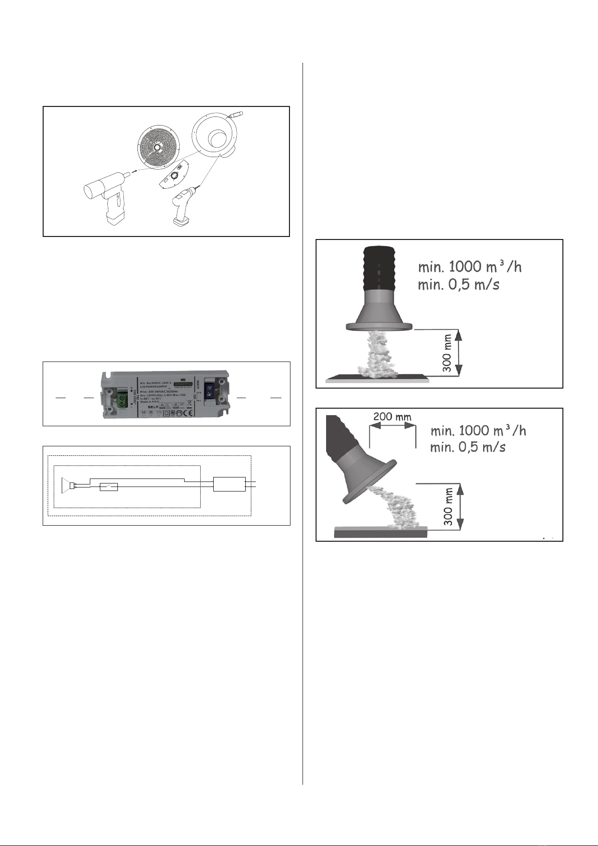
Do not dismantle any factory-mounted parts,
since it impedes the commissioning of the
equipment.
An authorised electrician must carry out all
electrical installations.
1.1 Danger
Explosive media – The Extraction arm is not suitable
for the extraction of aluminium dust, our, textile dust
nor for sawdust or other media, which are connected
with danger of explosion, without specic approval from
Geovent A/S.
Placing the hand between the spring and the carrying
arm could involve a risk of mutilation.
Demounting the spring is deadly dangerous.
1.2 Field of application
The COMPACT arm is the ideal Extraction arm for the
extraction of welding smoke, grinding dust, fumes,
etc. when there is only limited space available in the
working area.
Since the arm is telescopic, it only requires minimum
space, and still it is a perfect combination between the
large arms with major suction capacity and the smaller
arms, which are easy to position.
The Extraction arm is not suitable for the extraction of
aluminium dust, our, textile dust nor sawdust or other
media, which are connected with danger of explosion,
without specic approval from Geovent A/S.
Under no circumstances may the balancer, which
is mounted on the ceiling bracket, be loosened or tigh-
tened to the extent that the inner spring breaks. There-
fore, be careful in order to avoid loading the spring in
the outer areas.
The hose may be damaged and leaky via outer loads,
e.g. by a screwdriver. Avoid such load in order to safe-
guard a long life.
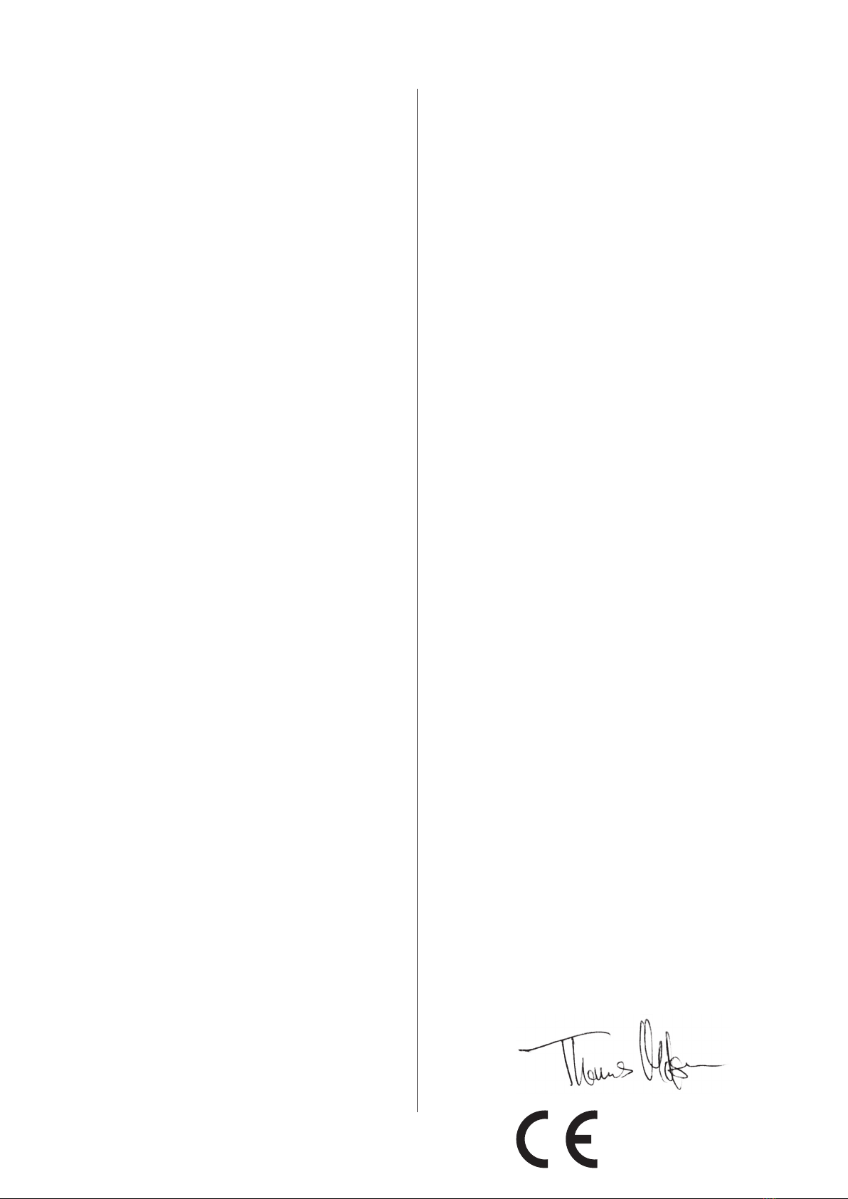
1.3 Technical data
Recommended ow area
Hose dimension:
Ø160 800-1000 m³/h
Ø200 1000-1500 m³/h
Length: 1-2 and 1,5-3 m
Via an extension arm up to: 7 m
Hose Max. Temp. (depends onthe type) Up to 150°C
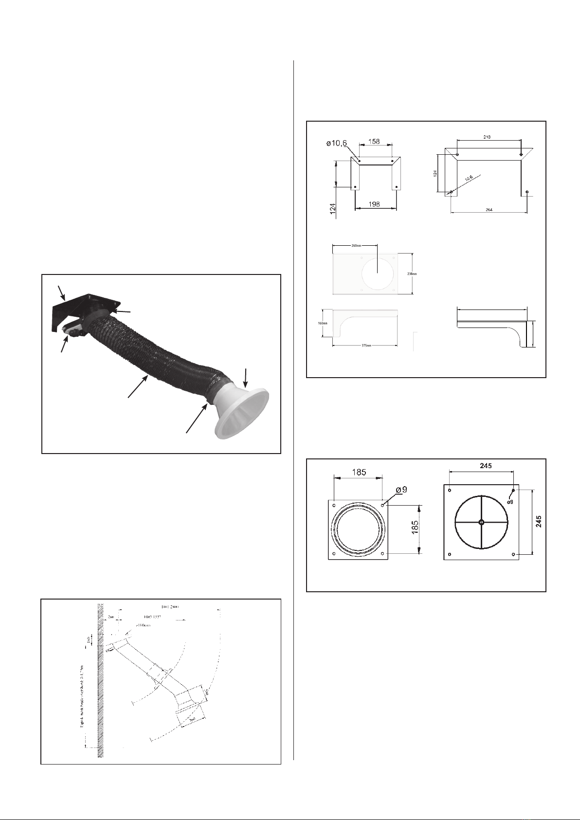
1.4 Construction
Ceiling bracket: Powder enamelled in black RAL 9005
steel bracket, the rotary joint of the bracket can rotate
360°.
Hood: The light-weight aluminium hood ø160 or ø200
mm is equipped with an integrated handle.
The hood is powder enamelled in RAL 1007.
May be rotated in all possible positions.
Contents
1.0 General safety precautions.................. 3
1.1 Danger .................................3
1.2 Field of application . . . . . . . . . . . . . . . . . . . . . . . . 3
1.3 Technical data............................ 3
1.4 Construction – table of dimensions ........... 3
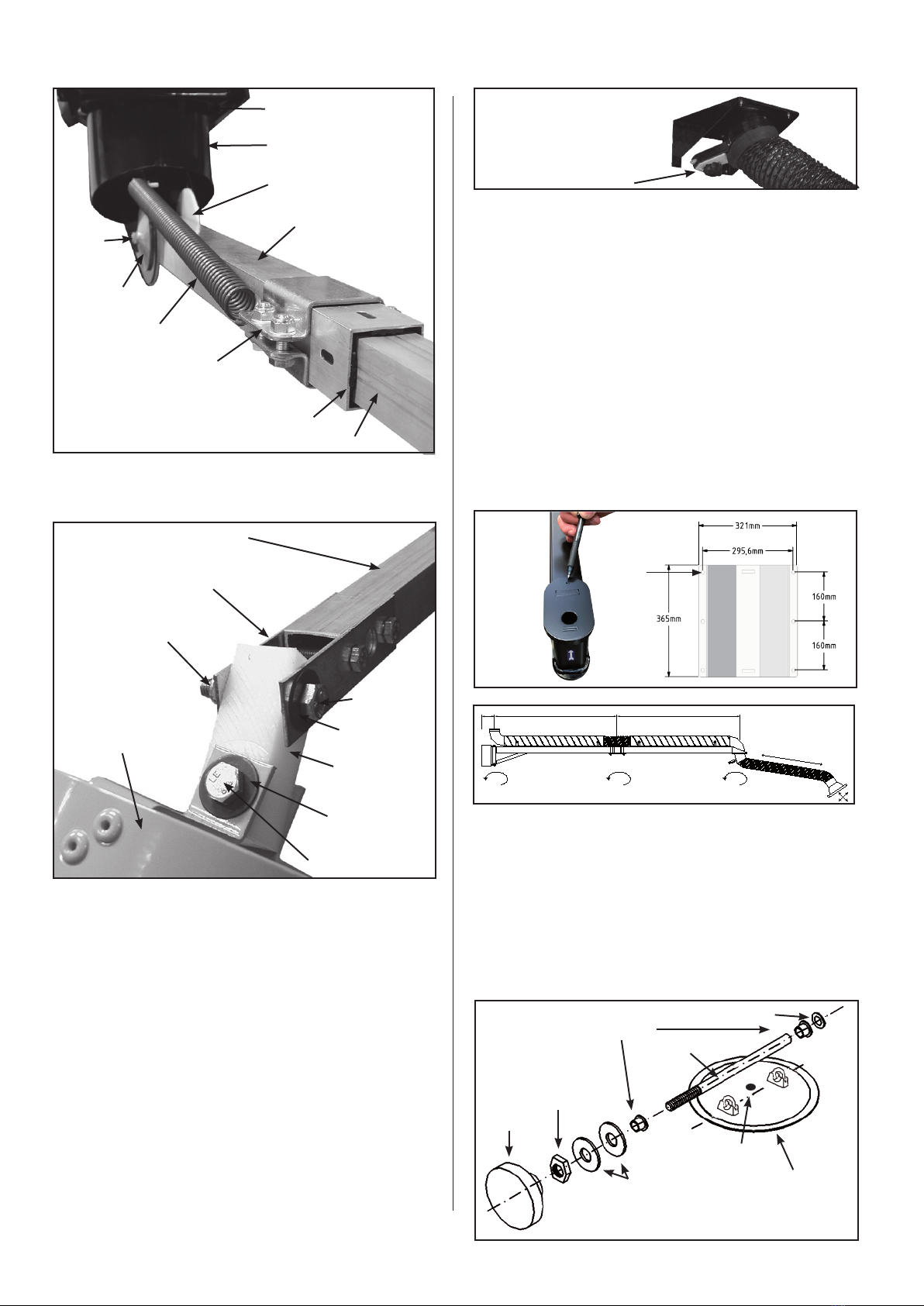
2.0 Installation .............................. 4
2.1 Optional equipment ....................... 5
2.2 Connection ..............................5
2.3 Trial run – exact adjustment ................. 5
3.0 User instruction – application ................ 5
4.0 Maintenance.............................6
5.0 Liability . . . . . . . . . . . . . . . . . . . . . . . . . . . . . . . . . 6
6.0 Declaration of conformity ................... 7
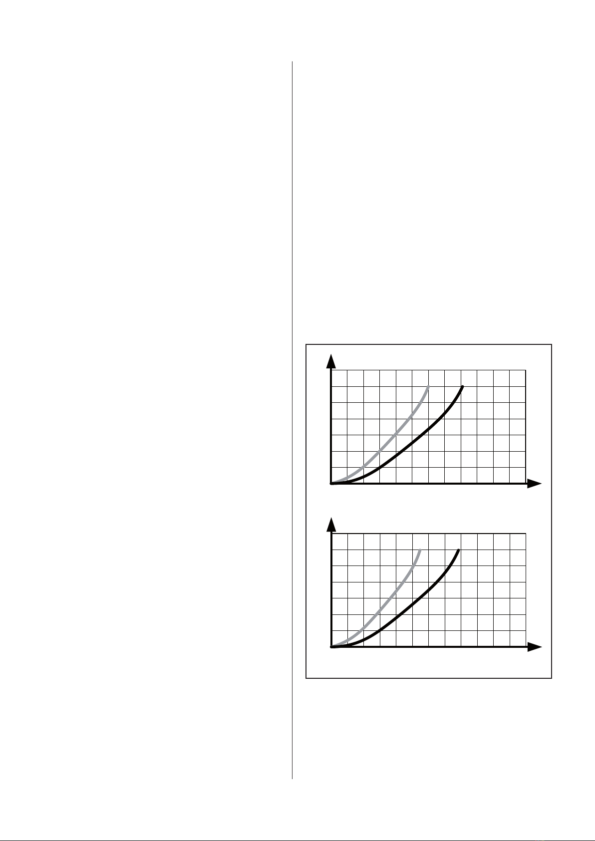
200
200
Volumenstrøm [m³/h]
[Pa] COMPACT arm 1,5-3m Tryktab
400 600 800 1000 1200 1400 1600 1800 2000 2200
400
600
800
1000
1200
1400
ø160 ø200
200
200
Volumenstrøm [m³/h]
COMPACT arm 1-2m Tryktab
400 600 800 1000 1200 1400 1600 1800 2000 2200
400
600
800
1000
1200
1400
ø160 ø200
COMPACT arm 1-2m Pressure drop
COMPACT arm 1,5-3m Pressure drop
Airow (m³/h)
Airow (m³/h)