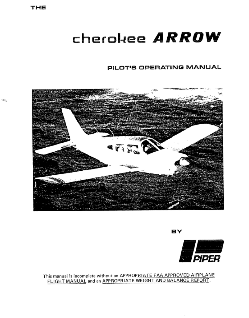
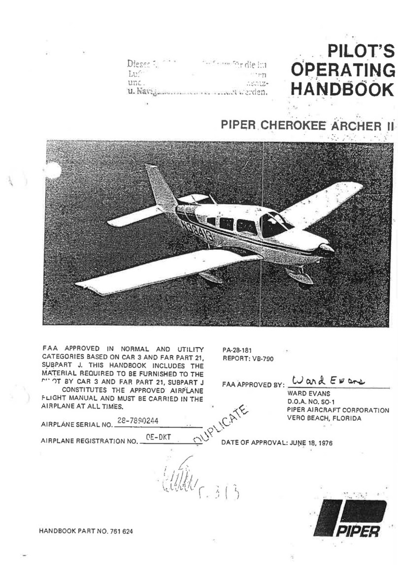
Piper CHEROKEE ARCHER User manual

_,,
··~--
~
-·
·
·•
"
~
·
~
l _
_,/
THE
cherol-lee
ARCHER
PILOT'
S
OPERATING
MANUAL
BV
This manual
is
incomplete without
an
APPROPRIATE
FAA
APPROVED AIRPLANE
FLI
GH
T
MANUAL
and an APPROPRIATE
WEIGHT
AND
BALANCE
REPORT.

28-7505222 N1185X
,~~~PR75UTZff~~
1-20-75

TABLE
OF
CONTENTS
GENERAL
SPECIFICATIONS
DESCRIPTION
&
AIRPLANE
MANUAL
EMERGENCY
PROCEDURES
WEIGHT
AND
BALANCE
LOADING
INSTRUCTIONS
OPERATING
INSTRUCTIONS
OPERATING
TIPS
PERFORMANCE
CHARTS
HANDLING
AND
SERVICING

APPLICABILITY
This manual
is
applicable to Piper Model PA-28-180 aircraft having serial
28-7405001 through 28-7505259. Contact Piper Customer Services for specific information on
the application
of
this manual.
REVISIONS
The information in the Pilot's Operating Manual will current revisions
distributed
to
the airplane owners.
material will consist
of
necessary to the text
manual
and/or
to
add information
to
cover added airplane
I. Revisions
L
II. Material
Black lines will current revisions with changes and
of
text and illustrations. Changes in capitalization,
location
of
material
on
a page will
not
be identified by symbols.
Ill. Original Pages Issued
The original pages issued for this manual prior
to
revision are given below:
1-1
through 1-3,
2-1
through 2-18,
3-1
through 3-18,
4-1
through 4-6,
5-1
through 5-27,
7-1
through 7-10,
8-1
through 8-2,
9-1
through 9-10,
10-1through10-15.
iii

iv
OPERA
TING MANUAL LOG
OF
REVISIONS
0 Air Conditioner
Airplane Performance.
7-11
Added
7-12 Added page.
8-1
Revised item 6.
ii
Added
PAC
Approval Form.
2-9a
l
2
6
AF/M
W/B
7-4
8-1
Added Applicability and Item III.
...
nii;u••'"
Pages Issued.
Added l
to
Rev. 2
to
AIRCRAFT
DELIVERED WITH
MANUALS
PRIOR
TO
THIS REVISION
DO NOT
REQUIRE
THIS REVISION.)
Added
footnote.
Added page (added material from page 2-8).
Relocated page (Alternator-Starter
Schematic).
Added page (Alternator-Starter Schematic).
Added Annunciator Panel information and
footnote.
Revised Instrument Panel illustration.
Added Seat Removal instructions.
Added Rev. 2
to
Report: VB-558.
Added Rev. 3
to
Report· VB-547.
Added Annunciator Panel check
to
Warm-
up and Ground Check; added footnote.
Revised item 6; added footnote.
Relocated material from page 8-1.
l

PILOT'S
OPERATING
MANUAL LOG
OF
REVISIONS
(1.:ont)
Revi'iion Revised
Description
Da
tl'
Pages
Rev. 3
(cont)
9-i Revised
Performance
Charts
Index.
9-2 Revised
Takeoff
Chart.
9-3 Revised
Climb
Chart.
9-4 Revised Range
Chart.
9-5 Revised Engine
Chart.
9-6
Revised Airspeed
Chart.
9-7 Revised Stall Speed vs Weight
Chart.
9-8 Revised Stall
Speed
vs Angle
of
Bank
Chart.
9-9 Revised Glide
Chart.
9-10
Revised Landing
Chart.
l0-11 Revised
Battery
Service.
Rev. 4 - 761
556
1-2
Added
0-360-A4M
engine
designation
and
Jan.
20, 1975
(PR750120)
footnote.
2-1
Added
0-360-A4M
engine
designation
and
footnote.
AF/M
Added
Rev. 3
to
Report:
VB-558.
W/B
Added
Rev. 4
to
Report:
VB-547.
7-4
Added
new
item
9.;
revised
existing
item
nos.
under
TAKEOFF.
7-8 Revised ELT info.
8-2
Added
item
11.
I 0-8
Added
0-360-A4M
engine
designation
under
Oil
Requirements.
Rev. 5 - 761
556
iii
Added
concluding
ser. no.
to
Applicability. Nov. 21, 1975
(PR751121)
l -l Revised Cruise
Speed
and
Range figures;
revised
Empty
Weight
and
Useful
Load;
deleted
footnote.
1-2
Deleted
footnote.
2-1
Revised
Airframe
info;
deleted
footnote.
A
F/M
Added
Rev. 4
to
Report:
VB-558.
W/B
Added
Rev. 5
to
Report:
VB-547.
8-1
Revised item 8
(Fuel
Warning Tip).
9-4 Revised Cruise
Performance
-Range
chart.
9-6 Revised Cruise
Performance
-
True
Airspeed
chart.
Re\.6-761556
2-8
Added
Warning.
March
26, 1979
(PR
790326) 2-8a
Added
info.
2-14
Added
Caution.
WiB
Added
Rev. 6
to
Report:
VB-547.
7-2 Revised items.
7-8, 7-9 Revised
ELT
info.
iv-a

OF
REVISIONS
Date
March
16,


CHEROKEE
ARCHER
GE'NERAL SPECIFICATIONS
PERFORMANCE
Published are for standard airplanes flown at gross weight under standard
conditions at sea unless otherwise stated. Performance for a specific airplane may vary
from published depending
upon
the equipment installed, the condition
of
engine,
airplane equipment, atmospheric conditions and piloting technique. Each performance
figure below
is
subject
to
the
same conditions as
on
the corresponding performance chart from
which it is taken
in
the Performance Charts Section.
Takeoff
Ground
Run, 25 ° flaps, sea level
(ft)
Distance Over 50-ft Obstacle, 25° flaps, sea level
(ft)
Best
Rate
of
Climb Speed
(mph)
Rate
of
Climb
(ft
per min)
Best Angle
of
Climb Speed, sea level
(mph)
Max sea level
(mph)
Optimum Altitude
9300
ft,
75'Yo
power (TAS) (mph)
(
(ft)
at best power mixture
(mph)
power.
2,800
ft
power.
14,000
ft
Range at best power mixture (mi)**
power,
9300
ft
power, l 2,800 ft
at best economy mixture (mph)
power,
9300
ft
power, 12,600 ft
Range
at
best economy mixture (mi)**
pOWl.)L
9300
ft
12.600 rt
down (CAS) (mph)
up
(CAS)
(mph)
Landing sea level, flaps down (ft)
Distance Over 50-ft Obstacle, sea level
(ft)
are with optional wheel fairings installed. Subtract 3
mph
if wheel
WEIGHTS
Gross
Standard
I Wl'iglil (lbs)
Maximum Useful Load (lbs)
GENERAL
SPECIFICATIONS
REVISED: NOVEMBER 21, 1975
720
1625
85
725
76
148*
141*
14,150
16,500
132*
125*
705
131*
123*
715
774
61
68
11
2450
1404
1046
1-1

O-J60-A4A
I
00
6.00
(i.()()

12'
I0.511"
30"
63"
32'
2.50"
24'
00"
. /

DESCRIPTION
AND
2-15
6

THE
AIRPLANE
defrosting.
DESCRIPTION
AIRPLANE AND SYSTEMS
propeller
is
AIRPLANE AND
SYSTEMS
REVISED: NOVEMBER
2t,
1975
CHEROKEE ARCHER
2-1

Main Wheel Assembly
2-2
AIRPLANE
AND
SYSTEMS
ISSUED: JULY 9, 1973


CHEROKEE ARCHER
Console
FLIGHT CONTROLS
Dual controls are provided as standard equipment, with a cable system used between the
controls and the surfaces. The horizontal tail (stabilator) is
of
the
all-movable slab type with a
trim tab
mounted
on
the
trailing edge
of
the stabilator to reduce
the
control system forces. This
tab
is
actuated
by
a
control
wheel
on
the
floor between the front seats.
The stabilator provides extra stability
and
controllability with less size, drag and weight
than conventional tail surfaces. The ailerons are provided with a differential action which tends
to
reduce adverse yaw in turning maneuvers, and which also reduces
the
amount
of
coordination
required
in
normal turns. A rudder trim adjustment
is
mounted
on
the right side
of
the pedestal
below the
throttle
quadrant
and permits directional trim
as
needed in flight.
The flaps are manually operated, balanced for light operating forces and spring-loaded to
return to the up position. A past-center lock incorporated in the actuating linkage holds the flap
when
it
is
in
the up position so
that
it may be used
as
a step
on
the
right side. The flap
will
not
support a step load except when in the full up position, so
it
must
be
completely retracted when
us
ed
as
a step. The flaps have three extended positions, l0, 25 and
40
degrees.
2-4 AIRPLANE AND SYSTEMS
ISSUED: JULY 9, 1973
•
•

··.
~
.
-~-.
\
AIRPLANE
AND
SYSTEMS
ISSUED:
JULY
9,
1973
CHEROKEE ARCHER
Throttle Quadrant and Console
2-5

CHEROKEE ARCHER
----------------
·
-----
·
-------------------
-;
-.
...
~
-
_:
.:;.
:--
:::
.-
-·
,_
----
Fuel Selector
FUEL
SYSTEM
Fuel
is
stored in
two
twenty-five gallon
(24
gallons usuable) tanks which are secured
to
the
leading edge structure
of
each wing
by
screws and
nut
plates. This allows easy removal for
service
or
inspection.
TI1e
fuel selector
control
is
located on
the
left side-panel, forward
of
the
pilot's seat. The
button
on the selector cover must be depressed
and
held while the handle
is
moved to the
OFF
position. The
button
releases automatically when the handle
is
moved back
into
the ON
position.
An auxiliary electric fuel
pump
is
provided
in
case
of
failure
of
the engine driven pump.
The electric pump should be
on
for all takeoffs and landings, and when switching tanks. The
pump
switch
is
located in the switch panel above the
throttle
quadrant.
Each ta
nk
has an individual quick drain located
at
the
bottom
, inboard rear
comer
, and
should be drained to check for water before each flight (a special c
ontain
er is furnished for this
operation). The fuel strainer, which
is
also equipped with a quick drain,
is
located on the front
lower left corner
of
the
fire wall. This strainer should be drained regularly to check for water
or
sedime
nt
accumulation. To drain the lines from the tanks, the tank selector valve must be
switched to each
tank
in turn, with
th
e electric
pump
on, and the gascolator drain valve opened.
(R
ef
er to the Handling and Servicing Section for the complete procedure.)
Fuel
quantity
and
pressure are indicated on gauges located in a cluster on the left side
of
the instrume
nt
panel.
An optional engine priming system
is
available to facilitate starting. The primer pump
is
located
to
the immediate left
of
the
throttle
quadrant.
2-{)
AIRPLANE AND SYSTEMS
ISSUED: JULY 9, 1973

FUEL
QUANTITY
GAUGES
FUEL
TANK
SELECTOR
VALVE
MAIN
TANK
AIRPLANE AND SYSTEMS
ISSUED: JULY 9, 1973
FUEL
PRESSURE
GAUGE
CARBURETOR
Fuel System Schematic
CHEROKEE ARCHER
MAIN
TANK
ENGINE
FUEL
PUMP
ELECTRIC
FUEL
PUMP
2-7

WARNING
when flying
through
overcast
...,.,.,.,
....
'"""'"""
light
can
spacial
msonem.anon.
close
proximity
to
ground,
during
'4master
switch.,.
hereafter this manual both the
"'BAT" alternator side "ALT" are
to
be depressed simultaneously to OFF or
ON
as
directed.
nos.
7505001
and
up
AIRPLANE
AND
SYSTEMS
REVISED:
MARCH
26, 1979
Table of contents
Other Piper Tools manuals

Piper
Piper PA-32-301 Saratoga User manual

Piper
Piper Cherokee Arrow II PA-28R-200 1973 User manual

Piper
Piper CHEROKEE ARROW III Quick setup guide

Piper
Piper SEMINOLE PA-44-180 User manual

Piper
Piper CHEROKEE ARROW 200 User guide

Piper
Piper TWIN COMANCHE PA-30 User manual

Piper
Piper PA-32-301 Saratoga User manual

Piper
Piper PA-34-200T Seneca II User manual

Piper
Piper Archer III PA-28-181 User manual

Piper
Piper Cherokee Archer II Owner's manual