7
©
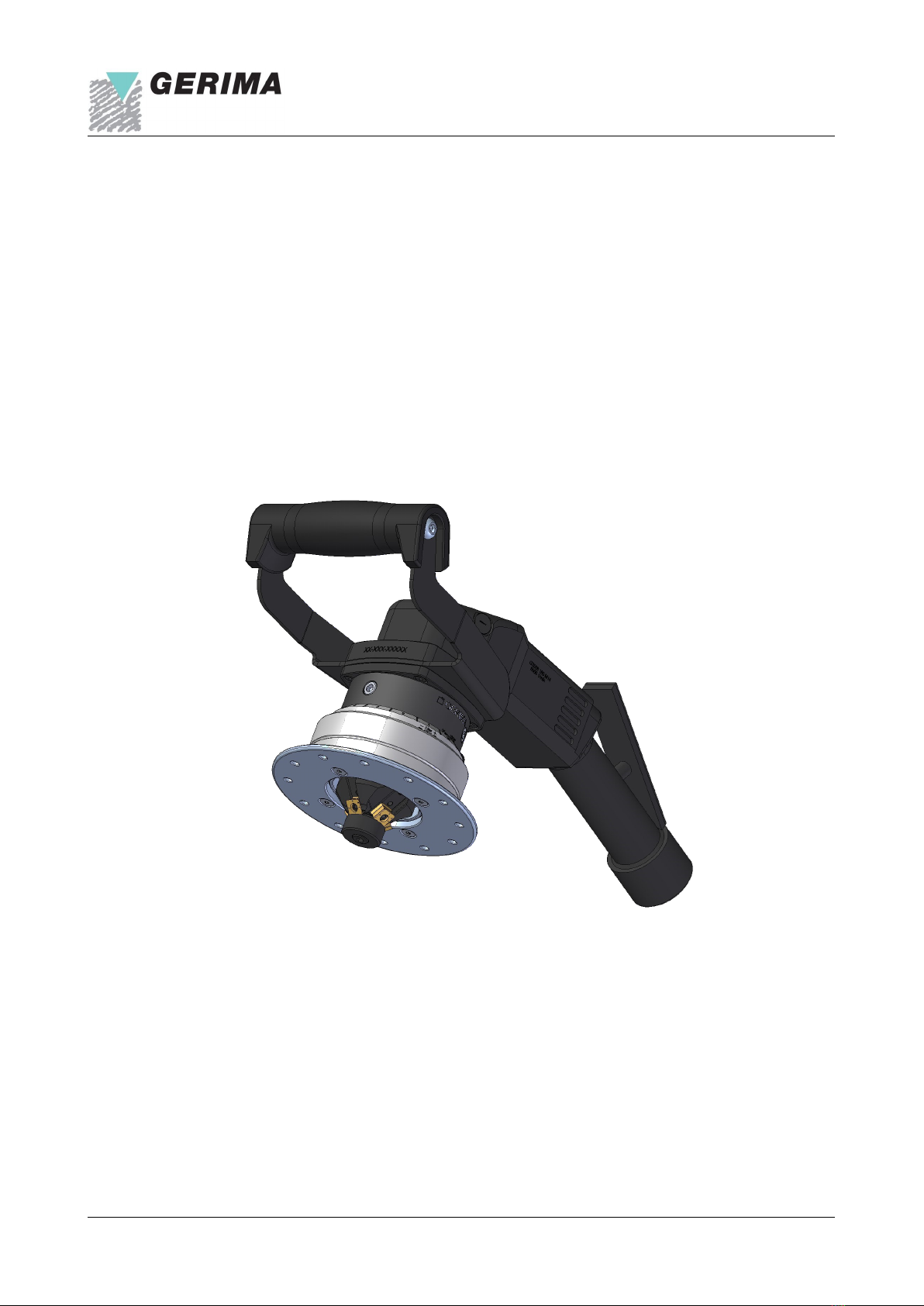
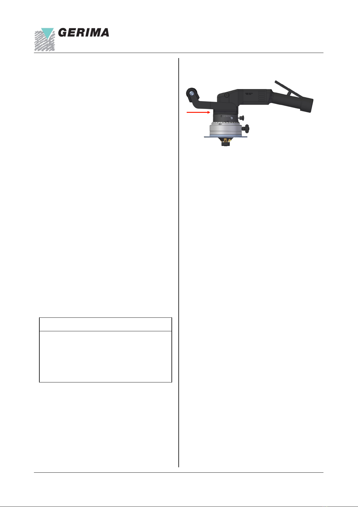
SMA 40 APV-48.H1 / 01.01.2021 / V01.00-EN
Technical manual
Noise emission values in accordance with the DIN
EN 60745-1 standard:
Vibrations:
Note:
The measured values listed above depend on the
materials and operating procedures used and may
therefore be exceeded under other operating
conditions.
Using the machine to create bevels with a width
greater than that permitted will result in a
disproportionally large reduction in the machine’s
on-time and the service life of the indexable carbide
inserts. The vibration and noise emission values
will increase accordingly.
To prevent overloading the machine and to avoid
operator fatigue it is very important to observe the
maximum power-on periods especially when
machining wide bevels or high-strength materials.
Value Un-
certainty
Noise emission [dB (A)]
Emission sound pressure
level LpA 89 3
Peak emission sound pres-
sure level at workplace
(during milling operation)
LpGpeak 105 3
Sound power level LWA 100 3
Total vibration value
(tri-axial vector sum) Appropriate to
DIN EN 60745:
Measured vibration emission
value
ah = 3,0 m/s²
Work process:
- 30° milling head
- 5 mm bevel width (C) in
12 mm steel sheet S 355 Uncertainty
K = 1,5 m/s²
Power-on time (POT):
To avoid damaging the machine, it is essential to
be monitor how long the machine has been
operating continuously (‘power-on time’).
The compressed air that powers a pneumatic drive
also serves to cool the motor as well. Pneumatic
tools can therefore be operated for longer periods
than electrically powered tools.
However, if the machine is subjected to particularly
extreme loads (e.g. when machining wide bevels or
very hard or tough materials) and/or if the machine is
run for very long periods, the air cooling may still be
insufficient to prevent overheating of the milling drive
unit. If the operator continues to use the machine,
the milling drive unit may overheat and be damaged
as a result.
(C=bevel width, POT=power-on time)
The power-on time is always expressed as a
percentage of one hour.
Example:
If the power-on time is specified as 50 %, then you
can use the machine to mill bevels for a maximum of
30 min. in an hour and must then leave the machine
to cool for 30 min.. If the machine is subjected to
heavy loads, the power-on time might be 20 %,
which means it can be used for 12 min. in any hour
and must be left to cool for 48 min.. Before
completely switching off the machine, we
recommend running the machine for one or two
minutes in idle mode (unloaded) so that fan can
continue to draw cool air through the machine.
Do not overload the machine!
The machine can become overloaded if, for
example, it continues to be used even though the
bevel being cut is too large for the material being
milled, or if the cutting inserts have become blunt
and therefore unable to penetrate the material.
Such conditions can lead to large machine vibrations
or even machine breakdown.
To prevent this sort of damage when milling large
bevels and/or hard materials, never try to machine
the bevel in a single pass, always use multiple
passes, and do not forget to change the carbide
inserts before they become blunt or worn.
Material strength C max. POT max.
Aluminium, copper, brass 20mm 80%
Steel up to 400 N/mm² 15mm 60%
Steel up to 600 N/mm² 15mm 50%
Steel up to 900 N/mm² 15mm 40%
Stainless steel 8mm 40%
Total vibration value
(tri-axial vector sum) Appropriate to
DIN EN 60745:
Measured vibration emission
value
ah = 6,0 m/s²
Work process:
- 30° milling head
- 8 mm bevel width (C) in
12 mm steel sheet S 355 Uncertainty
K = 1,8 m/s²