Germid HK-0353535 User manual

Designed in Grand Rapids MI, USA Assembled in China
Multiple Display Rear View Mirror Monitor
User manual
HK-0353535
ECER10
Approval No.: 10R-03 12762
ECER46
Approval No.: 46R-04 0019
L M R

User Manual
Welcome to use our three display ultra high brightness Rearview mirror monitor.
●We reserve the final explanation right on this User Manual.
●Specifications are subject to change without notice. Sorry for any inconvenience
caused!
●Please make a copy of the important data. We assume no responsibility for the data
loss.
●This manual has been carefully checked. Please contact our service center when any
typing mistake is found.
●Please read the operating instruction carefully and use the accessories only
provided by the original factory to avoid any unexpected damage. No warranty will
be executed if you are not following the instruction or connecting with the
incompatible accessories, we assume no responsibility for any loss and damage
caused hereby.
●Any discrepancy between the pictures with real products hereinafter, the real one
prevails.
●Working voltage of the rearview mirror ranges from 10V to 30V, so a truck with 24V
can install the mirror directly. The mirror does not supply power for camera,
concerning camera power supply range, please refer to corresponding camera
manual. We advise users buy a 24V camera or buy a camera power adapter for
voltage conversion if users install the mirror to a big truck.

Chapter one: Product Information
1.3 Specification
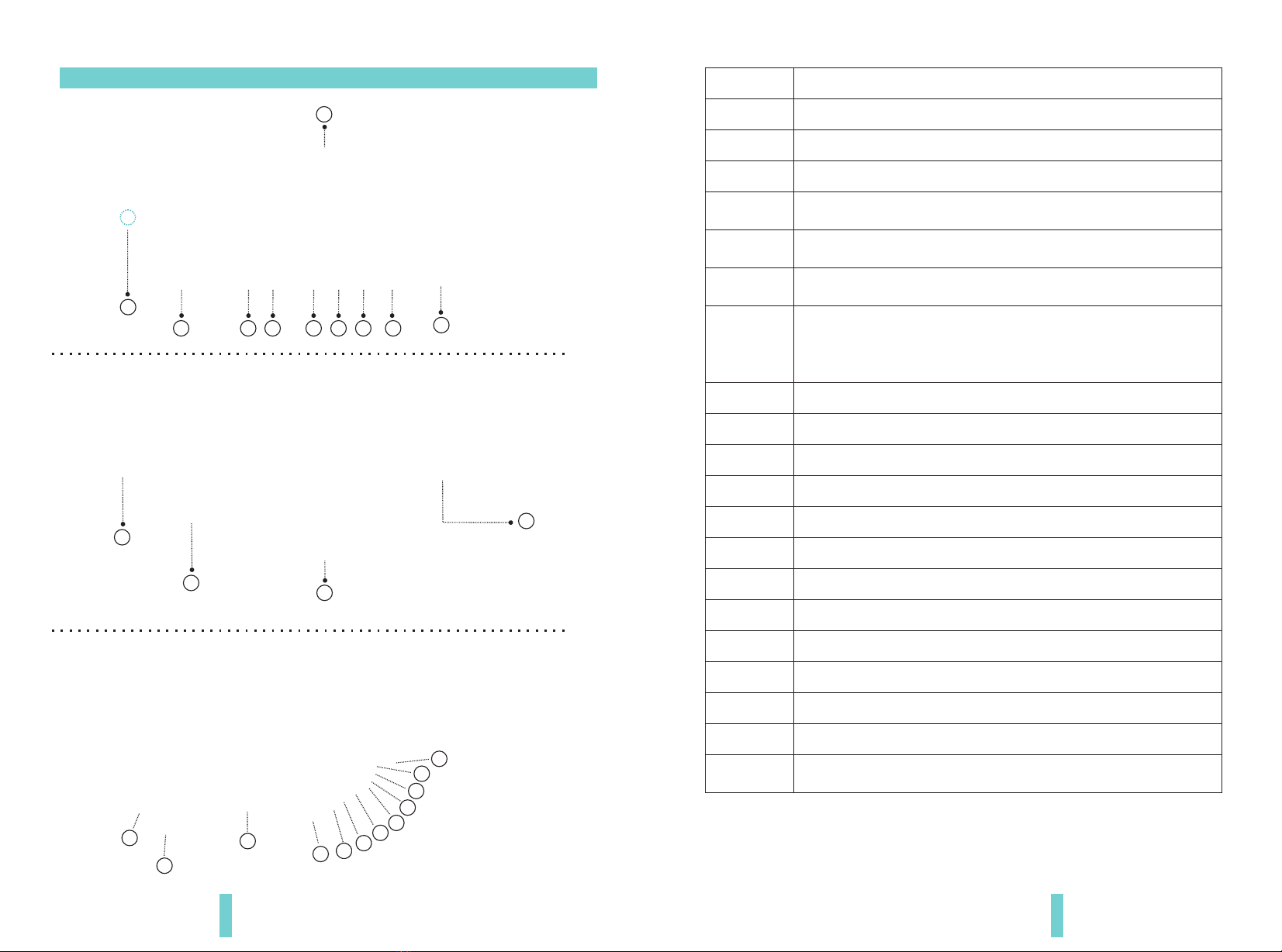
The packing contains the following accessories, please confirm:
Three display rearview mirror monitor
Wire set
User manual
Wire cover
Remote control (option)
For the items listed above, please check with your package box. If any missing or
damage, Please contact with the distributor or the agent as soon as possible.
1.1 Package
●
●
●
●
●
1.2 Features
●
●
●
●
●
Chapter one: Product Information ...................................1
1.1 Package................................................1
1.2 Features...............................................1
1.3 Specification............................................1
1.4 Keyboard ..............................................2
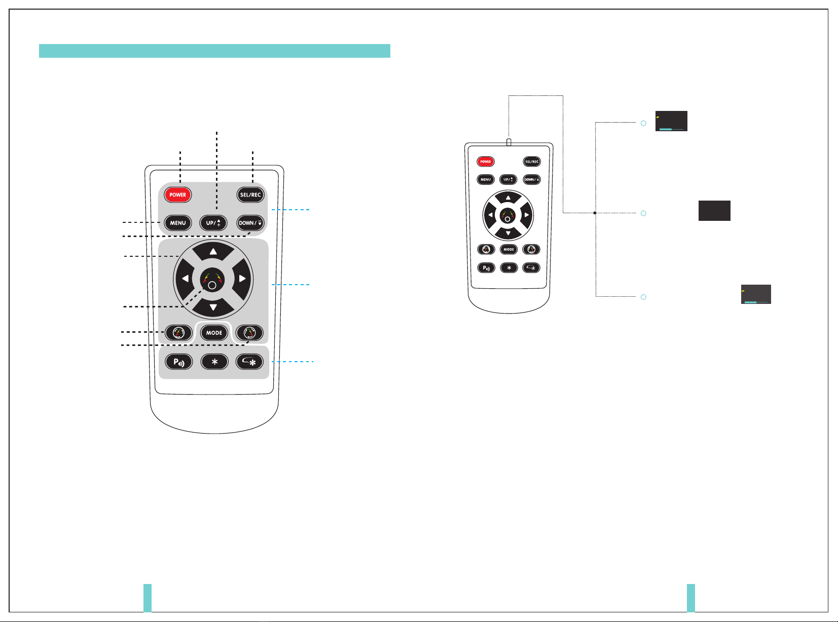
1.5 remote control..........................................4
Chapter two: Installation and wiring. . . . . . . . . . . . . . . . . . . . . . . . . . . . . . . . . . 6
2.1 How to install mirror monitor. . . . . . . . . . . . . . . . . . . . . . . . . . . . . . . 6
2.2 Special bracket..........................................7
2.3 How to wire ............................................8
2.4 How to display the rear view mirror screen . . . . . . . . . . . . . . . . . . . 10
Chapter Three: Basic functions.....................................11
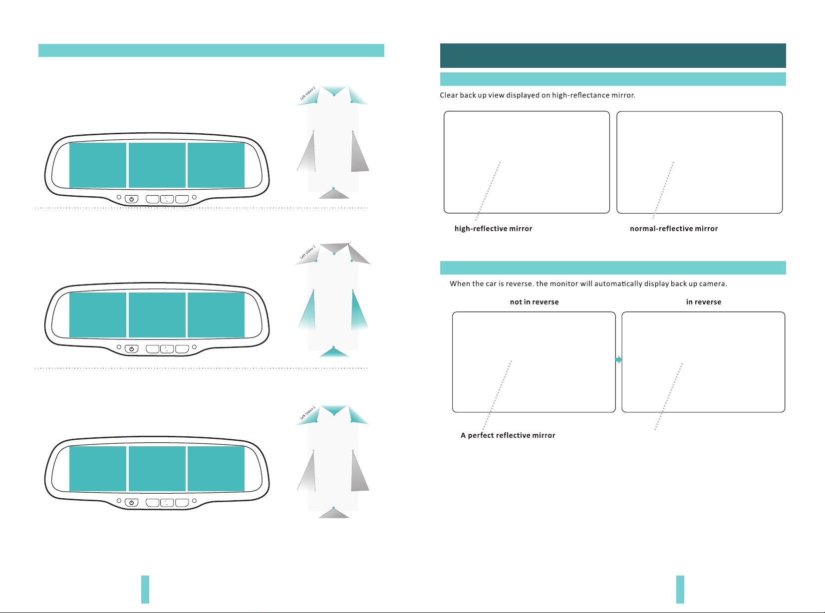
3.1 High-reflectance Mirror..................................11
3.2 Back up Camera Display..................................11
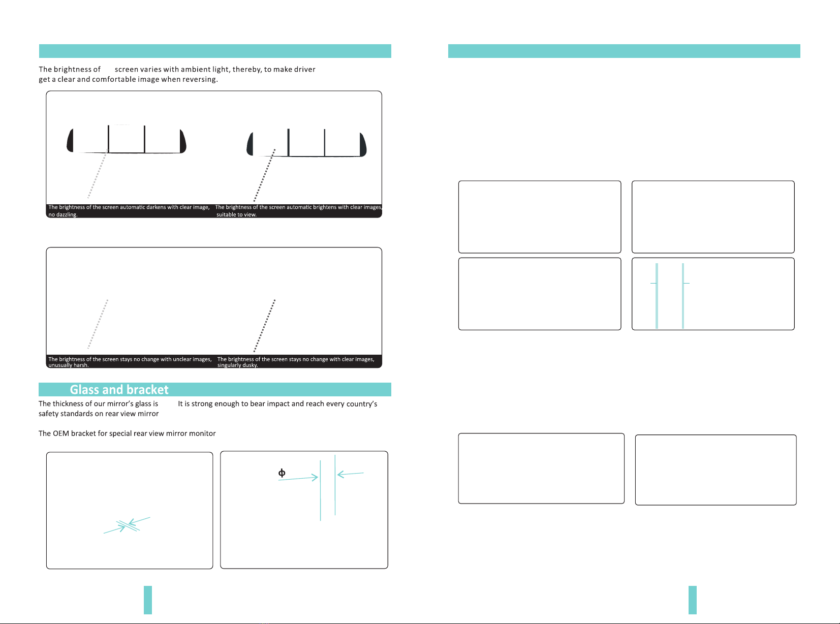
3.3 The Brightness of Screen Automatically Adjust . . . . . . . . . . . . . . . . 12
3.4 Glass and bracket ......................................12
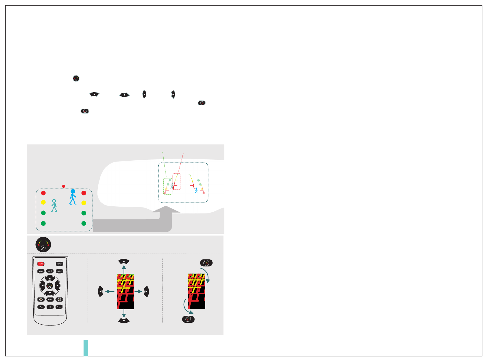
3.5 Adjustable guide line(the function just for middle screen) . . . . . . . 13
Support backup camera display
Support auto dimming function(option)
Auto brightness adjustment
Three 3.5 inch screens display, 6 video +1 audio input
Support infrared operation
MCU
FLASH
LED display
button
remote control
backup camera display
original car signal detection
working voltage
working current
standby current(turn off screen)
relative humidity
barometric pressure
storage temperature
working temperature
TW8825/MST706
MX25L6445E/2NF40A
320*240 RESOLUTION
MCU extension button
infrared receiver signal
processed by MCU
CVBS video input circuit
0%-90%
86Kpa-106Kpa
-1352℉~+2873℉
-676℉~+2535℉
supply 13V:670±10MA
supply 24V:340±10MA
supply 13V:135±10MA
supply 24V: 70±10MA
DC 10V-30V
system detects trigger signal,
and make corresponding control.
PAL/NTSC auto identification
4 mm glass and car factory OEM bracket
●

2 3
1.4 Keyboard
1
0
Infrared receiver window
Light sensor
2 3 4 5 6 7
3.5 inch ultra high brightness display screen
8
Lightsensor
Connector(connectwithmaincable)
SpecialBracket
12
0
2
3
4
5
6
7
8
10
11
12
14
16
17
13
14
15
16
17
18
Red wire to +12V
BlackwiretoGND
Video input
Turn on/turn off video display screen
9
3.5 inch ultra high brightness display screen
9
15
18
20 21
22
23
24
25
25
Control line (for further extension function)
Brake detection signal line
Reverse detection signal line
3.5 inch ultra high brightness display screen
1
10
11
13
19
5 pins connector
19-24
Start the car-default display FL video-short press to switch RL video-short press
again to turn off screen-enter standby state-short press to continue the cycle
(please refer to the page 10 of this menu.)
Start the car-default display FM video-short press to switch RM video-short press
again to turn off screen-enter standby state-short press to continue the cycle
(please refer to the page 10 of this menu.)
Start the car-default display FR video-short press to switch RR video-short press
again to turn off screen-enter standby state-short press to continue the cycle
(please refer to the page 10 of this menu.)
Rearview mirror without auto dimming: when turn off screen or no video signal
input, the indicator will light on, otherwise it will be off.
Rearview mirror with auto dimming: when auto dimming is working, the indicator
will light on, otherwise it will be off.
Audio control line: trigger line enter reverse mode or manually press”M” to enter
RM video, then audio function starts.
Remark: BOYO may make changes to specifications and product descriptions at any time for any reason.

As shown above on operation of left screen, press “MENU” to bring up PICTURE
and set menu options. On this state, press “SEL /REC” then select sub-menu to
settings, available options can be set including, BRIGHTNESS, COLOR,
LANGUAGE. Press again after setting “MENU” to make “SYSTEM” preference
settings, options can be set only“PRESET”.
If you want to operate right screen by remote control, press”POWER” button.
Right screen works with remote control. Relevant operation is same as left
screen.
If you want to operate the middle screen by remote control, press “POWER”
button,. Middle screen works with remote control. It should be noted that in
the middle screen of PICTURE there are additional NIGHT BRIGHT option.
SYSTEM menu can be set including VOLUME, SCALE, LANGUAGE, PRESET.
4 5
PICTURE
BRIGHT
CONTRAST50
COLOR
LANGUAGEENGLISH
50
50
PICTURE
BRIGHT
CONTRAST50
COLOR
LANGUAGEENGLISH
50
50
PICTURE
BRIG HTNESS
CONTRAST50
COLOR
NIGHTBRIGHTN.00
50
50
FM FR
FL FM FR
FL FM
Note:RCD means Rear Camera Display
Not Applicable for
VTM35x3
Adjust parking line
Menu operation
Parking line clockwise rotation
Switch screen items when setting the menu Select button
Up button
Menu button
Parking line rotate CCW
Adjust parking line for every
direction: up and down, left and right
Activated the adjustable parking line
/switch from left to right line
Down button
1.5 remote control

2.1 How to install irror monitorm
Remove the original rear view mirror and remain
the metal base on the windscreen
Original car rear view mirror
Along this direction
to install rearview mirror Along this direction
to install rearview mirror
Along this direction
to install rearview mirror
contrarotate the fixed
rearview mirror
We have many kinds of brackets. one of them must suitable for your car, and we are
not going to go through everyone of them, because the space is limited on this
page.
If you don’t find the same bracket here as your car, please contact us for more
brackets option.
2.2 Special bracket
6 7
NO 1: TOYOTA CAMRY
FORD FOCUS
MAZDA-6
NO 2: HONDA ACCORD
CIVIC
MITSUBISHI GALANT
NO 32: MOST MITSUBISHI
TOYOTA
MAZDA
NO 7: HYUNDAI
KIA
No42: MOST PEUGEOT
RENAULT
VOLVO
NO 35: MOST BMW
PEUGEOT
NO 3: VOLKSWAGEN PASSAT
JETTA
AUDI-A6-1.8T/A4-1.8T
NO 57: MOST NEW VOLKSWAGEN
NO 33: MOST FIAT
2 1 1 Remove the original mirror. .
2 1 2 Install mirror monitor on the base. .

2.3 How to wire
Connecting method: By linking the green reversing line, the reversing signal
input to the rear view mirror and reversing video can automatically display on
the right side of the screen. (Not connect reversing box)
3M
powerharness
After the product is power on and displays the boot Logo (if in the display logo process, cut reversing signal, then
interrupt boot logo display, enter the reverse mode), in the default standby state, if there is VIDEO signal, the
screen display video view and standby indicator is off. In this state, short press the button
to close or open the screen display.
If it detects the reverse signal, the mirror enter into reverse mode. if there is a reversing camera video signal, the
LCD monitor is turned on, while closing the standby indicator. if there is no back-up camera video signal, then the
LCD monitor is turned off, while the standby light is turned on; Only does the reverse signal disappears, it can exits
CAMERA state, back to VIDEO states. Please note: It is the normal phenomenon there will be a short jump process
when swift the video.
When the mirror is connected to the power firstly during driving, the car monitor is shown in front of the video
image. If the user press button to switch to car rear video images manually, the program will have a memory , and
the car monitor is shown in back of the video image.
In case of sudden emergency brakes, rear video mirror will automatically switch to the car front images to the
behind images of the car. it will automatically return to the car front video after releasing the brake. After exiting
trigger line and returning to working status, the car monitor will return to the video image before triggering.
Recommendation of the
location of camera installation
Left Video 1
Right Video 1
Right Video 2
L MR
Left Video 2
Audio input
Remark: We may made any changes to specifications and productdescriptions at any
time for any reason.
CTR1(blue)
Temporarily vacant
Red to ACC +12V
Black to GND
Recommended to
connect the brake line
CAP-BACK
CTR2(Yellow)
3M
power harness
Black to GND
Red to ACC +12V
RightVideo1
Black to GND
LeftVideo1
Red to ACC +12V
Black to GND
Red to ACC +12V
Black to GND
Red to ACC +12V
RightVideo2
Black to GND
LeftVideo2
Red to ACC +12V
Black to GND
Red to ACC +12V
Middle video 1
Middle video 2
Audio input line
8 9
Reversing
detection signal line
Middle video 1
Middle video 2

L MR
Driving:
Reversing:
Braking:
Left Video 1
(FL)
Right Video 1
(FR)
L MR
Left Video 2
(RL)
Right Video 2
(RR)
(RM)
L MR
Left Video 1
(FL)
Right Video 1
(FR)
3.2 Back upCamera Display
automatically display
FL RM FR
3.1 High-reflectance Mirror
10 11
Left Video 1
Right Video 1
Right Video 2
Left Video 2
Left Video 1
Right Video 1
Right Video 2
Left Video 2
Left Video 1
Right Video 1
Right Video 2
Left Video 2
When the mirror powered, it will display front video on the
screen. Left upper corner of Left screen displays FL( front
left video), left upper corner of middle screen displays
FM(front video), left upper corner of right screen displays
FR(front right video).
When the car is in reverse, Left upper corner of Left
screen displays RL(back left video), left upper corner of
middle screen displays RM(back video), left upper corner
of right screen displays RR(back right video).
If the screen is in open status before braking, FL will be displayed on
the Left screen, FM will displayed on the Middle screen, and FR will
be displayed on the Right screen.
(FM)
Middle video 1
Middle video 1
(FM)
Middle video 1
Middle video 1
Middle video 1
Middle video 1
Middle video 1
Middle video 1
Middle video 1
Chapter Three: Basic functions
2.4 How to display the rear view mirror screen.

FL RM FR FL RM FR
Remark: When reversing, the middle screen display reverse video only, its left and right
screen still show the front video (please refer the button function for details)
3.4
3.5 Adjustable back-up guide line (just working for the Middle screen)
12 13
3.3 The brightness of the screen automatically adjusts
the
.
, it using 21mm thickness pipe.
4mm.
4mm
21mm
Generally, to help drivers estimate the distance from obstacles, there are three lines
for reference -red, yellow and green. Those three lines are displayed on the monitor
when car is reversing. The green line is 3m from the back of car and the yellow line
is 2m. The distant red line is 1m from the backside of car while the closed red line is
0.4m. Both reference lines on the left and right should leave 0.2m space from the
car.
20CM20CM
3.5.1 About guide line
Regular guide line is fixed. But installation sites of cameras are different as well as
car size. The fixed guide line is not accurate enough for drivers. There will be a great
difference between regular and fixed guide lines and car's real guide lines, especially
when camera is mounted on the left or right side of car backside. It may cause
accidents.
3.5.2 What the regular guide line is

UP Clockwise
Down
Right
left
Move the guide line Rotate the guide line
Reverse clockwise
Press the button to choose the L or R adjustable guideline
Remote control
RL
According to the site of standard reference line, we can put reference objects such
as desks in the back area of car. Compared with the marked reference objects, we
can adjust the sites and angle of two guide lines displayed on the monitor. You will
get the accurate and safety guide lines once they coincide with the reference
objects.
Press setting button is to enter into “guide line adjustment” mode. The system is
defaulted to adjust left guide line firstly. Press the button again will switch to adjust
the right guide line. The up , down left and right buttons are to
adjust the correspondent location of guide lines. The clockwise rotation and
contra rotation buttons are to adjust the angle of guide lines. It is easy to
operate and calibrate. After finishing calibration, switch the reverse gear to save
the information.
Caution: keep the remote control 0.5m-1.0m from rear view mirror when you use the remote to
adjust the parking lines.
3.5.3 How to adjust the guide line
14
Wrongposition
Right position
Displayonthemonitor
Table of contents
Other Germid Automobile Accessories manuals
Popular Automobile Accessories manuals by other brands

Voxoa
Voxoa MCU-20A(P40) user manual

Broadfeet
Broadfeet DCNI-523-32 installation instructions

Directed
Directed Directechs DB3 installation guide

E&G Classics
E&G Classics 1045-019U-15B Upper Replacement

Team Tech Offroad
Team Tech Offroad TACOMA HOOD STRUT Kit Installation

Axis
Axis TPMS403 instruction manual