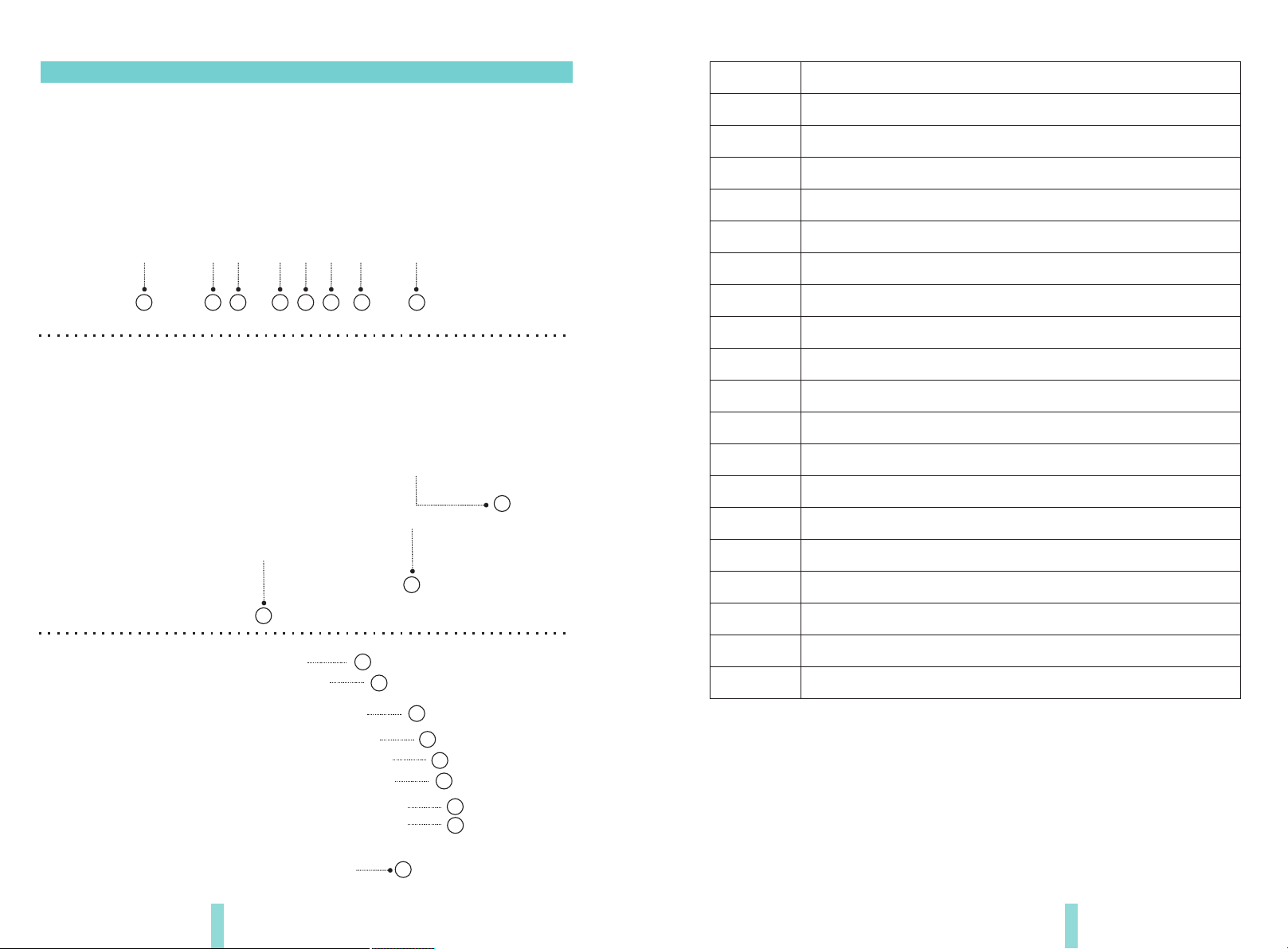
Germid HK-04343LA User manual

Designed in Grand Rapids MI, USA Assembled in China
Car Rear View Mirror with Dual LCD
Display Screens
User manual
HK-04343LA
ECER10
Approval No.: 10R-03 12762
ECER46
Approval No.: 46R-04 0019

Welcome to use our car rear view mirror with dual LCD display screens.
●We reserve the final explanation right on this User's Manual.
●Specifications are subject to change without notice. Sorry for any inconvenience
caused!
●Please make a copy of the important data. We assume no responsibility for the
data loss.
●This manual has been carefully checked. Please contact our service center when
any typing mistake is found.
●Please read the operating instruction carefully and use the accessories only
provided by the original factory to avoid any unexpected damage. No warranty
will be executed if you are not following the instruction or connecting with the
incompatible accessories, we assume no responsibility for any loss and damage
caused hereby.
●Any discrepancy between the pictures with real products hereinafter, the real
one prevails.
●The working voltage of this model is 10V to 30V, and it can be installed in the
truck if its voltage is 24V. Please refer to the camera manual for the camera power
supply, since it's not from the car rear view mirror. The 24V camera is advisable if
installed to truck or purchase the power adapter to convert the voltage.
User's Manual

Chapter one: Product Introduction
1.3 Specification
The packing box contains the following accessories, please confirm:
Dual display rear view mirror monitor
wire harness
User's manual
wire cover
Remote control(option)
For the items listed above, please check with your package box. If any damage,
Please contact with the distributor or the agent as soon as possible.
1.1 Package
●
●
●
●
●
Car rear view mirror with dual LCD display screens
4-way video input
Back up camera display
Automatic brightness adjustment
4.0 mm glass and 23mm car factory OEM bracket
Adjustable guide line (option)
1.2 Features
●
●
●
●
φ
●
●
Screen size: 4.3 inch
Display screen: TFT-LCD
Aspect resolution: 480(H)*272(V)
Working voltage: 10V~30V
Working temperature: -20℃~+75℃
Four ways video input
Signal system: PAL/Auto/NSTC
●
●
●
●
●
●
●
Chapter one: Product Introduction...................................1
1.1 Package................................................1
1.2 Features...............................................1
1.3 Specification............................................1
1.4 Keyboard ..............................................2
Chapter two: Installation and Wiring . . . . . . . . . . . . . . . . . . . . . . . . . . . . . . . . . 4
2.1 How to install ...........................................4
2.2 Special bracket..........................................5
2.3 How to wire ............................................6
2.4 How to display the rear view mirror screen . . . . . . . . . . . . . . . . . . . . 8
Chapter Three: Adjustable Guideline . . . . . . . . . . . . . . . . . . . . . . . . . . . . . . . . . 9
3.1 About guide line.........................................9
3.2 What is the regular guide line . . . . . . . . . . . . . . . . . . . . . . . . . . . . . . 9
3.3 How to adjust the guide line . . . . . . . . . . . . . . . . . . . . . . . . . . . . . . 10
Chapter f : . . . . . . . . . . . . . . . . . . . . . . . . . . . . . . . .our Auto Dimming (option) 11

2 3
1.4 Keyboard
Adjustable the brightness of screen (just helpful for the working screen )
1
4.3 inch ultra high brightness display screen
Front light sensor
2
Turn on/off the dual display screen
3
Left video1→Left video2→Turn off Left screen→Left video1
4 5 6
Indicator
74.3 inch ultra high brightness display screen
8
Rear light sensor
9
Connector (connect with wire harness)
Special bracket
10
11
1
2
3
4
5
6
7
8
9
10
11
12
13
14
15
16
17
18
19
20
12
13
14
15
16
17
18
19
20
Red to +12V
Black to GND
Yellow to brake light
Green to reverse light
Video input
Video input
Video input
Video input
Connector (connect with rear view mirror)
Right video1→Right video2→Turn off right screen→Right video1

2.1 How to install
Remove the original rear view mirror and remain
the metal base on the windscreen
Original car rear view mirror
Along this direction
to install rear view mirror
Along this direction
to install rear view mirror
Along this direction
to install rear view mirror
contrarotate the fixed
rear view mirror
1
We have many kinds of brackets. one of them must suit for your car, and we are
not going to go through anymore examples, because the space is limited.
If you don’t find the same bracket here as your car, please contact us.
2.2 Special bracket
4 5
Chapter two: Installation and Wiring
Different cars have different brackets. It depends on your vehicle maker and manufacturer.
There are many methods to remove the original rear view mirror, however, please don’t force the
mirror off the bracket.
The manufacturer will not be responsible for any damage caused to your car by wrong installation of
the mirror.

2.3 How to wire
3M
6 7
power harness
PUSE
BOX
Black to GND
CTR1(Blue)
Red to ACC +12V
Black to GND
Red to ACC +12V
Black to GND
Red to ACC +12V
Black to GND
Red to ACC +12V
Left Video1
Black to GND
Red to ACC +12V
Right Video1
Left Video2
Right Video2
CTR2(Yellow)
Left Video1
Right Video1
it's advisable to connect the reversing line
The advisable installation
position for camera
Left Video 1
Left Video 2
Right Video 1
Right Video 2
CTR line1 controls left video1 and right video1. Whenever line1 connects to
12~24V direct current, then the left screen and right screen of the mirror
would switch to left video1 and right video1 separately. We advise you to
connect CTR1 to reversing line.
CTR line1 controls left video2 and right video2, which is less preferential
than CTR1. That is, when CTR1 and CTR2 connects to battery at the same
time, then only the two videos(left video1 and right video1) from CTR1 can
be displayed on the LCD monitor. When CTR2 connects to current and the
LCD monitor is off, then the monitor keeps be off. However, when the
monitor is on, the left screen and the right screen would switch to left
video2 and right video2 separately.
it's advisable to connect the reversing line
By connecting the green line, the reversing signal is input to the rear view mirror
and reversing video can automatically display on the right side of the screen. (not
connect reversing box)

2.4 How to display the rear view mirror screen.
Driving: “Left Video1” and“Right Video1” display
8
Left Video 1
Left Video 2
Right Video 1
Right Video 2
Left Video 1 Right Video 1
Left Video 2 Right Video 2
Reversing: “Left Video2” and“Right Video2” display
Left Video 1
Left Video 2
Right Video 1
Right Video 2
Left Video 2 Right Video 2
Left Video 1
Left Video 2
Right Video 1
Right Video 2
Generally, to help drivers estimate the distance from obstacles, there are three
lines for reference -red, yellow and green. Those three lines are displayed on the
monitor when car is reversing. The green line is 3m from the back of car and the
yellow line is 2m. The distant red line is 1m from the backside of car while the
closed red line is 0.4m. Both reference lines on the left and right should leave
0.2m space from the car.
20CM20CM
3.1 About guide line
Regular guide line is fixed. But installation sites of cameras are different as well
as car size. The fixed guide line is not accurate enough for drivers. There will be a
great difference between regular and fixed guide lines and car's real guide lines,
especially when camera is mounted on the left or right side of car backside. It
may cause accidents.
3.2 What the regular guide line is
Chapter Three: Adjustable guideline
9
Braking: If the monitor turns off before braking, then no video would display
on the monitor and the monitor keeps be off.
Braking: If the monitor turns on before braking, then the left video1 and
right video1 would display separately on the left and right LCD monitor.

UP Clockwise
Down
Right
left
Move the guide line Rotate the guide line
anticlockwise
Press the button to choose the L or R adjustable guideline
Remote control
RL
Wrongposition
Right position
10 11
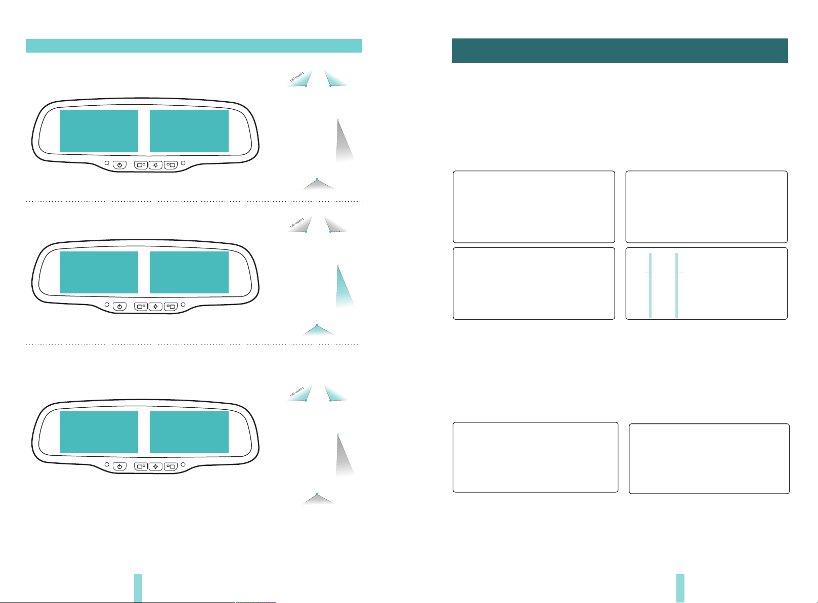
4.2 Auto dimming how to working
The auto-dimming of our mirror works automatically when you start the engine,
and the indicator will light up. The light sensor in the back of the rear view
mirror will always detect the ambient light. The auto-dimming doesn't work in
the broad day for the adequate daylight. However, when night falls and the
ambient light is weak, the auto-dimming starts to work and automatically dims
to eliminate the glare of rearward-approaching vehicles. Furthermore, the
degree of brightness of the auto-dimming glass depends on the level of the light.
The stronger the light from the back of the car is, the darker the glass is. Hence it
protects drivers from becoming dizzy and avoiding car accident.
Auto-dimming bleaching state
the light sensor from the back of
mirror detects the ambient light front light sensor detects the light
from rearward-approaching vehicles.
Auto-dimming working state
4.1 Why need dimming function
● To protect drivers from night glare of headlight.
● It is a function that can improve the car safety level.
● It may cause a series of legal disputes once removed by car dealers or sellers
Chapter Four: Auto Dimming (option)
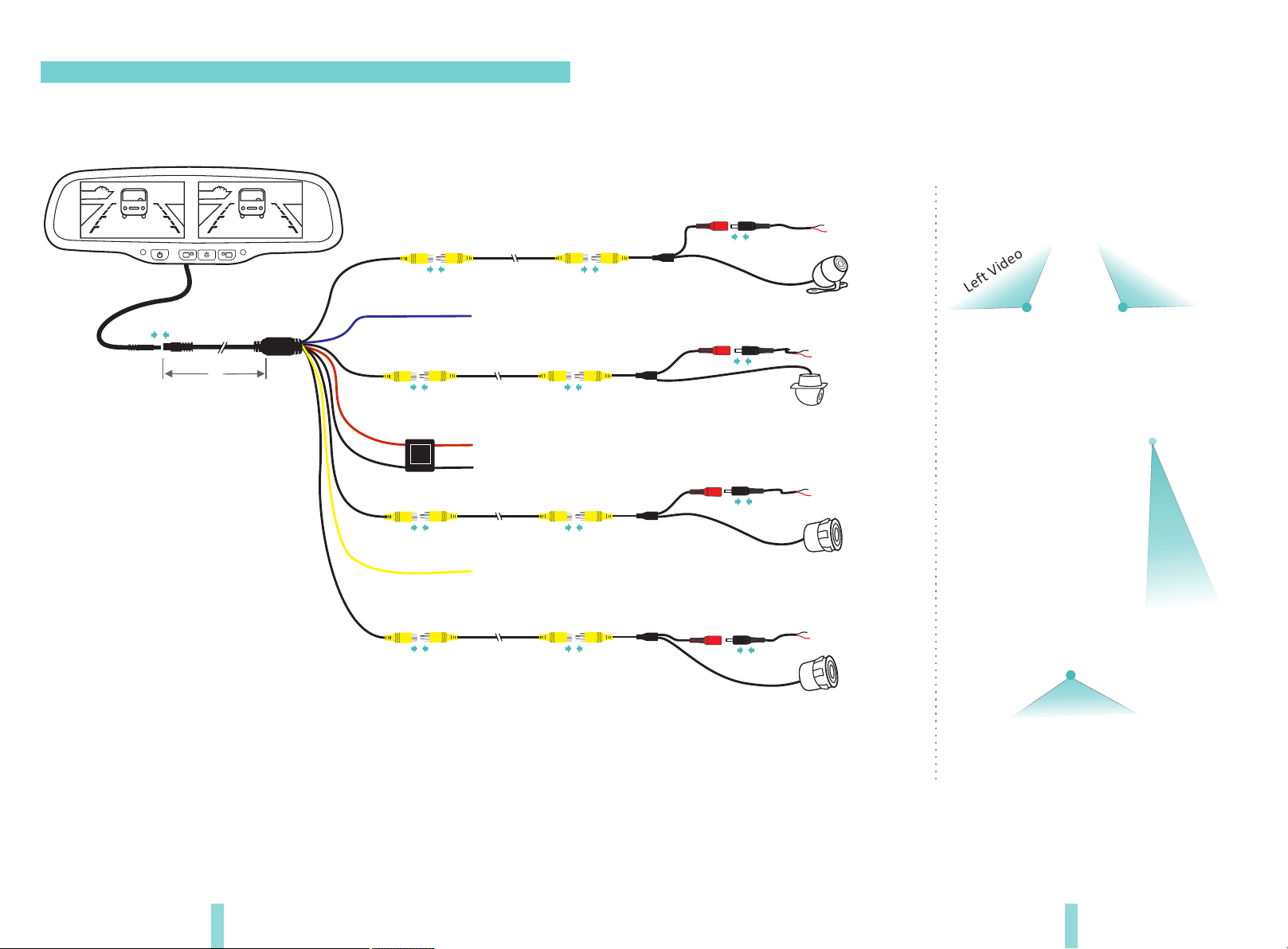
According to the site of standard reference line, we can put reference objects such
as desks in the back area of car. Compared with the marked reference objects, we
can adjust the sites and angle of two guide lines displayed on the monitor. You will
get the accurate and safety guide lines once they coincide with the reference
objects.
Press setting button is to enter into “guide line adjustment” mode. The system is
defaulted to adjust left guide line firstly. Press the button again will switch to adjust
the right guide line. The up , down left and right buttons are to
adjust the correspondent location of guide lines. The clockwise rotation and
contra rotation buttons are to adjust the angle of guide lines. It is easy to
operate and calibrate. After finishing calibration, switch the reverse gear to save
the information.
Caution: keep the remote control 0.5m-1.0m from rearview mirror when you use the remote to
adjust the parking lines.
3.2 How to adjust the guide line
Displayonthemonitor
Table of contents
Other Germid Automobile Accessories manuals
Popular Automobile Accessories manuals by other brands

Menabo
Menabo YELO 4 NS Fitting instructions

AFX MOTORSPORTS
AFX MOTORSPORTS CAN AM X3 installation manual

Whispbar
Whispbar K704W Fitting instructions

CrimeStopper
CrimeStopper CS-9601PI Wiring diagram

Metra Electronics
Metra Electronics 99-5026 installation instructions

Fiamma
Fiamma VENT 28 Installation and usage instructions