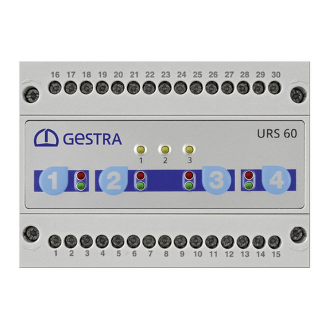
GESTRA URS 60 Installation instructions

Installation & Operating Manual
EN
English
Safety Control Unit
URS 60
URS 61
819634-01

2URS 60, URS 61 - Installation & Operating Manual - 819634-01
Contents
Content of this Manual....................................................................................................................................4
Scope of delivery/Product package................................................................................................................4
How to use this Manual...................................................................................................................................5
Illustrations and symbols used.......................................................................................................................5
Hazard symbols in this Manual.......................................................................................................................5
Types of warning .............................................................................................................................................6
Specialist terms/Abbreviations.......................................................................................................................7
Usage for the intended purpose...................................................................................................................... 8
Admissible accessories, dependent on the required safety integrity level ....................................................9
Improper use .................................................................................................................................................10
Basic safety notes .........................................................................................................................................10
Required personnel qualifications................................................................................................................10
Notes on product liability..............................................................................................................................10
Functional safety, safety integrity level (SIL) ............................................................................................... 11
Performing an annual function test ...........................................................................................................11
Reliability data to EN 61508 ..........................................................................................................................12
Function .........................................................................................................................................................13
Possible combinations of functions and equipment ...................................................................................14
Technical data ...............................................................................................................................................16
Example rating plate/identification of URS 60/URS 61 ................................................................................18
Factory settings.............................................................................................................................................19
Safety control unit URS 60 ........................................................................................................................ 19
Safety control unit URS 61 ........................................................................................................................ 19
Functional elements and dimensions...........................................................................................................20
Installing the URS 60/URS 61 safety control unit.........................................................................................21
Wiring diagram of the URS 60/URS 61 safety control unit...........................................................................22
Electrical connection.....................................................................................................................................23
Bus line, cable length and cross-section ...................................................................................................23
Connecting the 24V DC power supply .......................................................................................................23
Connecting the 24V DC I/O interface .........................................................................................................23
Instructions for connecting the safety circuit............................................................................................. 23
Notes on connecting inductive loads......................................................................................................... 23
Wiring diagram of CAN bus system..............................................................................................................24
Example ...................................................................................................................................................24
Important notes on connecting the CAN bus system..................................................................................24
3URS 60, URS 61 - Installation & Operating Manual - 819634-01
Contents
Changing the equipment settings.................................................................................................................25
Changing the baud rate ............................................................................................................................25
Configuring the limiter function.................................................................................................................26
Configuring the delay time and baud rate.................................................................................................. 27
Bringing into service – starting, operation, alarm and testing.................................................................... 28
Checking installation and function ............................................................................................................29
System malfunctions.....................................................................................................................................30
Causes .....................................................................................................................................................30
Check the installation and configuration before systematic troubleshooting: .............................................30
Indication of system malfunctions.............................................................................................................31
What to do in the event of system malfunctions?........................................................................................33
Checking installation and function ............................................................................................................33
Emergency mode...........................................................................................................................................33
Emergency mode for water level limiter systems ...................................................................................... 33
Taking out of service.....................................................................................................................................34
Disposal .........................................................................................................................................................34
Returning decontaminated equipment.........................................................................................................34
Declaration of Conformity; Standards and Directives..................................................................................35

4URS 60, URS 61 - Installation & Operating Manual - 819634-01
Content of this Manual
Product:
■ Safety Control Unit URS 60
■ Safety Control Unit URS 61
First edition:
BAN 819634-00/08-2019cm
© Copyright
All rights reserved. Any misuse, particularly reproduction and dissemination to third parties, is not permit-
ted. The General Terms & Conditions of GESTRA AG apply.
Scope of delivery/Product package
■ 1 x Safety Control Unit URS 60 or URS 61
■ 1 x Installation & Operating Manual

5URS 60, URS 61 - Installation & Operating Manual - 819634-01
How to use this Manual
This Installation & Operating Manual describes the correct use of URS 60 and URS 61 safety control units.
It applies to all persons who integrate this equipment into control systems, install, bring into service, op-
erate, maintain and dispose of this equipment. Anyone carrying out the above-mentioned activities must
have read this Installation & Operating Manual and understood its contents.
■ Read this Manual in full and follow all instructions given.
■ Please also read the instructions for use of any accessories.
■ The Installation & Operating Manual is part of the product package. Keep it in an easily accessible
location.
Availability of this Installation & Operating Manual
■ Make sure this Installation & Operating Manual is always available to the operator.
■ If you pass on or sell the equipment to a third party, please also hand over the Installation & Operating
Manual.
Hazard symbols in this Manual
Danger zone/Dangerous situation
Danger of death from electric shock
Illustrations and symbols used
1. Action to be taken
2.
■ Lists
◆ Bullet points in lists
A Keys to illustrations
Additional
information
Read the relevant
Installation & Operating Manual

6URS 60, URS 61 - Installation & Operating Manual - 819634-01
Types of warning
DANGER
Warning of a dangerous situation that will result in death or serious injury.
WARNING
Warning of a dangerous situation that may possibly result in death or serious injury.
CAUTIONCAUTION
Warning of a situation that may result in minor or moderate injury.
ATTENTIONATTENTION
Warning of a situation that will result in damage to property or the environment.

7URS 60, URS 61 - Installation & Operating Manual - 819634-01
Specialist terms/Abbreviations
Here, we explain some abbreviations, specialist terms, etc., which are used in this Manual.
IEC 61508
International standard IEC 61508 describes both the type of risk assessment and actions taken to provide
appropriate safety functions.
SIL (safety integrity level)
Safety integrity levels SIL 1 to 4 are used to quantify risk reduction. SIL 4 is the highest level of risk reduc-
tion. International standard IEC 61508 forms the basis for establishing, testing and operating technical
safety systems.
CAN (Controller Area Network) bus
Data transmission standard and interface for connecting electronic equipment, sensors and
control systems. Data can be sent and received.
TRV .. / NRG .. / LRG ... / SRL ...
Equipment and type designations of GESTRA AG, see page 9.
PhotoMOS output
PhotoMOS are a special kind of semiconductor relay, which use a light-emitting diode on the input side
that is optically coupled to an output transistor. This type of electrically non-conductive connection makes
sure the input and output circuits are electrically isolated from each other.
SELV
Safety Extra Low Voltage

8URS 60, URS 61 - Installation & Operating Manual - 819634-01
Usage for the intended purpose
URS 60 and URS 61 safety control units can be used in combination with various safety sensors of types
NRG 1..., NRG 2…, LRG 1… and TRV 5… to act as safety limiters for steam boiler and water boiler
systems.
The equipment can be used as:
■ A low-level limiter, in combination with the NRG 1x-60/NRG 26-61 level electrode.
Low-level limiters switch off the heating when the water drops below the set minimum level.
■ A safety high-level limiter, in combination with the NRG 1x-61/NRG 26-61 level electrode.
Safety high-level limiters switch off the feedwater supply when the water rises above the set maxi-
mum level.
■ A conductivity limiter, in combination with the LRG 1x-6x conductivity electrode.
Conductivity limiters switch off the heating if the set maximum conductivity is exceeded.
■ A safety temperature monitor/limiter, in combination with the TRV 5-60 temperature transmitter.
Safety temperature limiters or monitors switch off the heating when the maximum admissible temper-
ature is reached. Mode of operation TYPE 2.BKP (+JV, with external lock) to EN 60730-1.
■ The above functions may be combined.
■ The SRL 6-60 monitoring unit is available for ensuring a regular, separate flushing process when
level electrodes are used in external level pots.
■ Viewing and operation take place via a choice of operating terminals: the URB60 and SPECTOR
control
.
Usage for the intended purpose
Technical rules for steam boilers - a knowledge base:
This Manual occasionally refers to EN 12952 as a knowledge base.
These regulations have not been in force since 01/03/2019 and are no longer updated.
They have been replaced by the TRBS (German Technical Rules for Operational Safety).
Always observe the current regulations (EU directives, EN standards, information from emplo-
yers’ liability insurance associations, etc.) in order to comply with the current state of the art.

9URS 60, URS 61 - Installation & Operating Manual - 819634-01
Usage for the intended purpose
Admissible accessories, dependent on the required safety integrity level
URS 60 and URS 61 safety control units can be operated with the following system components:
Low-level
limiter
Safety
high-level
limiter
Conductivity
limiter
Temperature
limiter
Operating
unit
Monitoring
unit
SIL 3
to
EN 61508
NRG 16-60
NRG 17-60
NRG 19-60
NRG 111-60
NRG 16-61
NRG 17-61
NRG 19-61
NRG 111-61
– TRV 5-60
URB 60
SPECTOR
control
SRL 6-60
SIL 2
to
EN 61508
NRG 26-61
NRG 16-60
NRG 17-60
NRG 19-60
NRG 111-60
NRG 26-61
NRG 16-61
NRG 17-61
NRG 19-61
NRG 111-61
LRG 16-60
LRG 16-61
LRG 17-60
TRV 5-60
URB 60
SPECTOR
control
SRL 6-60
Fig. 1
Key to Fig. 1:
NRG = level electrode
LRG = conductivity electrode
TRV = temperature transmitter
URB = visual display and operating unit
SRL = monitoring unit
To ensure the proper use of equipment during all types of use, please also read the Installation
& Operating Manuals for the sensors and operating units used.
■ You will find the current Installation & Operating Manuals for the safety sensors and operat-
ing units named in Fig. 1 on our website: http://www.gestra.com

10 URS 60, URS 61 - Installation & Operating Manual - 819634-01
Improper use
There is a danger of death due to explosion if the equipment is used in potentially explo-
sive atmospheres.
Do not use the equipment in potentially explosive atmospheres.
Basic safety notes
There is a risk of electric shock during work on electrical systems.
■ Always switch off the voltage to the equipment before performing work on the terminal
strips.
■ Check that the plant is not carrying live voltage before commencing work.
Attempts to repair the equipment will cause the plant to become unsafe.
■ Do not repair the URS 60/URS 61 safety control unit.
■ Only replace faulty equipment with identical equipment from GESTRA AG.
Required personnel qualifications
Activity Personnel
Integration in control system Specialist staff Plant designer
Installation/electrical
connection/bringing into service Specialist staff Electrician/installer
Operation Boiler service technician Staff trained by the plant
operator
Maintenance work Specialist staff Electrician
Refits Specialist staff Plant construction
Fig. 2
Notes on product liability
We the manufacturer cannot accept any liability for damages resulting from improper use of the equip-
ment.

11URS 60, URS 61 - Installation & Operating Manual - 819634-01
Functional safety, safety integrity level (SIL)
The URS 60/URS 61 safety control unit is suitable for safety functions up to SIL 3.
It is an element of a safety circuit up to SIL 3 as per EN 61508 in the SPECTOR
connect
system, and can
process alarm indications from up to four safety sensors.
When combined with the accessories, you will have a type B subsystem. The technical and safety charac-
teristics in Fig. 4 are based on the URS 60/URS 61 safety control unit with output contacts.
Breakdown of safety function failure rates
Sensor
probe
The CANopen interface is a “black channel” type, and can be ignored during calculation due to
the low failure rate of < 1FIT.
CANopen URS 60,
URS 61
Burner
safety circuit
Sensor
electronics
Fig. 3
Performing an annual function test
Check the function of the URS 60/URS 61 safety control unit at least once a year by triggering the safety
circuit (T1 = 1 year). You can check the function either by pressing buttons 1 – 4 (see page 28) or by
making the equipment actually exceed the limit values.
Sensor

12 URS 60, URS 61 - Installation & Operating Manual - 819634-01
Reliability data to EN 61508
Description Characteristic values
Safety integrity level SIL 3
Architecture 1oo1
Type of equipment Type B
Hardware fault tolerance HFT = 0
Overall failure rate for dangerous undetected failures λDU < 20.0 * 10-9 1/h
Overall failure rate for dangerous detected failures λDD < 2000 * 10-9 1/h
Safe failure fraction SFF > 99.0%
Test interval T1 = 1 year
Probability of dangerous failure on demand PFD < 20.0 * 10-5
Diagnostic coverage. Percentage of dangerous failures
detected by a test. DC > 99.0%
Mean time to dangerous failure MTTFD> 90 a
Diagnostic interval T2 = 1 hour
Performance level (to ISO 13849) PL = d
Probability of dangerous failure on demand
per hour PFH < 20 * 10-9 1/h
Ambient temperature as a basis for calculation Tu = 45 °C
Mean time to repair MTTR = 0 (no repair)
Fraction of undetected dangerous failures that have a
common cause beta = 2%
Fraction of detected dangerous failures that have a com-
mon cause beta d = 1%
Fig. 4

13URS 60, URS 61 - Installation & Operating Manual - 819634-01
Function
The URS 60/URS 61 safety control unit cyclically evaluates data telegrams from up to four safety sensors
of types NRG 1..., NRG 2…, LRG 1… and TRV 5. The data are transferred via ISO 11898 CAN bus using
the CANopen protocol, and saved. The safety functions are monitored by cyclical self-tests. The two
integrated relays are switched off in the event of alarms or errors. Function tests and failure diagnosis can
be performed using the control unit or an operating terminal.
The data telegrams contain the following information:
■ Sensor alarms if the limits are exceeded
■ Fault indications on the occurrence of faults in electronic or mechanical parts
■ Excessive temperature in the sensor terminal boxes
Behaviour in the event of alarms
When level, temperature or conductivity alarms occur, both output contacts open after a power-off delay
and this interrupts the safety circuit (fail-safe position). The safety control unit does not lock independent-
ly; this function must be implemented in the downstream circuit. The URS 60 or URS 61 can only activate
one safety circuit (heater or pump) at any one time.
The safety circuit is interrupted without a delay if the following fault indications occur:
■ Fault in sensors (negative self-test, excessively high temperature in terminal box)
■ Fault in control unit (negative self-test)
■ Communication failure
Behaviour in the event of fault indications
Cyclical self-tests monitor the safety functions of the equipment in the safety control unit and sensors.
Fault indications are updated with each self-test. If there are no faults, the message is automatically
deleted and the output contacts close once more. Alarms and fault indications are displayed by LEDs or an
operating unit.
In addition, you can choose to have alarms displayed on an external signalling device via the signalling
outputs, either with or without a delay. Faults are always indicated without a delay, however.
Alarm simulation
You can simulate alarms by pressing the button or via external 24V DC signals.
Monitoring flushing processes
If a level electrode is installed outside the boiler in a level pot that can be shut off, the connecting pipes
must be flushed regularly. During a flushing process, the water level is not measured in
the level pot for up to five minutes. When prompted by an SRL 6-60 monitoring unit, the URS 60/URS 61
safety control unit therefore bypasses the level electrode and monitors the maximum bypass time.
If the steam pipe is ≥ 40 mm and the water pipe is ≥ 100 mm, installation is regarded as internal. In this
case, upstream monitoring of flushing processes is not required.

14 URS 60, URS 61 - Installation & Operating Manual - 819634-01
Function
Possible combinations of functions and equipment
Combining sensors and safety control units in a circuit produces the following common combinations of
functions:
Abbreviations used in Fig. 5 and Fig. 6
SLLL = safety low-level limiter
STL = safety temperature limiter
SHLL = safety high-level limiter
SCL = safety conductivity limiter
URS 60
e.g. safety circuit for heating
Function 1 Function 2 Function 3 Function 4
SLLL 1 with
level electrode
NRG 1x-60
SLLL 1 with
level electrode
NRG 1x-60
SLLL 2 with
level electrode
NRG 1x-60
NRG 26-61
SLLL 1 with
level electrode
NRG 1x-60
SLLL 2 with
level electrode
NRG 1x-60
NRG 26-61
STL (STM) 1 with
temperature transmitter
TRV 5-60
SCL 1 with
conductivity electrode
LRG 1x-6x
SLLL 1 with
level electrode
NRG 1x-60
SLLL 2 with
level electrode
NRG 1x-60
NRG 26-61
STL (STM) 1 with
temperature transmitter
TRV 5-60
SLLL 1 with
level electrode
NRG 1x-60
SLLL 2 with
level electrode
NRG 1x-60
NRG 26-61
SHLL 1 with
level electrode
NRG 1x-61
NRG 26-61
STL (STM) 1 with
temperature transmitter
TRV 5-60
SLLL 1 with
level electrode
NRG 1x-60
SLLL 2 with
level electrode
NRG 1x-60
NRG 26-61
STL (STM) 1 with
temperature transmitter
TRV 5-60
STL (STM) 2 with
temperature transmitter
TRV 5-60
STL (STM) 1 with
temperature transmitter
TRV 5-60
STL (STM) 2 with
temperature transmitter
TRV 5-60
STL (STM) 1 with
temperature transmitter
TRV 5-60
STL (STM) 2 with
temperature transmitter
TRV 5-60
STL (STM) 3 with
temperature transmitter
TRV 5-60
STL (STM) 4 with
temperature transmitter
TRV 5-60
Fig. 5

15URS 60, URS 61 - Installation & Operating Manual - 819634-01
Function
URS 61
e.g. safety circuit for feedwater pump
Function 1 Function 2 Function 3 Function 4
SHLL 1 with
level electrode
NRG 1x-61
NRG 26-61
SHLL 1 with
level electrode
NRG 1x-61
NRG 26-61
STL (STM) 1 with
temperature transmitter
TRV 5-60
SHLL 1 with
level electrode
NRG 1x-61
NRG 26-61
SHLL 1 with
level electrode
NRG 1x-61
NRG 26-61
STL (STM) 2 with
temperature transmitter
TRV 5-60
STL (STM) 3 with
temperature transmitter
TRV 5-60
SCL 1 with
conductivity electrode
LRG 1x-6x
STL (STM) 3 with
temperature transmitter
TRV 5-60
STL (STM) 3 with
temperature transmitter
TRV 5-60
STL (STM) 4 with
temperature transmitter
TRV 5-60
STL (STM) 5 with
temperature transmitter
TRV 5-60
STL (STM) 6 with
temperature transmitter
TRV 5-60
STL (STM) 7 with
temperature transmitter
TRV 5-60
STL (STM) 8 with
temperature transmitter
TRV 5-60
Fig. 6
Further combinations are possible and permitted.
The limiter ID defines the channel on the relevant safety control unit
ID = 1 > URS 60, channel 1 ID = 5 > URS 61, channel 1
ID = 2 > URS 60, channel 2 ID = 6 > URS 61, channel 2
ID = 3 > URS 60, channel 3 ID = 7 > URS 61, channel 3
ID = 4 > URS 60, channel 4 ID = 8 > URS 61, channel 4
■ Only one URS 60 and one URS 61 control unit may be used in the CAN bus network.

16 URS 60, URS 61 - Installation & Operating Manual - 819634-01
Technical data
Supply voltage
■ 24V DC +/-20%
Power consumption
■ Max. 7 W
Current input
■ Max. 0.3 A
Internal fuse
■ T2A
Input/output
■ Interface for CAN bus to ISO 11898, CANopen, insulated
Safety circuit output
■ 2 volt-free relay contacts, connected externally in series. Contact material AgNi
■ Maximum switching current at switching voltages of 24 V AC/DC, 115 V AC and 230 V AC: ohmic/
inductive 6 A
■ Connected contactors must have interference suppression (RC combination) as per the manufactur-
er's specifications
Required external fuse for the safety circuit
■ T2A or T1A for (EN 12952 *), 72 hrs. of operation
* see page 8
Signal output
■ 4 PhotoMOS outputs for external signalling, either with or without a delay
■ 24 DC, max. current load 100 mA, NO characteristic
Test input
■ 4 opto-coupler inputs for external test triggering, high active, 24V DC +/- 20%
Output relay OFF delay
■ Factory default setting 3 seconds.
■ Option of 10 seconds or 15 seconds
Indicators and controls
■ 4 x buttons for operation/initiating test function in sensor
■ 4 x green LEDs for indicating active channels
■ 4 x red LEDs for indicating a malfunction/alarm
■ 3 x yellow LEDs for indicating internal errors and external sensor errors
■ 1 x 10-pole code switch for setting the number of limiters, the delay and baud rate

17URS 60, URS 61 - Installation & Operating Manual - 819634-01
Technical data
Protection class
■ II double insulated
IP rating to EN 60529
■ Terminal box: IP 40
■ Terminal strip: IP 20
Admissible ambient conditions
■ Service temperature: 0 °C – 55 °C - installed in control cabinet
■ Storage temperature: - 40 °C – 80 °C
■ Transport temperature: - 40 °C – 80 °C
■ Air humidity: 10% – 95%, non-condensing
■ Altitude: up to 2000 m
Terminal box
■ Terminal box material: Lower section of black polycarbonate (glass-fibre reinforced), front of grey
polycarbonate
■ 2 x 15-pole terminal strips, removable separately
■ Max. cross-section per screw terminal:
◆ 1 x 4.0 mm2solid, or
◆ 1 x 2.5 mm2stranded with sleeve, or
◆ 2 x 1.5 mm2stranded with sleeve
■ Terminal box attachment: Mounting clip on support rail TH 35 (to EN 60715)
■ Installation in control cabinet (IP54) required
Weight
■ Approx. 0.4 kg

18 URS 60, URS 61 - Installation & Operating Manual - 819634-01
Fig. 7
Example rating plate/identification of URS 60/URS 61
The date of production is printed on the side of the equipment.
$
$
1/=><++1
7ÞXMROXO\=^\!!
",\OWOX
7KNOSX1O\WKXc
1Safety note
2Equipment function
3Equipment designation
4Power consumption
5IP rating
6Operating data
(maximum ambient temperature)
7Power supply
8Protection class
9Wiring diagram
0Component type approval
aMaterial number-serial number
bManufacturer
cComponent type approval
dDisposal information
Optional information
eMeasuring range in µS/cm
fMeasuring range in ppm
gCutout relay
hInformation on functional safety
iMarking for temperature limiters (STL)
or monitors (STM)
jField for set limit value
kMode of operation in accordance with EN
60730-1

19URS 60, URS 61 - Installation & Operating Manual - 819634-01
Factory settings
Safety control unit URS 60
■ Baud rate: 50 kbit/s (max. cable length 1000 m)
■ Signalling delay: OFF
■ Configuration:
Operation e.g. with two NRG 1x-60 level electrodes
■ Code switch setting - sliding switch, white
1
ON
2345678910
1
ON
2345678910
Safety control unit URS 61
■ Baud rate: 50 kbit/s (max. cable length 1000 m)
■ Signalling delay: OFF
■ Configuration:
Operation e.g. with one NRG 1x-61 level electrode
■ Code switch setting - sliding switch, white

20 URS 60, URS 61 - Installation & Operating Manual - 819634-01
A Upper terminal strip
B Lower terminal strip
C Screws (M3)
D 10-pole code switch, for setting the number of
limiters, the delay and baud rate
E Front membrane with operating keys and LEDs,
see page 28
F Terminal box
G Support rail TH 35
Functional elements and dimensions
12345678910 11 12 13 14 15
100
73
118
1
2
MAX
1
2716 17 18 19 20 21 22 23 24 25 26 28 29 30
A
B C
F
G
D
E
The code switch can be accessed by
disconnecting and removing the lower
terminal strip.
Equipment settings,
see page 26.
Fig. 8
12345678910 11 12 13 14 15
100
73
118
1
2
MAX
1
2716 17 18 19 20 21 22 23 24 25 26 28 29 30
Other manuals for URS 60
1
This manual suits for next models
1
Table of contents
Other GESTRA Control Unit manuals

GESTRA
GESTRA ZK 29 User manual

GESTRA
GESTRA NRS 1-40.1 User manual

GESTRA
GESTRA LRR 1-40 User manual

GESTRA
GESTRA ZK 313 User manual

GESTRA
GESTRA URS 60 User manual

GESTRA
GESTRA NRR 2-2e Quick guide

GESTRA
GESTRA CW 44 User manual

GESTRA
GESTRA SRL 6-50 User manual

GESTRA
GESTRA ZK 213 User manual

GESTRA
GESTRA BK 15 User manual

GESTRA
GESTRA GK 11 User manual

GESTRA
GESTRA Gestramat CW 41 User manual

GESTRA
GESTRA CB 26 User manual

GESTRA
GESTRA QuickEM User manual

GESTRA
GESTRA BB 1 Series User manual

GESTRA
GESTRA UNA 43 User manual

GESTRA
GESTRA AK 45 User manual

GESTRA
GESTRA BA 46 User manual

GESTRA
GESTRA TRS 5-40 User manual

GESTRA
GESTRA BW 31A User manual