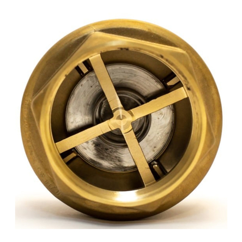
GESTRA BB 1 Series User manual

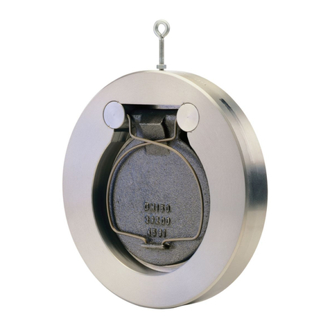
Double Swing Check Valve
BB 1
BB 2
BB 3
Original Installation Instructions
819649-00

Contents
Foreword ............................................................................................................................................3
Availability.............................................................................................................................................3
Formatting features in the document ......................................................................................................3
Safety..................................................................................................................................................3
Use for the intended purpose .................................................................................................................3
Basic safety notes .................................................................................................................................4
Typographic features of warning notes....................................................................................................5
Formatting features for warnings of property damage ..............................................................................5
Description .........................................................................................................................................5
Scope of supply and equipment specification ..........................................................................................5
Application of European Directives........................................................................................................10
Task and function................................................................................................................................10
End connections..................................................................................................................................11
Storing and transporting the equipment.........................................................................................11
Storing the equipment .........................................................................................................................11
Transporting the equipment .................................................................................................................11
Mounting and connecting the equipment .......................................................................................12
Preparing installation ...........................................................................................................................12
Mounting the equipment ......................................................................................................................12
Operation ..........................................................................................................................................16
After operation .................................................................................................................................16
Removing external dirt deposits............................................................................................................16
Maintaining the equipment...................................................................................................................16
Servicing the equipment and installing spare parts ................................................................................17
Troubleshooting ...............................................................................................................................28
Putting the equipment out of operation ..........................................................................................29
Removing harmful substances..............................................................................................................29
Removing the equipment .....................................................................................................................29
Re-using equipment after storage.........................................................................................................30
Disposing of the equipment..................................................................................................................30
Technical data..................................................................................................................................33
Dimensions and weights ......................................................................................................................33
Pressure & temperature ratings............................................................................................................45
Manufacturer's declaration .............................................................................................................49

3
Foreword
This installation & operating manual will help you
use the following types of equipment safely and
efficiently for their intended purpose.
Double swing check valve BB 1
Double swing check valve BB 2
Double swing check valve BB 3
These types will be called equipment in this
document.
This installation & operating manual is intended for
anyone commissioning, using, operating, servicing,
cleaning or disposing of this equipment and, in
particular, for professional after-sales service
technicians, qualified personnel and authorised and
trained staff.
All of these persons must read and understand the
content of this installation & operating manual.
Following the instructions given in this installation &
operating manual helps avoiding danger and
increases the reliability and service life of the
equipment. Please note that in addition to the
instructions given in this installation & operating
manual you must also observe all locally applicable
rules and regulations concerning the prevention of
accidents as well as approved safety guidelines for
good professional practice.
Availability
Keep this installation & operating manual together
with the plant documentation for future reference.
Make sure that this installation & operating manual
is available to the operator.
The installation & operating manual is part of the
equipment. Please hand over this installation &
operating manual when selling the equipment or
passing it on.
Formatting features in the
document
Certain text elements of this installation & operating
manual feature a specific typographic design. You
can easily distinguish the following text elements:
Standard text
Cross-reference
Listing
Sub-items in listings
Steps for action.
Here you will find additional useful
information and tips serving to assist you
in using the equipment to its fullest
potential.
Safety
Use for the intended purpose
Swing check valves ensure unidirectional flow in
pipes by preventing a backflow of liquids or gases.
The equipment must only be used within the
allowable pressure and temperature limits and only
if the chemical and corrosive influences on the
equipment are taken into account.
Correct use includes compliance with the
instructions given in this installation & operating
manual, in particular obedience to all safety
instructions.
Any other use of the equipment is considered to be
improper.
The equipment is also considered to be used
improperly if:
the equipment is installed in pipes where the
fluid is delivered by a piston pump or
compressor
a damper is used outside the rated
pressure/temperature range
the equipment is used as end valve in a steam
line
The equipment is also used improperly if the
materials of the equipment are not suitable for the
intended service conditions.

4
Basic safety notes
Risk of severe injuries
The equipment is under pressure during
operation and may be hot. Before carrying out
any work on the equipment make sure that the
following requirements are met:
The pipes must be depressurized (0 bar).
The fluid must be completely removed from
the pipes and the equipment.
During work on the equipment the
installation must be switched off and
protected against unauthorised or
unintended activation.
The pipes and the equipment must have
cooled down to room temperature (approx.
20 °C).
If the equipment is used in contaminated areas
there is a risk of severe injuries or death caused
by harmful substances in or on the equipment.
Before working on the equipment make sure
that it is completely decontaminated. Always
wear the protective clothing prescribed for
contaminated areas when working on the
equipment.
The equipment must only be used with fluids
that do not attack the material and the gaskets
and sealings of the equipment. Otherwise leaks
may occur and hot or toxic fluid could escape.
The equipment and its component parts must
only be mounted or removed by qualified
personnel. A qualified person must be
acquainted with and experienced in the
following:
Making pipe connections.
Selecting suitable lifting gear and
understanding the rules for its safe use.
Working with dangerous (contaminated, hot
or pressurized) fluids.
If installation or removal work is carried out
carelessly the springs may shoot out of the body
and injure personnel.
Always wear safety goggles when mounting or
removing the springs.
When working on the springs make sure that no
uninvolved persons are standing in close vicinity
of the equipment.
If the admissible temperature and pressure
limits are exceeded the equipment may be
destroyed and hot or pressurized fluid may
escape. Make sure that the equipment is only
operated within the admissible service range
and limits.
For more information on limits and pressure &
temperature ratings see name plate and the
section "
Technical Data
".
Risk of minor injuries
Sharp edges on internals present the danger of
cuts to hands. Always wear industrial gloves
when servicing the equipment.
If the support of the equipment during
installation is insufficient the equipment might
fall down, thereby causing bruises or injuries.
Make sure the equipment is safely held in place
during installation and cannot fall down. Wear
protective safety footwear.
Information on property damage or
malfunctions
Malfunctions will occur if the equipment is
installed in a wrong position or with the flow
pattern in the opposite direction of the fluid flow.
This may result in damage to the equipment or
the installation. Make sure that the flow pattern
indicated on the name plate matches the
direction of the fluid flow in the pipe.
If the material is unsuitable for the fluid,
increased wear may occur and fluid may
escape. Make sure that the material is suitable
for the fluid used in your installation.
The equipment may get damaged by pressure
impulses, even if the admissible nominal
pressure PN is not exceeded.
Make sure that the equipment is not subject to
pressure impulses or heavily pulsating flow.
If the dampers are subjected to stress the
equipment may get damaged. Do not use the
dampers to lift the equipment. Do not step on
the dampers.
If the dampers are adjusted incorrectly,
malfunctions may occur or the equipment may
get damaged. Do not change the factory
settings of the dampers.
5
Typographic features of warning
notes
DANGER
Notes with the heading DANGER warn
against imminent dangerous situations that
can lead to death or serious injuries.
WARNING
Notes with the
heading WARNING warn
against possibly dangerous situations that
could lead to death or serious injuries.
CAUTION
Notes with the heading CAUTION warn
against dangerous situations that could
lead to minor or moderate injuries.
Formatting features for warnings
of property damage
Attention!
This information warns of a situation
leading to property damage.
Description
Scope of supply and equipment
specification
Scope of supply
Our equipment is delivered packed and ready for
assembly.
Equipment series and optional extras
Equipment types BB 1 and BB 2 differ from each
other in the way the hinge pins for the discs in the
body are attached.
Various types of equipment are available which
differ from each other in the following:
Pressure rating
Body material
Nominal size
Seat
Type of spring
Designed and manufactured in accordance with
DIN or ASME
Installation of an optional damper (only with
equipment with specially designed body).
The valves are available with the following pressure
ratings:
Type
PN
CLASS
(ASME)
BB 11, BB 21
6
–
BB 12, BB 22, BB 32
10
BB 14, BB 24, BB 34
16
–
BB 35
25
150
BB 36
40
300
BB 17
63
–
BB 18
100
600
BB 19
160
900
The body may be made of the following materials:
Code
Material
G
Grey cast iron
GS
Grey cast iron with hard
rubber coating
GK Grey cast iron with
plastic coating
C
Steel
A
Stainless steel

6
The equipment can feature a seat made from:
Metal-to-metal
EPDM
FPM (FKM)
NBR
PTFE
The following springs are available.
Code number/letter
Application
7 WA
Spring for 7 mbar
opening pressure, for
horizontal installation
7 WAI
Inconel spring for 7 mbar
opening pressure, for
horizontal install
ation and
temperatures > 300 °C
2 WA Spring for 2 mbar
opening pressure, for
horizontal installation
5 VO
Spring for 5 mbar
opening pressure, for
vertical installation with
downward flow
For more information on the opening pressures of
the spring see the data sheet.
The type designation is a sequence of
alphanumerical characters that specifies the type of
equipment. If the letters "DPF" are indicated in the
type designation, it denotes the installation of a
damper.
Examples of type designations
"BB 32 A 350 EPDM 5 VO"
BB, PN 10, stainless steel body, nominal size
350, EPDM seat gasket and 5 mbar springs for
direction of flow from above.
"BB 36 C 150 FPM 7 WA"
BB, PN 40, steel body, nominal size 150, FPM
seat gasket and 7 mbar springs for horizontal
direction of flow.

7
Equipment specification
Units BB 1 and BB 3 DN 50–125, DN 450–500
In these units, the bearing pins of the swing discs
are mounted on bearings in the body.
No.
Designation
1
Seal screw with gasket1
2 Eye bolt
3 Name plate with flow direction arrow
4
Body
5
Angle bracket or fixing plate for plates
2
No.
Designation
6
Seal3
7 2 pairs of springs
8 Plates
9
Hinge pins
1
2 seal screws on top and 2 on bottom of the body. Smaller equipment features only 2 seal screws on
top of the body.
2 Depending on the type of equipment angle brackets or fixing plates are used. The following drawings
show equipment with angle brackets.
3
Some types of equipment have metal-to-metal seats.

8
Units BB 2 and BB 3, DN 150–400
In these units, the bearing pins of the swing discs
are mounted on bearing blocks in the body.
No.
Designation
2 Eye bolt
3
Name plate with flow direction arrow
4
Body
6
Seal1
7
2 pairs of springs
No.
Designation
8 Plates
9
Hinge pins
10
Plate support for plates with threaded bolt
11
Threaded bolt
1
Some types of equipment have metal-to-metal seats.

9
Equipment with damper
Equipment with optional damper and a corresponding bore in the equipment is available.
No.
Designation
12
Damper with gasket
For fitting the damper the body of the
equipment must be provided with a bore.
The standard body does not have such a
bore and can therefore not be equipped
with a damper.

10
Name plate
The indications on the name plates vary according
to the equipment type.
The name plate may specify the following:
Manufacturer
Type designation
Design
Nominal size
Pressure rating
Direction of flow
CE marking
Date of manufacturing
Serial number
Maximum operating pressure at the associated
operating temperature
Minimum operating pressure at the associated
operating temperature
Material specification of plates and seat
Small equipment has the technical
specification embossed on its body.
Application of European Directives
Pressure Equipment Directive
The equipment conforms to this directive (see
"Manufacturer's Declaration" section) and can be
used for the following media:
BB G, BB GS and BB GK:
Fluids of group 2
BB A and BB C:
Fluids of group 1
Fluids of group 2
ATEX Directive
The equipment does not have its own potential
ignition source and is not subject to this directive
(see "Manufacturer's Declaration" section).
When installed, static electricity may arise between
the equipment and the connected system.
When used in potentially explosive atmospheres,
the plant manufacturer or plant operator is
responsible for discharging or preventing possible
static charge.
If it is possible for medium to escape, e.g. through
actuating mechanisms or leaks in threaded joints,
the plant manufacturer or plant operator must take
this into consideration when dividing the area into
zones.
Task and function
Purpose
The equipment prevents the backflow of liquids or
gases in pipes.
The equipment can be installed in horizontal and
vertical pipes.
If the equipment is mounted in a vertical pipe the
flow must normally be from bottom to top.
If springs of type 5 VO are used, the equipment can
also be installed in vertical pipes with downward
flow. This kind of installation (vertically downward
flow) is only possible with equipment up to
DN 500.
Function
Two valve plates open and close the pipe as a
function of the flow direction of the fluid.
Each one of the two plates is closed by two springs
guided by the hinge pin. The opening pressure
depends on the type of spring used.

11
Dampers
Optional dampers can be used to influence the
closing characteristics. A dampening medium slows
down the plate movement during the last 15° of the
closing path. As a result the plates close more
slowly and, as a consequence, problems caused by
pressure surges in the pipe are prevented.
The optional dampers can be used with
temperatures up to 110 °C.
Note that the dampers must not be used in
pressure booster installations if the pressure at the
suction side exceeds 0.5 bar.
In these installations pressure compensation
between the suction and the pressure side of the
equipment may occur. The equipment may not
close properly any longer.
End connections
The equipment can be installed between flanges as
per EN 1092-1.
Equipment types BB 1 ASME and BB 3 ASME can
be installed between flanges as per ASME B16.5 or
B16.47.
Storing and transporting the
equipment
Attention
!
Equipment can be d
amaged if stored or
transported improperly.
Close all openings with the sealing
plugs or covers supplied with the
equipment or use similar sealing
covers.
Protect the equipment against
moisture and corrosive atmospheres.
Please contact the manufacturer if
the
specified transport and/or storage
requirements cannot be met.
Storing the equipment
Please observe the following items when storing
the equipment:
Do not store the equipment for more than 12
months.
Protect the sealing surfaces and contact areas
against mechanical damage.
Protect the equipment and all components
against hard shocks and impacts.
Store the equipment only in closed rooms that
meet the following environmental conditions:
Air humidity below 50 %, not condensing
Indoor air: clean, salt-free and non-corrosive
Temperature 5–40 °C.
Make sure that all these requirements are
always met when storing the equipment.
Please contact the manufacturer if you cannot
comply with the recommended storage
conditions.
Transporting the equipment
Meet the requirements for storage also when
transporting the equipment.
For short distances (only a few metres) you can
transport the equipment unpacked.
When transporting the equipment over larger
distances use the original packaging.
If you do not have the original packaging use a
box that protects the equipment adequately
against corrosion and physical damage.
For a short period of time the equipment
may be transported even if the
temperature is below 0
°C, provided that
the equipment is completely empty and
dry.

12
Mounting and connecting the
equipment
Preparing installation
Take the equipment out of the transport
packaging.
Check the equipment for transport damage.
Contact the manufacturer if you detect any kind
of shipping damage.
DANGER
Personnel working on pipes are exposed to
safety risks and may suffer severe injuries,
poisoning or even loss of life.
Make sure that no hot or hazardous
fluid is in the equipment or the pipes.
Make sure that the pipes upstream
and downstream of the equipment are
depressurised.
Make sure that the installation is
switched off and protected against
unauthorised or unintended activation.
Make sure that the equipment
and the
pipes have cooled down to room
temperatures.
Wear protective clothing that is
suitable for the fluid and, if necessary,
wear protective gear.
For more information on suitable protective clothing
and safety gear refer to the safety data sheet of the
fluid in question.
Drain pipes until they are empty.
Switch the installation off and protect it against
unauthorised or unintended re-activation.
Mounting the equipment
Attention
!
Equipment will be damaged if the end
connections are undersized.
Make sure that the connections are
strong and rigid enough to support
the
weight of the equipment and to
withstand the forces that occur during
operation.
Attention
!
Excessive loads may damage the closing
dampers.
Use the eye bolt for fixing lifting gear.
Do not stress the closing dampers.
Make sure that the pipe system of the plant is
clean.
Make sure that the equipment is free from
foreign matter.
Ensure that all joint faces and sealing surfaces
are clean.
Make sure that the equipment is safely mounted
and that all connections are made correctly.
If the fluid temperature exceeds 300 °C a spring
made from Inconel must be fitted.
Make sure that the equipment is only operated
within the admissible service range and limits.
The equipment can be installed in horizontal or
vertical pipes. There is no significant difference in
the installation work.
The equipment can also be installed in pipes with
bends. In this case you have to install the
equipment downstream of the pipe bend.

13
A straight distanceof at least five times the nominal
pipe diameter for stabilizing the flow pattern must
be left upstream of the equipment.
Attention
!
Malfunctions may occur if the stabilizing
distance is not sufficient.
Make sure that the distance between
the pump and the equipment is
enough to provide a stabilized flow
pattern.
Installing the equipment with vertical
direction of flow
DANGER
Incorrectly connected equipment can result
in accidents with extremely severe injuries
or death.
Make sure that only specialist
personnel connect the equipment to
the pipe.
Make sure that the direction of flow in
the pipe matches the flow direction
arrow on the equipment.
Make sure that the connected pipe
does not subject the body to any
stress (forces or torques) during
installation and operation.
Specialist personnel must have knowledge and
experience of the type of pipe connection used.
Attention!
If the installation position is
incorrect
malfunctions may occur and/or the
equipment or the installation may get
damaged.
Make sure that the equipment is
installed in the correct position.
Mount the equipment downsteam of a
pipe bend.
When installing the equipment make
sure that the eye bolt points towards
the inside of the pipe bend.
The correct position of installation is indicated by
the position of the eye bolt and the flow arrow on
the nameplate.

14
If the equipment is installed in a vertical pipe the
flow arrow must point upwards.
The equipment can also be installed in
vertical pipes with downward flow.
For this purpose make sure that the
equipment is fitted with springs of type
5 VO.
If the equipment is installed downstream of a pipe
bend the eye bolt must point towards the inside of
the pipe bend.
Put a commercially available gasket that is
suitable for the pipe onto the lower flange.
Put the equipment onto the gasket.
Put a commercially available gasket that is
suitable for the pipe onto the equipment.
Put the upper flange onto it.
Insert all bolts through the holes in the flange.
Make sure that all component parts are in
central alignment with each other.
Screw the nuts onto the bolts.
To obtain the desired position of
installation you can turn the equipment
with the eye bolt.
Turn the equipment into the desired installation
position.
Tighten the nuts on the bolts evenly.
The torque required for tightening the nuts
depends on the pipe.

15
Installing the equipment with horizontal
direction of flow
DANGER
Incorrectly connected equipment can result
in accidents with extremely severe injuries
or death.
Make sure that only specialist
personnel connect the equipment to
the pipe.
Make
sure that the direction of flow in
the pipe matches the flow direction
arrow on the equipment.
Make sure that the connected pipe
does not subject the body to any
stress (forces or torques) during
installation and operation.
Specialist personnel must have knowledge and
experience of the type of pipe connection used.
A
ttention!
If the installation position is incorrect
malfunctions may occur and/or the
equipment or the installation may get
damaged.
Make sure that the equipment is
installed in the correct position.
When installing the equipment make
sure that the eye bolt points upwards.
The correct position of installation is indicated by
the position of the eye bolt and the flow arrow on
the nameplate.
If the equipment is installed in a horizontal pipe the
eye bolts must point upwards.
If the equipment is installed in horizontal
position you can use the lower bolts as
support for the equipment.
First insert the lower bolts through the holes in
the flange.
Then insert the two lower bolts into the second
flange.
Put two commercially available gaskets that are
suitable for the pipe between the flanges.
Put the equipment between the gaskets.
Make sure that all component parts are in
central alignment with each other.
Insert the upper bolts.
Align the equipment so that the eye bolt points
upwards.
Tighten the nuts on the bolts evenly.
The torque required for tightening the nuts
depends on the pipe.

16
Operation
Do not work on the equipment while it is operating.
After operation
DANGER
If fluid escapes personnel may suffer
severe injuries, poisoning or even loss of
life.
After working on the equipment make
sure that all connections and valves
are tight.
Make sure that the gaskets of the
body are leakproof.
DANGER
If the equipment is used in contaminated
areas there is a risk of severe injuries or
death caused by harmful substances in or
on the equipment.
Only qualified personnel are allowed to
perform work on contaminated
equipment.
Always wear the protective clothing
prescribed for contaminated areas
when working on the equipment.
Make sure that the equipment is
completely decontaminated before
carrying out any service work.
Follow the pertinent instructions for
handling the hazardous substances in
question.
Removing external dirt deposits
To remove dirt deposits rinse the equipment
with fresh water and wipe it with a clean, lint-
free cloth.
To remove any persistent residues use a
cleaning agent that is suitable for the material
and carefully wipe the equipment with a clean,
lint-free cloth.
Maintaining the equipment
The equipment is maintenance-free.

17
Servicing the equipment and
installing spare parts
You may exchange the following component parts
in case of wear or damage:
Order small quantities of seat gasket (6)
from a specialist retailer
Spring (7), complete, with tension plate
Spring (7) stock codes
DN
Stock code
2 WA
7 WA
7 WAI
5 VO
50
349345
349344
–
On
request
65
349348
349347
–
80
349391
349390
–
100
348200
348190
348220
125
348201
348191
348221
150
348202
348192
348222
200
348203
348193
348223
250
348204
348194
348224
300
348205
348195
348225
350
348206
348196
348226
400
348207
348197
348227
450
348586
348580
348592
500
348587
348581
348593
600
348588
348582
348594
700
348589
348583
348595
800
348591
348585
348597
Please state the equipment serial number (see
rating plate).
Seal (6) stock code
DN
Stock code #
O-ring
EPDM
O-ring
FPM
O-ring
NBR
O-ring
PTFE
1
50
351520
351521
351522
–
65
351523
351524
351525
–
80
351526
351527
351528
–
100
351529
351530
351531
–
125
351532
351533
351534
–
150
351535
351536
351537
351538
200
351539
351540
351541
351542
250
351543
351544
351545
351546
300
351547
351548
351549
351550
350
351551
351552
351553
351554
400
351555
351556
351557
351558
450
351559
351560
351561
–
500
351562
351563
351564
351565
600
351566
351567
351568
351569
700
351570
351571
351572
351573
800
351574
351575
–
–
1
FPM, FEP coated

18
Removing the equipment
To exchange the spring or the gasket you have to
remove the equipment.
You may not be able to move heavy
component parts in large equipment.
In this case use suitable lifting / support
equipment and tools.
The load carrying capacity of lifting gear
and tools must at least be rated for the
total weight of the equipment.
For more information on the weight of
the individual component parts please
contact the manufacturer.
DANGER
Risk of bruises if the equipment or
component parts fall down.
Use suitable lifting gear when moving
or lifting the equipment and/or
component parts.
Make sure that the equipment cannot
topple over.
Make sure that nobody is standing
below the lifted equipment.
Attention!
Excessive loads may damage the closing
dampers.
Use the eye bolt for fixing lifting gear.
Do not stress the closing dampers.
Undo the nuts on the bolts.
Pull the equipment out of the flanges.
Remove the gaskets from the flanges.
Removing springs from BB 1 and BB 3,
DN 50–125, DN 450–500
To mount and remove the spring you need the
following tools:
Socket spanner A. F. 13, 17, 19, 22, 24
DIN 3124
Hexagon socket spanner A. F. 5, 6, 10, 12, 17,
22, 24 ISO 2936
Torque spanner DIN ISO 6789
Flat pliers DIN ISO 5745
Stable cover for springs
Hinged face spanner A. F. 2 -8 (for equipment
with body lining made from Vestosint/hard
rubber)
The number of sealing screws depends on
the equipment type.
Small equipment features two sealing
screws next to the eye bolt.
Larger equipment has two additional
sealing screws on the other end of the
body.
Slacken the sealing screws (1) in the body.
Take the sealing screws and the respective
gaskets out of the equipment.

19
DANGER
Risk of bruises if the equipment or
component
parts fall down.
Use suitable lifting gear when moving
or lifting the equipment and/or
component parts.
Make sure that the equipment cannot
topple over.
Make sure that nobody is standing
below the lifted equipment.
Put the equipment with the springs on top onto
a bearing surface of sufficient integrity and
stability.
WAR
NING
The springs are preloaded and their
tension can cause injuries.
Always wear safety goggles when
replacing the springs.
Mount or remove one spring after the
other.
Make sure that no uninvolved persons
are standing in close vicinity of the
equipment.
Cover the springs with a stable cover (13) (1.).
Use the flat pliers to pull the two hinge pins (9)
out of the body (2.).
Remove the cover.
Take the four springs (7) out of the body (1.).
Spread the plates slightly apart (2.).
Depending on the type of equipment angle
brackets or fixing plates are incorporated.
The removal procedure is the same for
both items.
DANGER
Risk of bruises if the equipment or
component parts fall down.
Use suitable lifting gear when moving
or lifting the equipment and/or
component parts.
Make sure that the equipment cannot
topple over.
Make sure that nobody is standing
below the lifted equipment.

20
Lift the two plates (8) out of the body (1.).
Lift the plates or angle brackets (5) out of the
body (2.).
Removing springs from BB 2 and BB 3,
DN 150–400
To mount and remove the spring you need the
following tools:
Socket spanner A. F. 13, 17, 19 DIN 3124
Torque spanner DIN ISO 6789
Flat pliers DIN ISO 5745
Stable cover for springs
Hinged face spanner A. F. 2 -8 (for equipment
with body lining made from Vestosint/hard
rubber)
Slacken the two threaded bolts (11) in the body
(1.)
Turn the plates and the springs as shown in the
illustration (2.).
WARNING
The springs are preloaded and their
tension can
cause injuries.
Always wear safety goggles when
replacing the springs.
Mount or remove one spring after the
other.
Make sure that no uninvolved persons
are standing in close vicinity of the
equipment.
For larger equipment use lifting gear to lift
the plates out of the body.
Insert two eye bolts in the bores for the
threaded bolts (11) in the plate
supports.
Attach lifting gear of sufficient load
bearing capacity to the eye bolts.
This manual suits for next models
19
Table of contents
Other GESTRA Control Unit manuals

GESTRA
GESTRA NRS 1-40.1 User manual

GESTRA
GESTRA QuickEM User manual

GESTRA
GESTRA AK 45 User manual

GESTRA
GESTRA URS 60 Installation instructions

GESTRA
GESTRA Gestramat CW 41 User manual

GESTRA
GESTRA GK 11 User manual

GESTRA
GESTRA ZK 29 User manual

GESTRA
GESTRA CW 44 User manual

GESTRA
GESTRA CB 26 User manual

GESTRA
GESTRA ZK 313 User manual

GESTRA
GESTRA SRL 6-50 User manual

GESTRA
GESTRA UNA 43 User manual

GESTRA
GESTRA BW 31A User manual

GESTRA
GESTRA ZK 213 User manual

GESTRA
GESTRA BK 15 User manual

GESTRA
GESTRA RK Series User manual

GESTRA
GESTRA BA 46 User manual

GESTRA
GESTRA LRR 1-40 User manual

GESTRA
GESTRA NRR 2-2e Quick guide

GESTRA
GESTRA UNA 13P User manual