GESTRA NRG 10-52 User manual

EN
English
Level Electrode
NRG 10-52
NRG 16-52
Original Installation Instructions
819123-02

2
Contents
Page
Important notes
Usage for the intended purpose...............................................................................................................4
Function..................................................................................................................................................4
Safety note..............................................................................................................................................4
Directives and standards
VdTÜV Bulletin “Wasserstand 100” (= Water Level 100) ..........................................................................5
ATEX (Atmosphère Explosible) .................................................................................................................5
Note on the Declaration of Conformity / Declaration by the Manufacturer ..........................................5
Technical data
NRG 10-52, NRG 16-52...........................................................................................................................6
Scope of supply ......................................................................................................................................6
Name plate/marking ...............................................................................................................................6
Installation
Tools.......................................................................................................................................................7
Dimensions NRG 10-52, NRG 16-52........................................................................................................8
NRG 10-52, NRG 16-52, step 1 ...............................................................................................................9
NRG 10-52, NRG 16-52, step 2 ...............................................................................................................9
Table “Functions”....................................................................................................................................9
Key .........................................................................................................................................................9
Examples of installation
NRG NRG 10-52, NRG 16-52.................................................................................................................10
Key .......................................................................................................................................................11

3
Contents
Page
- continued -
Electrical connection
NRG 10-52, NRG 16-52 with five-pole connector ..................................................................................12
Key .......................................................................................................................................................12
Tools.....................................................................................................................................................12
Connection of level electrode ................................................................................................................13
NRG 10-52, NRG 16-52 - connecting the five-pole connector................................................................13
Connecting terminals in contact block..................................................................................................13
Commissioning, fault indication and troubleshooting ......................................................................14
Removing and disposing of the level electrode
Removing and disposing of level electrode NRG 10-52 / NRG 16-52 .....................................................14

4
Important notes
Usage for the intended purpose
The level electrode NRG 10-52 / NRG 16-52 in conjunction with level switch NRS 1-.. is designed for
signalling up to four different water levels and used for instance in steam boiler plants and (pressurized)
hot-water installations or in condensate and feedwater tanks, e. g. as water level limiter with MIN/MAX
alarm.
The level electrode is designed for use in conjunction with the following level switches: NRS 1-52,
NRS 1-53, NRS 1-54 and NRS 1-55 or NRS 1-1, NRS 1-2, NRS 1-3 and NRS 1-5.
Function
The electrode operation is based on the conductive measuring principle using the electrical conductiv-
ity of the water for signalling water level. The length of the individual electrode rods determines the
switchpoints for the respective water levels.
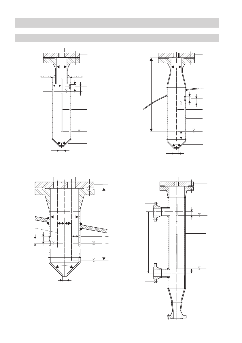
The level electrode is installed inside steam boilers, vessels or in an external level pot. If the electrode
is installed inside the boiler or vessel, a protection tube provided on side ensures correct functioning.
(see section Examples of installation on page 10).
The level electrode can be installed together with one GESTRA level electrode for water level limiting or
for high-level alarm in a single protection tube or external level pot.
Safety note
Danger
When loosening the electrode steam or hot water might escape!
This presents the risk of severe scalding all over the body!
It is therefore essential not to dismantle the electrode unless the boiler pressure is
verified to be 0 bar.
The electrode becomes hot during operation.
Risk of severe burns to hands and arms.
Before carrying out installation and maintenance work make sure that the equipment is
cold.
Attention
The name plate specifies the technical features of the equipment. Do not commission or
operate any item of equipment that does not bear its specific name plate.
The equipment must only be installed, wired and commissioned by qualified and competent staff.
Retrofitting and maintenance work must only be performed by qualified staff who - through adequate
training - have achieved a recognised level of competence.

5
Directives and standards
ATEX (Atmosphère Explosible)
The level electrodes NRG 10-52 and NRG 16-52 are simple items of electrical equipment as specified
in EN 60079-11 section 5.7. According to the European Directive 2014/34/EU the equipment must be
equipped with approved Zener barriers if used in potentially explosive areas. Applicable in Ex zones 1, 2
(1999/92/EG). The equipment does not bear an Ex marking.
VdTÜV Bulletin “Wasserstand 100” (= Water Level 100)
The level electrode NRG 10-52 / NRG 16-52 in conjunction with the following level switches is type ap-
proved according to VdTÜV Bulletin “Wasserstand 100”: NRS 1-52, NRS 1-53, NRS 1-54 and NRS 1-55
or NRS 1-1, NRS 1-2, NRS 1-3 and NRS 1-5.
The VdTÜV Bulletin “Wasserstand (= Water Level) 100” specifies the requirements made on water level
control and limiting equipment for boilers.
Note on the Declaration of Conformity / Declaration by the Manufacturer
For details on the conformity of our equipment according to the European Directives see our Declaration
of Conformity or our Declaration of Manufacturer.
The current Declaration of Conformity / Declaration of Manufacturer are available in the Internet under
www.gestra.com/documents or can be requested from us.

6
TÜV . WR / WB . xx-424
Mat-Nr.:
GESTRA AG Münchener Straße 77 D-28215 Bremen
32bar (464psi)
238°C (460°F)
Tamb = 70°C (158 °F)
NRG 16-52
Betriebsanleitung beachten
See installation instructions
Voirinstructions de montage
Pmax
Tmax
PN40 G 1 1.4571 IP 65
NRG 10-52, NRG 16-52
Technical data
Operating pressure
NRG 10-52: PN 6, 6 bar at 164 °C
NRG 16-52: PN 40, 32 bar at 238 °C
Mechanical connection
Screwed G 1 A, ISO 228
Materials
Screw-in body 1.4571, X6CrNiMoTi17-12-2
Electrode tips 1.4571, X6CrNiMoTi17-12-2
Insulation, spacer disks PTFE
Five-pole connector 3.2161 G AlSi8Cu3
Lengths available
1000 mm, 1500 mm
Electrical connection
Five-pole connectors, cable glands Pg 11
Protection
IP 65 to EN 60529
Max. admissible ambient temperature
Max. 70 °C
Weight
Approx. 1.6 kg (NRG 16-52 L =1000 mm)
Approvals:
TÜV certificate VdTÜV Bulletin “Water Level 100” Requirements made on
water level limiting & control equipment.
Type approval no. TÜV . WR / WB . XX-302; XX-424 (see name plate)
Scope of supply
NRG 10-52
1 Level electrode NRG 10-52, PN 6
1 Joint ring 33 x 39 form D to DIN 7603,
made from 1.4301, bright annealed
1 Installation manual
Name plate/marking
Equipment designation Safety note
Disposal note
CE Marking
Type approval no.
Manufacturer Pressure rating, thread type,
material number
Application
range
Fig. 1
NRG 16-52
1 Level electrode NRG 16-52, PN 40
1 Joint ring 33 x 39 form D to DIN 7603,
made from 1.4301, bright annealed
1 Installation manual

7
Note
One level electrode NRG 10-52 / NRG 16-52 can be installed together with one GESTRA
level electrode, one compact level switch or transmitter in a single protection tube or
external level pot (inside diameter 100 m). Fig. 4 - 7. If the level limiting electrode is
installed inside the vessel, it must be at least 40 mm away from the upper vent hole.
For the approval of the boiler standpipe the relevant regulations must be considered.
Refer to pages 10 for typical installation examples.
If installed outdoors the level electrode must be equipped with a GESTRA weather
protection cover.
The level electrode shall be installed vertically.
The seating surfaces of the standpipe or the flange provided on the vessel must be
accurately machined, see Fig. 3.
Do not bend electrode tips when mounting.
Do not subject electrode tips to physical shocks.
At least 30 mm of the insulating tube must remain on the electrode tips.
Use only the supplied joint ring.
NRG 1.-52: 33 x 39, form D, DIN 7603, 1.4301, bright annealed
Do not lag electrode body above the hexagonal section.
Do not insulate electrode thread with hemp or PTFE tape!
Do not apply conductive paste or grease to the electrode thread!
Make sure that the air distance between the electrode tips and earth (flange, vessel
wall) is not less than 14 mm. Fig. 4 - 7.
Observe the minimum withdrawal distance when installing the electrode!
The specified torques must be strictly observed.
Attention
Tools
Open-end spanner A. F. 41, DIN 3110, ISO 3318
Scriber
Bolt cutter
Flat file, medium cut, DIN 7261, form A
Installation

8
Installation
Dimensions NRG 10-52, NRG 16-52
Fig. 2
NRG 1..-52 with five-pole connector
Fig. 3
3
N8
N10
G1, ISO 228-1
∅40
0.5
1
2
34
A
C
C
260
∅42
1000, 1500
50
≥14
65-70
Screwed G 1 A, ISO 228
1
2
4
5
- continued -

9
Function Function
Please enter function!
Electrode rod/
Connecting terminal
Length [mm]
Please enter length
Electrode body Functional earth
e. g. MIN alarm 1
e. g. pump OFF 2
e. g. pump ON 3
e. g. MAX alarm 4
Installation
NRG 10-52, NRG 16-52, step 1
1. Determine required measuring lengths of electrode tips and enter data in table “Functions”.
2. Use a bolt cutter to cut the four electrode tips 1234.
2. Deburr faces of electrode tips.
3. Strip off 50 mm of PTFE insulation from the ends of the electrode tips. Make sure that the remaining
insulation is at least 30 mm long, measured from the lower edge of the screwed connection.
NRG 10-52, NRG 16-52, step 2
7. Check seating surfaces. Fig. 3
8. Place supplied joint ring 2onto seating surface of the threaded standpipe or flange. Fig. 3
9. Apply a light smear of heat resistant silicone grease (e.g. WINIX®2150) to electrode thread 3.
10. Screw level electrode into threaded standpipe or flange and tighten with an open-end spanner A. F.
41 mm. The torque required when cold is 140 Nm.
1Thermal insulation, provided on site, d = 20 mm (outside of thermal insulation of steam boiler)
2NRG 1..-52: Joint ring 33 x 39, form D, DIN 7603, 1.4301, bright annealed
3Electrode thread
4Insulation of electrode tips
5Electrode tips
Key
Table “Functions”
- continued -

10
Examples of installation
NRG 10-52, NRG 16-52
Fig. 4 Protection tube (provided on site) for
installation inside the boiler
Fig. 5 Protection tube (provided on site) for
installation inside the boiler
Fig. 6 Protection tube (provided on site) for installa-
tion inside the boiler and in combination with
other GESTRA equipment
2
4
20
DN 50
1"
∅20
∅ 20
≤ 90°
c
9
6
7
8
0
a
e
f
DN 100
24,524,5
∅20
G ¾
∅ 20
≤ 90°
≤1500
1"
6
e
a
7
d
g
9
0
c
20
DN 20
DN 20
Centre distance
≤ 20
1"
DN 20
≤20
6
0
9
e
20
∅
20
≥ 10
DN 50
1"
∅ 20
≤1500
9
6
7
0
a
e
f
≤ 90°
≥14
h
8
Fig. 7 External level pot
8

11
Examples of installation
6Flange PN 40, DN 50, DIN EN 1092-01 (single electrode)
Flange PN 40, DN 100, DIN EN 1092-01 (combination of electrodes)
7For the approval of the boiler standpipe with connecting flange the relevant regulations must be
considered.
8Vent hole Provide vent hole as close to the boiler wall as possible!
9High water (HW)
0Electrode tip d = 5 mm
aProtection tube DN 80 (in France according to AFAQ ≥ DN 100)
bProtection tube DN 100
cDistance between electrode rods and protection tube ≥ 14 mm
d
Distance between electrode tips (NRG 1..-50 or NRG 1...-51) ≥ 14 mm (creepage distances
and clearances)
eLow water LW
fReducer DIN 2616-2, K-88.9x3.2-42.4 x 2.6 W
fReducer DIN 2616-2, K-114.3x3.6-48.3 x 2.9 W
hLevel pot ≥ DN 80
Key
- continued -

12
Electrical connection
NRG 10-52, NRG 16-52 with five-pole connector
Fig. 9
iLevel electrode NRG 10-52, NRG 16-52
jRetaining bracket
kLower part of terminal box
lContact block
mScrew
nSealing ring
Key
oUpper part of terminal box
pGasket
qRing
rCable gland
sControl cable
Tools
Screwdriver, size 1
Screwdriver, size 2.5, completely insulated according to DIN VDE 0680-1
i
j
k
lm
n
o
pqr
s

13
Connection of level electrode
To connect the level electrode use screened multi-core control cable with a min. conductor size
0.5 mm2, e. g. LiYCY 5 x 0.5 mm2, max. length: 100 m.
Connect the screen only once to the central earthing point (CEP) in the control cabinet.
Electrical connection
NRG 10-52, NRG 16-52 - connecting the five-pole connector
Please observe the instructions given in the installation & operating manual for the
NRS 1-52, NRS 1-53, NRS 1-54 and NRS 1-55 or NRS 1-1, NRS 1-2, NRS 1-3 and
NRS 1-5.
Make sure that connecting cables leading to the level electrode are segregated and
run separately from power cables.
Check the connection of the screen to the central earthing point (CEP) in the control
cabinet.
Attention
1. Swing up the retaining bracket jand detach the upper part of the terminal box ofrom the level
electrode.
2. Undo screw mand press the contact block lout of the upper part of the terminal box o. Make
sure that you do not lose the sealing ring n.
3. Unscrew cable gland r.
4. Pull cable through cable gland r, ring q, gasket pand upper part of terminal box o.
5. Connect the terminals in the contact block l(Fig. 10) according to table “Functions” on page 9.
6. Press the contact block linto the upper part of the terminal box o.
7. Insert screw m(with sealing ring n) into hole and tighten. In doing so the contact block lis fixed
to the upper part of the terminal box o.
8. Fasten the cable gland r.
9. Plug the upper part ointo the lower part kof the terminal box and secure it in place by swinging
down the retaining bracket j.
Connecting terminals in contact block
Fig. 10
4
3
1
2
- continued -

14
Commissioning, fault indication and troubleshooting
For additional information on commissioning procedures and troubleshooting refer to the installation &
operating manuals for level switch NRS 1-52, NRS 1-53, NRS 1-54 and NRS 1-55 or NRS 1-1, NRS 1-2,
NRS 1-3 and NRS 1-5!
If faults occur that are not listed above or cannot be corrected, please contact our service centre or
authorized agency in your country.
Removing and disposing of the level electrode
Removing and disposing of level electrode NRG 10-52 / NRG 16-52
1. Undo screw m. Fig. 9
2. Detach upper part of the terminal box ofrom the level electrode.
3. Before removing the equipment make sure that is is neither hot nor under pressure.
For the disposal of the equipment observe the pertinent legal regulations concerning waste disposal.
Danger
When loosening the electrode steam or hot water might escape!
This presents the risk of severe scalding all over the body!
It is therefore essential not to dismantle the electrode unless the boiler pressure is
verified to be 0 bar.
The electrode becomes hot during operation.
Risk of severe burns to hands and arms.
Before carrying out installation and maintenance work make sure that the equipment is
cold.

15
For your Notes

819123-02/03-2017cm (808842-02) · GESTRA AG · Bremen · Printed in Germany
GESTRA AG
Münchener Straße 77
28215 Bremen
Germany
Telefon +49 421 3503-0
Telefax +49 421 3503-393
E-mail [email protected]
Web www.gestra.de
Agencies all over the world: www.gestra.de
Other manuals for NRG 10-52
1
This manual suits for next models
1
Table of contents
Other GESTRA Measuring Instrument manuals

GESTRA
GESTRA NRG 26-21 Manual

GESTRA
GESTRA SRL 6-60 User manual

GESTRA
GESTRA NRS 1-50 User manual

GESTRA
GESTRA VK 14 User manual

GESTRA
GESTRA NRG 211-1 User manual

GESTRA
GESTRA NRG 16-51 User manual

GESTRA
GESTRA NRG 16-38 S User manual

GESTRA
GESTRA NRT 2-1 Quick guide

GESTRA
GESTRA LRGT 16-1 Manual

GESTRA
GESTRA LRG 16-40 User manual