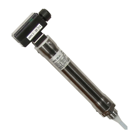
GESTRA NRG 16-51 User manual

Level Electrodes
NRG 16-51
NRG 17-51
NRG 19-51
Original Installation &
Operating Manual
850692-00
EN (USA)
English

2NRG 16-51, NRG 17-51, NRG 19-51 - USA - Installation & Operating Manual - 850692-00
Contents
Content of this Manual......................................................................................................................... 4
Scope of supply, product package....................................................................................................... 4
How to use this Manual........................................................................................................................ 5
Illustrations and symbols used............................................................................................................ 5
Hazard symbols in this Manual............................................................................................................ 5
Types of warning .................................................................................................................................. 6
Specialist terms, abbreviations ........................................................................................................... 7
Usage for the intended purpose........................................................................................................... 8
Applicable directives and standards.............................................................................................. 8
Admissible system components....................................................................................................... 8
Improper use ........................................................................................................................................ 8
Basic safety information ...................................................................................................................... 9
Required personnel qualifications..................................................................................................... 10
Notes on product liability................................................................................................................... 10
Function .............................................................................................................................................. 11
Technical data .................................................................................................................................... 12
Rating plate, identification................................................................................................................. 13
Overall view of the NRG 16-51, NRG 17-51, NRG 19-51 .................................................................... 14
Dimensions of the NRG 16-51, NRG 17-51, NRG 19-51 with four-pole connector ........................... 15
Overall view of the NRG 16-51F, NRG 17-51F, NRG 19-51F................................................................ 16
Dimensions of the NRG 16-51F, NRG 17-51F, NRG 19-51F with aluminum terminal box................. 17
Preparing for installation ................................................................................................................... 18
Installation.......................................................................................................................................... 19
Installing the NRG 16-51, NRG 17-51, NRG 19-51, step 1 .............................................................. 21
Installing the NRG 16-51, NRG 17-51, NRG 19-51, step 2 .............................................................. 22
Installing the NRG 16-50F, NRG 17-50F, NRG 19-50F with aluminum terminal box......................... 23
Installing the NRG 16-50F, NRG 17-50F, NRG 19-50F, additional information .................................. 24
3NRG 16-51, NRG 17-51, NRG 19-51 - USA - Installation & Operating Manual - 850692-00
Contents
Installation examples with dimensions............................................................................................. 25
Electrical connection.......................................................................................................................... 27
NRG 16-50, NRG 17-50, NRG 19-50 with four-pole connector........................................................ 27
Connecting the level electrode....................................................................................................... 28
NRG 16-50, NRG 17-50, NRG 19-50 with four-pole connector........................................................ 28
NRG 16-50F, NRG 17-50F, NRG 19-50F with aluminum terminal box.............................................. 28
Wiring diagram .............................................................................................................................. 29
Bringing into service, fault indications and troubleshooting ........................................................... 30
Taking out of service.......................................................................................................................... 30
Removing the NRG 1..-51 level electrode....................................................................................... 30
Removing the NRG 1..-51F level electrode..................................................................................... 30
Disposal .............................................................................................................................................. 31
Returning decontaminated equipment.............................................................................................. 31
UL components................................................................................................................................... 31

4NRG 16-51, NRG 17-51, NRG 19-51 - USA - Installation & Operating Manual - 850692-00
Content of this Manual
Product:
■ Level Electrodes NRG 16-51, NRG 17-51, NRG 19-51
First edition:
BAN 850692-00/08-2021cm
© Copyright
All rights reserved. Any misuse, particularly reproduction and dissemination to third parties, is not
permitted. The General Terms & Conditions of GESTRA AG apply.
Scope of supply, product package
NRG 16-51
1 level electrode NRG 16-51
1 washer with set screw
(enlarged measuring surface) (optional)
1 retaining ring (optional)
1 Installation & Operating Manual
NRG 17-51
1 level electrode NRG 17-51
1 washer with set screw
(enlarged measuring surface) (optional)
1 retaining ring (optional)
1 Installation & Operating Manual
NRG 19-51
1 level electrode NRG 19-51
1 washer with set screw
(enlarged measuring surface) (optional)
1 retaining ring (optional)
1 Installation & Operating Manual

5NRG 16-51, NRG 17-51, NRG 19-51 - USA - Installation & Operating Manual - 850692-00
How to use this Manual
This Installation & Operating Manual describes the correct use of NRG 1..-51 level electrodes.
It applies to persons who integrate this equipment in control systems, install, bring into service,
operate, maintain and dispose of this equipment. Anyone carrying out the above-mentioned
activities must have read this Installation & Operating Manual and understood its contents.
■ Read this Manual in full and follow all instructions.
■ Please also read the instructions for use of any accessories.
■ The Installation & Operating Manual is part of the product package. Keep it in an easily
accessible location.
Availability of this Installation & Operating Manual
■ Make sure this Installation & Operating Manual is always available to the operator.
■ If you pass on or sell the equipment to a third party, please also hand over the Installation &
Operating Manual.
Hazard symbols in this Manual
Danger zone, dangerous situation
Illustrations and symbols used
1. Action to be taken
2.
■ Lists
◆ Bullet points in lists
A Keys to illustrations
Additional
information
Read the relevant
Installation & Operating Manual

6NRG 16-51, NRG 17-51, NRG 19-51 - USA - Installation & Operating Manual - 850692-00
Types of warning
DANGER
Warning of a dangerous situation that results in death or serious injury.
WARNING
Warning of a dangerous situation that may possibly result in death or serious injury.
CAUTION
Warning of a situation that may result in minor or moderate injury.
ATTENTION
Warning of a situation that results in damage to property or the environment.

7NRG 16-51, NRG 17-51, NRG 19-51 - USA - Installation & Operating Manual - 850692-00
Specialist terms, abbreviations
Here, we explain some abbreviations, specialist terms, etc., which are used in this Manual.
NRGT .. / NRR.. / NRS.. / URS .. / URB .. / SRL .. / etc.
Equipment and type designations of GESTRA AG.
SELV
Safety Extra Low Voltage
Operating point (of the plant)
The operating point describes the operating parameters within which a plant or boiler is operated
in its nominal range. In a steam boiler, for example, these parameters would be output, pressure,
and temperature.
The design data may be a lot more stringent, however.
A boiler that is operated at 145psi (10bar) and 356°F (180°C) may be designed to withstand a
pressure of 870psi (60bar) and a temperature of 527°F (275°C), for example, which is therefore
not necessarily its operating point.

8NRG 16-51, NRG 17-51, NRG 19-51 - USA - Installation & Operating Manual - 850692-00
Usage for the intended purpose
NRG 1...-51 level electrodes are used in conjunction with the NRS 1-51 level switch as a
high-level alarm for steam boilers and hot water installations.
A high-level alarm prevents the defined high water (HW) level from being exceeded and switches
off the feedwater supply, for example, to achieve this.
The equipment has been tested and approved for use in the scope governed by the following
directives and standards:
Standards:
■UL 60730-1 and CAN/CSA E60730-1
General Requirements for Automatic Electrical Controls
■UL 60730-2-15 and CAN/CSA E60730-2-15
Requirements for Automatic Electrical Water Level Sensing Controls
Applicable directives and standards
Improper use
There is a danger of death due to explosion if the equipment is used in potentially
explosive atmospheres.
Do not use the equipment in potentially explosive atmospheres.
Do not bring any equipment into service that does not have its own specific rating
plate.
The rating plate indicates the technical features of the equipment.
Admissible system components
According to UL 60730-2-15, the NRG 1...-51 level electrode can be operated with the NRS 1-51
level switch and regarded as a protective control.
To ensure proper use in all applications, please also read the Installation & Operating
Manuals for the system components used.
■ You can find the latest Installation & Operating Manuals for other system compo-
nents on our website:
http://www.gestra.com

9NRG 16-51, NRG 17-51, NRG 19-51 - USA - Installation & Operating Manual - 850692-00
Danger to life from scalding! Do not remove the level electrode under pressure.
Steam or hot water can spurt forcefully out of the equipment.
■ Only remove the level electrode at 0psi (0bar) boiler pressure.
Risk of severe burns! Do not perform work on a level electrode that is still hot.
The level electrode gets very hot during operation.
■ Allow the level electrode to cool.
■ Always wait for the level electrode to cool before performing any installation and
maintenance work.
There is a risk of electric shock during work on electrical systems.
■ Always switch off the voltage to the plant before performing connection work.
■ Check that the plant is not carrying live voltage before commencing work.
Danger to life! Hot steam or hot water can suddenly escape from a faulty
NRG 1...-51 level electrode.
Shocks and impacts during transport or installation can result in damage to or leaks in
the level electrode, causing pressurized hot steam or hot water to escape through the
pressure relief hole.
■ To prevent damage during transport and installation, do not expose the electrode
rod to major shocks or impacts.
■ Before and after installation, check that the level electrode is completely undamaged.
■ Check that the level electrode is not leaking when bringing into service.
Attempts to repair the equipment will cause the plant to become unsafe.
■ The NRG 1...-51 level electrode may only be repaired by the manufacturer,
GESTRA AG.
■ Only replace faulty equipment with identical equipment from GESTRA AG.
Basic safety information

10 NRG 16-51, NRG 17-51, NRG 19-51 - USA - Installation & Operating Manual - 850692-00
Required personnel qualifications
Activity Personnel
Integration in control system Specialist staff Plant designer
Installation /
electrical connection/
bringing into service
Specialist staff
The equipment may only be installed, wired
and brought into service by qualified and
competent staff.
Operation Boiler service technician Staff trained by the plant operator.
Maintenance work Specialist staff
Fitting and maintenance work may only be
performed by authorized staff who have
undergone specific training.
Refits Specialist staff Persons trained by the plant operator to work
with pressure and temperature.
Fig. 1
Notes on product liability
The manufacturer cannot accept any liability for damages resulting from improper use of the
equipment.

11NRG 16-51, NRG 17-51, NRG 19-51 - USA - Installation & Operating Manual - 850692-00
When the water exceeds the high water level, the level electrode is immersed and an alarm is
triggered in the NRS 1-51 level switch. This “High water (HW) exceeded” switchpoint is deter-
mined by the length of the electrode extension.
The level electrode uses the conductivity of the water to measure the water level, and is
self-monitoring, i.e. an alarm is also triggered if the electrode insulator is leaking or contaminated
and/or there is a fault in the electrical connection.
Please note that a suitable protective tube needs to be provided on site during installation to
ensure safe operation. One NRG 1...-51 level electrode can be installed in a single protective tube
or level pot together with a GESTRA level electrode for water level limitation.
If the level electrode is installed in a level pot outside the boiler, the connection pipes must be
flushed regularly. The manufacturer recommends connection pipes of ≥ 1.57in (40mm) for
steam and ≥ 3.94in (100mm) for water. If smaller connection pipes are used, these must have
a minimum NPS of 1inch. The level pot must have a suitable flushing device at its lowest point.
This device flushes the connection pipes to the boiler and enables the function of the water level
limiter to be tested. No shut-off valves of any type shall be placed in the piping between the boiler
and the low water cutoff.
Safety information
The equipment is part of a protective control according to UL 60730-1 and may only be installed,
electrically connected and brought into service by qualified and competent staff.
Fitting and maintenance work may only be performed by authorized staff who have undergone
specific training.
Attention
The rating plate indicates the technical features of the equipment. Do not bring into
service or operate any equipment that does not bear its own specific rating plate.
Danger
Please note that a suitable protective tube needs to be provided on site for an elec-
trode installed internally, to ensure safe operation. Please exercise caution when
flushing the system, as outflowing boiler water or flash steam can lead to scalding.
Please wear suitable protective clothing and do not touch any hot surfaces.
Function

12 NRG 16-51, NRG 17-51, NRG 19-51 - USA - Installation & Operating Manual - 850692-00
NRG 16-51, NRG 17-51, NRG 19-51
Technical data
Service pressure
NRG 16-51: 464psi at 460°F (32bar at 238°C)
NRG 17-51: 667psi at 500 °F (46bar at 260 °C)
NRG 19-51: 1450psi at 592 °F (100bar at 311 °C)
Mechanical connection
Thread 1" - 11.5 NPT
Materials
Screw-in body 1.4404/ F316L
Measuring electrode 1.4571, X6CrNiMoTi17-12-2
Electrode extension 1.4401, X5CrNiMo17-12-2
Electrode insulation PEEK
NRG 1...-51: Four-pole connector, polyamide (PA)
NRG 1...-51F: Terminal box 3.2161 G AlSi8Cu3
Lengths supplied
19.68in (500mm), 39.37in (1000mm), 59.05in (1500mm)
Electrical connection
NRG 1...-51: Four-pole connector, cable glands M 16
NRG 1...-51F: Aluminum terminal box, cable gland M 20
Protection
IP 65 according to EN 60529
NRG 1...-51: NEMA type 1 according to NEMA 250
NRG 1...-51F: NEMA type 4 according to NEMA 250
Admissible ambient temperature
Max. 158°F (70°C)
Weight
Approx. 2.65lb (1.2kg) (without extension) (NRG 16-51, NRG 17-51, NRG 19-51)
Approx. 4.63lb (2.1kg) (without extension) (NRG 16-51F, NRG 17-51F, NRG 19-51F)
Other information
Incorporated type 1 action operating control
Pollution degree 3, impulse voltage 330V

13NRG 16-51, NRG 17-51, NRG 19-51 - USA - Installation & Operating Manual - 850692-00
464psi (32bar)
460°F (238°C)
NRG 16-51
Pmax
Tmax
1"-11,5NPT 1.4404/F316L IP65
Betriebsanleitung beachten
See installation instructions
Voir instructions de montage
MAX
GESTRA AG 28215 Bremen GERMANY
Tamb = 158°F (70°C)T
667psi (46bar)
500°F (260°C)
NRG 17-51
Pmax
Tmax
Betriebsanleitung beachten
See installation instructions
Voir instructions de montage
MAX
GESTRA AG 28215 Bremen GERMANY
1"-11,5NPT 1.4404/F316L IP65
Tamb = 158°F (70°C)T
1450psi (100bar)
592°F (311°C)
NRG 19-51
Pmax
Tmax
Betriebsanleitung beachten
See installation instructions
Voir instructions de montage
MAX
GESTRA AG 28215 Bremen GERMANY
1"-11,5NPT 1.4404/F316L IP65
Tamb = 158°F (70°C)T
464psi (32bar)
460°F (238°C)
NRG 16-50
Betriebsanleitung beachten
See installation instructions
Voir instructions de montage
Pmax
Tmax
MIN
1"-11,5NPT 1.4404/F316L IP65
GESTRA AG 28215 Bremen GERMANY
Tamb = 158°F (70°C)T
NRG 17-50
Pmax
Tmax
MIN Betriebsanleitung beachten
See installation instructions
Voir instructions de montage
GESTRA AG 28215 Bremen GERMANY
870psi (60bar)
527°F (275°C)
1"-11,5NPT 1.4404/F316L IP65
Tamb = 158°F (70°C)T
1450psi (100bar)
592°F (311°C)
NRG 19-50
Pmax
Tmax
MIN Betriebsanleitung beachten
See installation instructions
Voir instructions de montage
GESTRA AG 28215 Bremen GERMANY
1"-11,5NPT 1.4404/F316L IP65
Tamb = 158°F (70°C)T
Betriebsanleitung
beachten
See installation instructions
Hier öffnen
Open here
Ouvrir ici
Voir instructions de
montage
NRG 17 - 50 F
NRG 19 - 50 F
NRG 16 - 50 F
1"-11,5NPT 1.4404/F316L IP65
870psi (60bar)
527°F (275°C)
464psi (32bar)
460°F (238°C)
1450psi (100bar)
592°F (311°C)
Pmax
Tmax
Tamb = 158°F (70°C )T
GESTRA AG
Münchener Str. 77
28215 Bremen
Made in Germany
NRG 17 - 51 F
NRG 19 - 51 F
NRG 16 - 51 F
1"-11,5NPT 1.4404/316L IP65
667psi (46bar)
500°F (260°C)
464psi (32bar)
460°F (238°C)
1450psi (100bar)
592°F (311°C)
Betriebsanleitung
beachten
See installation instructions
Hier öffnen
Open here
Ouvrir ici
Voir instructions de
montage
Pmax
Tmax
GESTRA AG
Münchener Str. 77
28215 Bremen
Made in Germany
Tamb = 158°F (70°C)T
Rating plate, identification
Fig. 1
Fig. 2
Equipment designation Safety information
Disposal information
CE marking
Pressure rating, thread type, material
number, type approval number
Manufacturer Serial number
Equipment designation, pressure rating
Information on pressure / temp. limit
CE marking, type approval number
Thread type, material number, protection
Safety information
Disposal information
Manufacturer
Serial number
464psi (32bar)
460°F (238°C)
NRG 16-51
Pmax
Tmax
1"-11,5NPT 1.4404/F316L IP65
Betriebsanleitung beachten
See installation instructions
Voir instructions de montage
MAX
GESTRA AG 28215 Bremen GERMANY
Tamb = 158°F (70°C)T
667psi (46bar)
500°F (260°C)
NRG 17-51
Pmax
Tmax
Betriebsanleitung beachten
See installation instructions
Voir instructions de montage
MAX
GESTRA AG 28215 Bremen GERMANY
1"-11,5NPT 1.4404/F316L IP65
Tamb = 158°F (70°C)T
1450psi (100bar)
592°F (311°C)
NRG 19-51
Pmax
Tmax
Betriebsanleitung beachten
See installation instructions
Voir instructions de montage
MAX
GESTRA AG 28215 Bremen GERMANY
1"-11,5NPT 1.4404/F316L IP65
Tamb = 158°F (70°C)T
464psi (32bar)
460°F (238°C)
NRG 16-50
Betriebsanleitung beachten
See installation instructions
Voir instructions de montage
Pmax
Tmax
MIN
1"-11,5NPT 1.4404/F316L IP65
GESTRA AG 28215 Bremen GERMANY
Tamb = 158°F (70°C)T
NRG 17-50
Pmax
Tmax
MIN Betriebsanleitung beachten
See installation instructions
Voir instructions de montage
GESTRA AG 28215 Bremen GERMANY
870psi (60bar)
527°F (275°C)
1"-11,5NPT 1.4404/F316L IP65
Tamb = 158°F (70°C)T
1450psi (100bar)
592°F (311°C)
NRG 19-50
Pmax
Tmax
MIN Betriebsanleitung beachten
See installation instructions
Voir instructions de montage
GESTRA AG 28215 Bremen GERMANY
1"-11,5NPT 1.4404/F316L IP65
Tamb = 158°F (70°C)T
Betriebsanleitung
beachten
See installation instructions
Hier öffnen
Open here
Ouvrir ici
Voir instructions de
montage
NRG 17 - 50 F
NRG 19 - 50 F
NRG 16 - 50 F
1"-11,5NPT 1.4404/F316L IP65
870psi (60bar)
527°F (275°C)
464psi (32bar)
460°F (238°C)
1450psi (100bar)
592°F (311°C)
Pmax
Tmax
Tamb = 158°F (70°C )T
GESTRA AG
Münchener Str. 77
28215 Bremen
Made in Germany
NRG 17 - 51 F
NRG 19 - 51 F
NRG 16 - 51 F
1"-11,5NPT 1.4404/316L IP65
667psi (46bar)
500°F (260°C)
464psi (32bar)
460°F (238°C)
1450psi (100bar)
592°F (311°C)
Betriebsanleitung
beachten
See installation instructions
Hier öffnen
Open here
Ouvrir ici
Voir instructions de
montage
Pmax
Tmax
GESTRA AG
Münchener Str. 77
28215 Bremen
Made in Germany
Tamb = 158°F (70°C)T
A
B
C
D
43 21
4-441716-00
Typenschild UL
NRG 1x-51F
NPT-Version
-
CorelDraw X8
-
Kulmann
2021-06-30
Examiner
Designer
Drawer
Scale
Refer to protection
notice ISO 16016!
1:1
No Änderung/Modification Datum/Date Geänd/Modif. PrüferKonstr.
Datum/Date Name/Name
Nr./No
Ersatz für/Replaces Ersetzt durch/Replaced by
Ersteller/
Konstrukteur/
Prüfer/
Schutzvermerk
ISO 16016 beachten!
2021-06-30
200 - -
Audehm
Maßstab/
Nr./ M-Nr.
Free size tolerance
ISO 2768 mk
Freimaßtoleranzen
ISO 2768 mk
GESTRAGESTRA
Input rating: Up to 5VAC
Ambient temperature: 32 158°F (0 70°C)--
Environmental rating: NEMA 4 / 4X / 12
Wiring: Use Copper Conductors Only,
Use 60/75°C Conductors,
Use No.18 16 AWG Wire Size Only,-
Tightening: Torque 0.79 Nm or 7 lb in.
Use with accessory: NRS1 51-
100
34
OPERATING CONTROL
E513189
A
B
C
D
43 21
4-441714-00
Typenschild UL
NRG 1x-51
NPT-Version
-
CorelDraw X8
-
Kulmann
2021-06-30
Examiner
Designer
Drawer
Scale
Refer to protection
notice ISO 16016!
1:1
No Änderung/Modification Datum/Date Geänd/Modif. PrüferKonstr.
Datum/Date Name/Name
Nr./No
Ersatz für/Replaces Ersetzt durch/Replaced by
Ersteller/
Konstrukteur/
Prüfer/
Schutzvermerk
ISO 16016 beachten!
2021-06-30
200 - -
Audehm
Maßstab/
Nr./ M-Nr.
Free size tolerance
ISO 2768 mk
Freimaßtoleranzen
ISO 2768 mk
GESTRAGESTRA
Input rating: Up to 5VAC
Ambient temperature: 32 158°F (0 70°C)--
Environmental rating: NEMA 1
Wiring: Use Copper Conductors Only,
Use 60/75°C Conductors,
Use No.18 16 AWG Wire Size Only,-
Tightening: Torque 0.79 Nm or 7 lb in.
Use with accessory: NRS1 51-
100
34
OPERATING CONTROL
E513189
Fig. 3 NRG 1...-51F Fig. 4 NRG 1...-51

14 NRG 16-51, NRG 17-51, NRG 19-51 - USA - Installation & Operating Manual - 850692-00
Overall view of the
NRG 16-51, NRG 17-51, NRG 19-51
Fig. 5
B
A
C
E
F
D
ATerminal box or four-pole connector
BCable entry
CCover tube
DElectrode thread
Key
EMeasuring electrode
FElectrode extension
GEnlarged measuring surface
G

15NRG 16-51, NRG 17-51, NRG 19-51 - USA - Installation & Operating Manual - 850692-00
Dimensions of the NRG 16-51, NRG 17-51, NRG 19-51
with four-pole connector
Fig. 6
NRG 16-51, NRG 17-51
with enlarged measuring surface
≤59.05 in
(1500 mm)
3.54 in
(90 mm) 10.71 in (272 mm)
1" - 11.5 NPT
0.38 in (8 mm)
0.91 in (23 mm)
Thermal insulation
provided on site
0.8 in (20 mm)
Fig. 7
NRG 19-51
5.9 in
(150 mm) 11.18 in (284 mm)
1" - 11.5 NPT
0.8 in (20 mm)
0.38 in (8 mm)
≤59.05 in
(1500 mm)
Size 41

16 NRG 16-51, NRG 17-51, NRG 19-51 - USA - Installation & Operating Manual - 850692-00
Overall view of the NRG 16-51F, NRG 17-51F, NRG 19-51F
Fig. 8
ATerminal box or four-pole connector
BCable entry
CCover tube
DElectrode thread
Key
EMeasuring electrode
FElectrode extension
A
B
D
E
F
C

17NRG 16-51, NRG 17-51, NRG 19-51 - USA - Installation & Operating Manual - 850692-00
Dimensions of the NRG 16-51F, NRG 17-51F, NRG 19-51F
with aluminum terminal box
Fig. 9
NRG 16-51F, NRG 17-51F
Fig. 10
NRG 19-51F
13.35 in (338 mm)
13.78 in (350 mm)
1" - 11.5 NPT 1" - 11.5 NPT
5.5 in (140 mm)
5.5 in
(140 mm)
w = 2.76 in (70 mm)
6.9 in (175 mm)
w = 2.76 in (70 mm)
5.9 in
(150 mm)
≤59.05 in
(1500 mm)
3.54 in
(90 mm)
≤59.05 in
(1500 mm)
Size 41
Thermal insulation
provided on site
Thermal insulation
provided on site
0.8 in (20 mm)
0.8 in (20 mm)

18 NRG 16-51, NRG 17-51, NRG 19-51 - USA - Installation & Operating Manual - 850692-00
Preparing for installation
If the equipment is to be installed outdoors, outside the protection of a building,
environmental influences may adversely affect function.
■ Pay attention to the permitted ambient conditions in the technical data,
see page 12.
■ Do not operate the equipment if the temperature is below freezing.
◆ At temperatures below freezing, use a suitable heat source (e.g. control cabinet
heater, etc.).
■ Connect all parts of the plant to a central grounding point to prevent equalizing
currents.
■ Use a cover to protect the equipment from direct sunlight, condensation and
heavy rain.
■ Use UV-resistant cable ducts for routing the connecting cable.
■ Take further measures to protect the equipment from lightning, insects and
animals, and salty air.
You will need the following tools:
■Open-ended wrench size 13
■Open-ended wrench size 19
■Open-ended wrench size 41
■Scriber
■Hacksaw
■Flat file

19NRG 16-51, NRG 17-51, NRG 19-51 - USA - Installation & Operating Manual - 850692-00
You will need the following tools:
Note
■One NRG 1...-51 level electrode can be installed in a single protective tube or
level pot (inside diameter 3.94in [100mm]) together with a GESTRA level elec-
trode, a level switch or transmitter for water level control and limitation. Fig. 18.
If a NRG 1...-50 level electrode is used (for water level limitation) and installed
inside the vessel, it must be at a minimum distance of 1.57in (40mm) from the
upper pressure relief hole.
■Check the boiler standpipe and flange during the preliminary boiler inspection.
■Installation examples can be found on pages 25 and 26.
■The electrode must not be at an incline of more than 45°, and the length of the
electrode rod is limited to 39.37in (1000mm).
■For outdoor installations, please use the NRG 1...-51F level electrode. Type F
level electrodes have an aluminum terminal box.
Installation
DANGER
Danger to life! Escaped hot steam can cause scalding.
Hot steam or hot water can escape suddenly if the level electrode is unscrewed under
pressure.
■ Reduce the boiler pressure to 0psi (0bar) and check the pressure before unscrewing
the level electrode.
■ Only remove the level electrode at 0psi (0bar) boiler pressure.
WARNING
The hot level electrode can cause severe burns.
The level electrode gets very hot during operation.
■ Always let the level electrode cool down before performing installation and maintenance
work.
■ Only remove level electrodes that have cooled down.
ATTENTION
Incorrect installation can lead to malfunctions in the plant or the level electrode.
■Take care not to bend the measuring electrode during installation!
■Do not lag the terminal head Aor cover tube B(see pages 14 and 16) when
thermally insulating the boiler!
■Do not coat the electrode thread with conductive paste or grease!
■Make sure there is a creepage path of at least 0.55in (14mm) between the electrode
and ground (flange, tank wall). Figs. 17 - 19
■If the electrode is installed inside the vessel, it must be at least 1.57in (40mm) away
from the pressure relief hole in the protective tube.

20 NRG 16-51, NRG 17-51, NRG 19-51 - USA - Installation & Operating Manual - 850692-00
Installation
Fig. 12
1
2
3
4
0
a
Fig. 13
NRG 16-51
NRG 17-51
NRG 19-51
56
7
Fig. 11
This manual suits for next models
5
Table of contents
Other GESTRA Measuring Instrument manuals

GESTRA
GESTRA SRL 6-60 User manual

GESTRA
GESTRA VK 14 User manual

GESTRA
GESTRA NRT 2-1 Quick guide

GESTRA
GESTRA LRGT 16-1 Manual

GESTRA
GESTRA NRG 26-21 Manual

GESTRA
GESTRA LRG 16-40 User manual

GESTRA
GESTRA NRG 16-38 S User manual

GESTRA
GESTRA NRG 10-52 User manual

GESTRA
GESTRA LRG 16-4 Installation instructions

GESTRA
GESTRA NRG 211-1 User manual
Popular Measuring Instrument manuals by other brands

S+S Regeltechnik
S+S Regeltechnik PREMASREG 711 Series Operating Instructions, Mounting & Installation

THORLABS
THORLABS INTUN TL 1550-T manual

VWR
VWR MD 8000 H operating manual

Siemens
Siemens Sitrans F Series operating instructions

Dranetz-BMI
Dranetz-BMI POWER XPLORER Series Quick reference guide

Fluke
Fluke 972A user manual