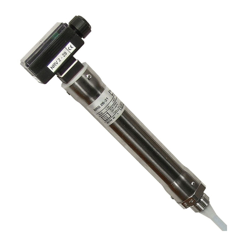
GESTRA LRGT 16-1 Manual

1
LRGT 16-1
LRGT 16-2
LRGT 17-1
Installation & Operating Instructions
818726-06
Conductivity Transmitter LRGT 16-1
Conductivity Transmitter LRGT 16-2
Conductivity Transmitter LRGT 17-1
GESTRA Steam Systems
EN
English

2
Contents
Page
Important notes
Intended use...........................................................................................................................................4
Function .................................................................................................................................................4
Safety note..............................................................................................................................................5
Directives and standards
EU Pressure Equipment Directive 2014/68/EU.........................................................................................6
VdTÜV Bulletin "Wasserüberwachung 100" (= Water Monitoring 100).....................................................6
Approval for Marine Use..........................................................................................................................6
LV (Low Voltage Directive) and EMC (Electromagnetic Compatibility)........................................................6
ATEX (Atmosphère Explosible) .................................................................................................................6
UL/cUL (CSA) approval ............................................................................................................................6
Notes on the Declaration of Conformity/Manufacturer's Declaration ........................................................6
Technical data
LRGT 16-1, LRGT 16-2, LRGT 17-1 .........................................................................................................7
Scope of supply ......................................................................................................................................9
Name plate/marking ...............................................................................................................................9
Installation
Dimensions of LRGT 16-1, LRGT 16-2, LRGT 17-1 ................................................................................10
Key .......................................................................................................................................................11
Tools.....................................................................................................................................................11
Installation
Mounting the conductivity transmitter ...................................................................................................12
Installation examples
LRGT 16-1, LRGT 16-2, LRGT 17-1 .......................................................................................................13
Key .......................................................................................................................................................14

3
Contents
Page
Electrical connection
LRGT 16-1, LRGT 16-2, LRGT 17-1 .......................................................................................................15
Connection of conductivity transmitter ..................................................................................................15
Connecting LRGT 16-1, LRGT 16-2, LRGT 17-1.....................................................................................16
Key .......................................................................................................................................................16
Wiring diagram for conductivity transmitter LRGT 16-1, LRGT 17-1.......................................................17
Wiring diagram for conductivity transmitter LRGT 16-2 .........................................................................17
Safety power supply unit for LRGT 16-1, LRGT 16-2, LRGT 17-1 ...........................................................18
Tools.....................................................................................................................................................18
Factory settings ..................................................................................................................................18
Commissioning procedure
Switch on mains voltage and open the terminal box..............................................................................19
Establishing the measuring range and actual value output ....................................................................19
Checking the setting of temperature coefficient TK....................................................................................................................20
Operation
Correcting the measured value..............................................................................................................21
Adjusting the cell constant ....................................................................................................................21
Function test.........................................................................................................................................22
LED indicator ........................................................................................................................................22
Fault indications and troubleshooting
Indications, diagnosis and remedies......................................................................................................23
Checking the electronic circuit board ...................................................................................................25
Replacing the electronic circuit board ...................................................................................................25
Maintenance
Safety note............................................................................................................................................26
Cleaning the measuring electrode .........................................................................................................26
Removing and disposing of the conductivity transmitter
Removing and disposing of conductivity transmitters LRGT 16-1, LRGT 16-2, LRGT 17-1......................27
continued

4
Important notes
Intended use
Use conductivity transmitters LRGT 16-1, LRGT 16-2 and LRGT 17-1 only for measuring electrical
conductivity in liquids.
Conductivity transmitters LRGT 16-1 / LRGT 16-2/17-1 can be used as conductivity limiters or
continuous blowdown controllers in steam boilers in combination with the following equipment:
Conductivity controller LRR 1-51
Conductivity controller LRR 1-53
Industrial controller KS 90-1
To guarantee trouble-free operation, observe the requirements made on water as specified
in the pertinent TRD and EN regulations.
The equipment may only be used within the admissible pressure and temperature ratings.
Function
The compact conductivity transmitters LRGT 16-1, LRGT 16-2, LRGT 17-1 consist of a conductivity
electrode, a temperature sensor for detecting the liquid temperature, and an electronic circuit board
incorporated in the terminal box.
Conductivity transmitters LRGT 16-1, LRGT 17-1 use the conductometric measuring method with
two measuring electrodes, while transmitter LRGT 16-2 uses the conductometric technique with four
measuring electrodes. The equipment measures the electrical conductivity of electrically conductive
fluids (TDS = Total Dissolved Solids content), and provides a 4-20 mA measuring current as a function
of the detected conductivity value.
LRGT 16-1, LRGT 17-1
A measuring current of variable frequency passes through the fluid, creating a potential gradient
between the measuring electrode and the measuring tube, which is then used as measuring voltage UU.
LRGT 16-2
The conductivity electrode consists of two current and two voltage electrodes. The current electrodes
direct the measuring current UIinto the fluid at a fixed frequency, thereby creating a potential gradi-
ent between these electrodes. This potential gradient is then picked up by the voltage electrodes and
evaluated as measuring voltage UU.
LRGT 16-1, LRGT 17-1 and LRGT 16-2
The electrical conductivity is a function of the temperature. In order to base the measured values on a
reference temperature, a resistance thermometer integrated in the electrode therefore measures the
fluid temperature.
The electrical conductivity is calculated from measuring voltages UUand UIand – as a function of the
adjusted temperature coefficient Tk– based linearly on the reference temperature of 25°C. Once it has
been converted into a current signal proportional to the conductivity, an output current of 4-20 mA is
available for external further processing.
The cables leading to the measuring electrode, the measuring tube and the resistance thermometer
are monitored and checked for open and short circuit. In addition, the circuit board is protected against
excess temperatures in the terminal box. In the event of a malfunction, the LEDs light up or flash and
the current signal is set to 0 or 0.5 mA.
The code switch enables configuration of the transmitter, the adaptation of the cell constant and activa-
tion of a function test. Electrical conductivity is measured in µS/cm. In some countries, ppm (parts per
million) is used instead. 1 µS/cm = 0.5 ppm.
5
Important notes
Function
The conductivity transmitters are used as conductivity limiters and continuous blowdown controllers in
steam boilers in combination with the following equipment:
Conductivity controller LRR 1-51
Conductivity controller LRR 1-53
Industrial controller KS 90-1
Conductivity transmitters LRGT 16-1, LRGT 17-1 are mainly used in steam boilers with low TDS
content, e.g. steam regenerators, high-pressure boilers and condensate tanks.
Conductivity transmitter LRGT 16-2 is mainly used in industrial boilers up to PN 40 and
max. admissible conductivities of 6000 µS/cm in accordance with TRD/EN.
In steam and water boilers, conductivity transmitters/controllers can also be used to monitor the
condensate, feedwater and the water circuit for the ingress of acids, alkalis or seawater (EN 12952-7,
EN 12953-6, TRD 604, page 1).
Attention
The name plate specifies the technical features of the equipment. Do not commission or
operate any item of equipment that does not bear its own specific name plate.
Safety note
Danger
Steam or hot water can escape when the conductivity transmitter is loosened.
This presents a risk of severe scalding all over the body!
Therefore, only dismantle the conductivity transmitter when the boiler pressure is 0 bar.
The conductivity transmitter becomes hot during operation.
Risk of severe burns to hands and arms.
Make sure that equipment is cold before carrying out installation and maintenance work.
The equipment may only be installed, wired and commissioned by qualified and competent staff.
Retrofitting and maintenance work may only be performed by authorised staff who have achieved a
recognised level of competence through specific training.
continued
continued

6
Directives and standards
VdTÜV Bulletin "Wasserüberwachung 100" (= Water Monitoring 100)
Conductivity transmitter LRGT 16-1, LRGT 16-2, LRGT 17-1 is certified to VdTÜV Bulletin
"Wasserüberwachung 100" in combination with the following conductivity controllers:
LRR 1-51, LRR 1-53, industrial controller KS 90-1.
The VdTÜV Bulletin "Wasserüberwachung 100" (Water Monitoring 100) describes the requirements for
water monitoring equipment.
ATEX (Atmosphère Explosible)
According to European Directive 2014/34/EU, the equipment must not be used in potentially explosive
atmospheres.
Notes on the Declaration of Conformity/Manufacturer's Declaration
For details on the conformity of our equipment with European Directives, please refer to our Declaration
of Conformity or our Manufacturer's Declaration.
The current Declaration of Conformity/Manufacturer's Declaration is available at
www.gestra.com documents
, or can be requested from us.
Approval for Marine Use
Conductivity transmitter LRGT 16-1 is certified for marine use.
EU Pressure Equipment Directive 2014/68/EU
The conductivity control & monitoring equipment LRGT 1..-.., LRR 1-5.., KS 90-1 meets the safety
requirements of the EU Pressure Equipment Directive (PED).
LV (Low Voltage Directive) and EMC (Electromagnetic Compatibility)
Conductivity transmitters LRGT 16-1, LRGT 16-2, LRGT 17-1 conform to the requirements of the Low
Voltage Directive 2014/35/EU and the EMC Directive 2014/30/EU.
UL/cUL (CSA) approval
The equipment conforms to standards: UL 508 and CSA C22.2 No. 14-13, Standards for Industrial
Control Equipment. File E243189.

7
LRGT 16-1, LRGT 16-2, LRGT 17-1
Technical data
Service pressure
LRGT 16-1: 32 bar at 238°C
LRGT 16-2: 32 bar at 238°C
LRGT 17-1: 60 bar at 275°C
Mechanical connection
Thread G1 A, ISO 228
Materials
Screw-in body: 1.4571, X6CrNiMoTi17-12-2
Measuring electrode(s): 1.4571, X6CrNiMoTi17-12-2
Electrode rod insulation: PTFE
Terminal box: 3.2161 G AlSi8Cu3
LRGT 16-1, LRGT 17-1: Measuring tube/screw 1.4571, X6CrNiMoTi17-12-2
LRGT 16-1, LRGT 16-2: Spacer discs PTFE / PEEK
LRGT 17-1: Spacer discs PEEK HT
Measuring length and installed length (electrode rod cannot be cut)
LRGT 16-1, LRGT 17-1: 200, 300, 400, 500, 600, 800, 1000 mm (for marine applications: max. 400 mm)
LRGT 16-1: 180, 300, 380, 500, 600, 800, 1000 mm
Temperature sensor
Resistance thermometer Pt 1000
Electronic circuit board
Supply voltage
24 V DC +/– 20%
Power consumption
4.5 W
Fuse
Electronic thermal fuse Tmax = 85 °C, hysteresis – 2 K.
Cycle of measurement
1 sec.
Temperature compensation
Linear, Tk adjustable via code switch:
0 % per °C,
1.6 – 3.0 % per °C in increments of 0.1.
Time constant T (measured using the two-bath process)
Temperature: 9 sec., conductivity: 14 sec.
Indicators and controls
2 LEDs for status messages
1 ten-pole code switch for setting:
Measuring range
Temperature coefficient
Cell constant
Function test
Electrical connection
EMC cable gland with integrated cable clamp, M 20 x 1.5
five-pole screw-type terminal strip, detachable, conductor size 1.5 mm2

8
Protection
IP 65 to EN 60529
Admissible ambient temperature
Max. 70°C
Storage and transport temperature
– 40 to + 80°C
Weight
Approx. 2.5 kg
Approvals
TÜV Certificate VdTÜV Bulletin "Wasserüberwachung 100" (= Water Monitoring 100):
Requirements for water monitoring equipment.
Type approval no.: TÜV · WÜL · XX-003, XX-017 (see name plate)
UL/cUL (CSA) certification UL 508 and CSA C22.2 No. 14-13, Standards for Industrial Control
Equipment. File E243189.
Marine applications In accordance with the guidelines of Germanischer Lloyd GL 33254-06 HH
Technical data
LRGT 16-1, LRGT 16-2, LRGT 17-1
LRGT 16-1, LRGT 17-1
Measuring ranges*) (µS/cm at 25 °C) Current output mA = µS/cm
4 mA
corresponds to
20 mA
corresponds to
100
3000
100
3000
5000 5000
7000 7000
10000 10000
Selected via code switch. Maximum load for actual-value output 750 ohm.
*) Conversion µS/cm in ppm (parts per million): 1 µS/cm = 0.5 ppm
LRGT 16-2
Measuring ranges*) (µS/cm at 25 °C) Current output mA = µS/cm
Preferred measuring range up to 500 µS/cm 4 mA
corresponds to
20 mA
corresponds to
0.5
20
0.5
20
100 100
200 200
500 500
1000 1000
2000 2000
6000 6000
12000 12000
continued
continued

9
Scope of supply
LRGT 16-1
1 Conductivity transmitter LRGT 16-1
1 Sealing ring 33 x 39, form D, DIN 7603, 1.4301, bright annealed
1 Installation & Operating Instructions
LRGT 16-2
1 Conductivity transmitter LRGT 16-2
1 Sealing ring 33 x 39, form D, DIN 7603, 1.4301, bright annealed
1 Installation & Operating Instructions
LRGT 17-1
1 Conductivity transmitter LRGT 17-1
1 Sealing ring 33 x 39, form D, DIN 7603, 1.4301, bright annealed
1 Installation & Operating Instructions
Technical data
Equipment
designation
Pressure rating, thread type,
material number
Information on area of application
Key electrical data
Measuring range
Actual value output data
CE marking
Manufacturer
Safety note
Disposal note
Name plate/marking
0525
24 V DC
Pmax
Tmax
LRGT 16-2
100-10000µS/cm
OUT: 4-20 mA / 750
4,5 W
50-5000ppm
Leitfähigkeitstransmitter
Conductivity Transmitter
Transmetteur de mesure
de conductibilité
Münchener Str. 77
D-28215 Bremen
Betriebsanleitung
beachten
See installation instructions
Voir instructions de
montage
Tamb = 70°C (158 °F)
PN40 G1 1.4571 IP65
32 bar (464psi)
238°C (460°F)
TÜV .WÜL . xx-003
TÜV .WÜL . xx-017
33254-06-HH
GL
0525
24 V DC
Pmax
Tmax
LRGT 16-1
0,5-12000µS/cm
OUT:4-20 mA / 750
4,5 W
0,25-6000ppm
Leitfähigkeitstransmitter
Conductivity Transmitter
Transmetteur de mesure
de conductibilité
Münchener Str.77
D-28215 Bremen
Betriebsanleitung
beachten
See installation instructions
Voir instructions de
montage
Tamb = 70°C (158 °F)
PN40 G1 1.4571 IP65
32 bar (464psi)
238°C (460°F)
TÜV . WÜL . xx-003/xx-017
0525
24 V DC
Pmax
Tmax
LRGT 16-2
100-10000µS/cm
OUT: 4-20 mA / 750
4,5 W
50-5000ppm
Leitfähigkeitstransmitter
Conductivity Transmitter
Transmetteur de mesure
de conductibilité
Münchener Str. 77
D-28215 Bremen
Betriebsanleitung
beachten
See installation instructions
Voir instructions de
montage
Tamb = 70°C (158 °F)
PN40 G1 1.4571 IP65
32 bar (464psi)
238°C (460°F)
TÜV .WÜL . xx-003
TÜV .WÜL . xx-017
33254-06-HH
GL
0525
24 V DC
Pmax
Tmax
LRGT 16-1
0,5-12000µS/cm
OUT:4-20 mA / 750
4,5 W
0,25-6000ppm
Leitfähigkeitstransmitter
Conductivity Transmitter
Transmetteur de mesure
de conductibilité
Münchener Str.77
D-28215 Bremen
Betriebsanleitung
beachten
See installation instructions
Voir instructions de
montage
Tamb = 70°C (158 °F)
PN40 G1 1.4571 IP65
32 bar (464psi)
238°C (460°F)
TÜV . WÜL . xx-003/xx-017
Fig. 1
Range
L: 180
200
300
380
400
500
600
700
800
1000
Type-approval number
Label stating measuring
length & installed length
continued

10
GESTRA
LRGT 16-2
µS-ppm
GESTRA SteamSystems
E
Installation
Fig. 2 LRGT 16-1, LRGT 17-1
(shown: LRGT 16-1)
Dimensions of LRGT 16-1, LRGT 16-2, LRGT 17-1
Fig. 3 LRGT 16-2
A
9
1
b = 68
173
336
∅ 28
1
GESTRA
LRGT 16-1
GESTRA Steam Systems
173
b = 68
336
∅ 28
9
1
[mm]
LRGT 1-..1 LRGT 16-2
200 180
300 300
400 380
500 500
600 600
800 800
1000 1000
G1 A, ISO 228
1
4
6
3
2
6
RA 3.2
0.5
∅ 40
G1 A, ISO 228
RA 12.5
Fig. 4
G1 A, ISO 228
5
5
3
7
7
8

11
Note
The boiler connection with flange must be tested during the preliminary boiler
inspection.
Refer to pages 13 and 14 for typical installation examples.
LRGT 16-1 (for marine applications)
Max. admissible measuring/installed length: 400 mm.
When installing the conductivity transmitter in a steam boiler, make sure it is securely
fixed in place and cannot be unscrewed inadvertently.
Installation
Attention
Install the conductivity transmitter horizontally or with a vertical inclination. The
measuring surface(s) must be permanently submerged.
The seating surfaces of vessel threads and flange covers must be accurately
machined.
Use only the supplied sealing ring 33 x 39, form D, DIN 7603, 1.4301, bright annealed.
Do not lag the terminal box along with the rest of the boiler!
Do not insulate the electrode thread with hemp or PTFE tape!
Do not apply conductive paste or grease to the electrode thread!
The specified torques must be strictly observed.
continued
Key
1Measuring length and installed length
2Measuring tube
3Sealing ring 33 x 39, form D, DIN 7603,
1.4301, bright annealed
4Grub screw M 2.5 DIN 913
5Electrode thread G 1 A, ISO 228
6Thermal insulation, provided on site,
d = 20 mm, outside thermal insulation of
steam boiler
7Spacer disc PTFE (only LRGT 16-2 from
800 mm onwards)
8Spacer disc PEEK (only LRGT 16-2)
9EMC cable gland M 20 x 1.5
Tools
Open-end spanner 41 mm A.F.
Screwdriver for hexagon socket head screws, size 1.3
Screwdriver, size 1 and 2

12
Installation
Attention
LRGT 16-1, LRGT 17-1
Provide spacing of approx. 30 mm between the lower end of the measuring tube and
the boiler wall, the smoke tubes and any other metallic fittings, and the low water level
(LW).
Do not cut the measuring electrode or measuring tube!
LRGT 16-2
Provide spacing of approx. 60 mm between the lower end of the measuring tube and
the boiler wall, the smoke tubes and any other metallic fittings, and the low water level
(LW).
Do not cut the measuring electrodes!
Do not subject measuring electrodes to physical shocks!
Do not bend electrode rods when mounting!
Mounting the conductivity transmitter
1. Check seating surfaces. Fig. 4
2. Place the supplied sealing ring 3onto the seating surface of the threaded coupling or flange.
3. Apply a light smear of heat-resistant silicone grease (e.g. WINIX® 2150) to the electrode thread 5.
4. Screw the conductivity transmitter into the threaded coupling or flange and tighten with an open-
end spanner 41 mm A.F. The torque required for tightening when cold is 240 Nm.
Additionally for LRGT 16-2
5. Distribute the spacer discs 7 evenly (length 800 mm onwards).
6. Check that the lower spacer disc PEEK 8 is correctly seated. Fig. 5
Fig. 5

13
GESTRASteam Syst ems
GESTRA
LRGT ....
GESTRA
LRGT
µS-ppm
NW
LW
NB
A
R*
Installation examples
LRGT 16-1, LRGT 16-2, LRGT 17-1
Fig. 6
Conductivity monitoring, conductivity transmitter directly installed via flanged connection on side of boiler
LRGT 16-1
LRGT 16-2
LRGT 17-1
0
a
415 336
G 1 A, ISO 228
R*: LRGT 16-1, LRGT 17-1 R = 30 mm
LRGT 16-2 R = 60 mm
Conductivity monitoring and continuous boiler blowdown, direct installation of conductivity trans-
mitter via T-type connector and connection of a continuous blowdown valve
Fig. 7
LRGT 16-1
LRGT 16-2
LRGT 17-1
R*: LRGT 16-1, LRGT 17-1 R = 30 mm
LRGT 16-2 R = 60 mm
~ 250
NW
LW
NB
R*
GESTRASteam Systems
GESTRASteam Systems
GESTRA
LRGT ....
GESTRA
LRGT
µS-ppm
600 336
~ 250 197
G 1 A, ISO 228
DN A
[mm]
15 182
20 184
25 184
40 189
0
d
c
b
a
DN 50
DN 50
A

14
M
GESTRA Steam Syst emsGESTRA Steam Syst ems
GESTRA
LRGT ....
GESTRA
LRGT
µS-ppm
Installation examples
LRGT 16-1, LRGT 16-2, LRGT 17-1
Fig. 8
Conductivity monitoring and continuous boiler blowdown, installation of conductivity transmitter in the
blowdown line via a separate level pot
d
c
DN 15-40
Outlet
Inlet
DN 15-40
eaLRGT 16-1
LRGT 16-2
LRGT 17-1
G 1 A, ISO 228
Key
0Boiler drum
aSealing ring 33 x 39, form D, DIN 7603,
1.4301, bright annealed
bT-type connector,
provided on boiler, DN 50
cShut-off valve GAV
dContinuous blowdown valve BAE
eLevel pot
fCover screws (cross recess head screws M4)
gHousing cover
hEMC cable gland M 20 x 1.5
iFixing nut for terminal box
jCode switch
kLED 1 green
lLED 2 red
mTerminal lugs for electrode wires,
functional earth
nTerminal strip
oFixing screw for electronic circuit board
pConnection for functional earth
continued
continued

15
GESTRA
LRGT 16-1
GESTRASteam Systems
µS-ppm
Electrical connection
LRGT 16-1, LRGT 16-2, LRGT 17-1
Fig. 9
Fig. 10 Diagram of LRGT 16-1
(shown without cover plate)
f
g
h
ON
1234 56 7890
p
i
Toggle switch, white
j
lk
n
o
m
h
A self-locking fixing nut i connects the terminal box to the electrode part. Before establishing the
electrical connection, you can therefore rotate the terminal box max. +/– 180° into the desired direction
(cable outlet).
Connection of conductivity transmitter

16
Electrical connection
To connect the conductivity transmitter, please use a screened, multi-core control cable with a min.
conductor size of 0.5 mm2, e.g. LiYCY 4 x 0.5 mm2, max. length: 100 m.
Route connecting cables leading to the equipment separate from power cables.
1. Slacken the screws fand remove the housing cover g. The arrow on this cover points to the name
plate. Fig. 1, 9
2. Detach the terminal strip nfrom the circuit board.
3. Unscrew the cap nut uof the cable gland hand remove the lamellar insert s.
Fig. 11
4. Strip the outer sheath of cable vand expose the braided screen rover a length of
approx. 10 – 15 mm.
5. Push the cap nut uand lamellar insert swith the sealing ring tonto the cable.
6. Bend braided screen routwards at right angles (90°).
7. Fold the braided screen rtowards the outer sheath, i.e. by 180° in total.
8. Push the lamellar insert swith sealing ring tinto the gland body q, turn briefly to and fro around
the cable axis and snap anti-rotation element into place.
9. Firmly screw on the cap nut u.
10. Connect the individual cables to the terminal strip nas shown in the wiring diagram.
11. Re-attach the terminal strip nto the circuit board.
12. Replace the cover gand fasten the cover screws f.
Connecting LRGT 16-1, LRGT 16-2, LRGT 17-1
continued
Fig. 11
t
r
q
v
u
s
Key
jCode switch
mTerminal lugs for electrode wires,
functional earth
nTerminal strip
pConnection for functional earth
qGland body
rBraided screen
sLamellar insert
tSealing ring
uCap nut
vScreened cable

17
12345
-
-
-
+
+
+
1I
2U
U
3
4
5
6
I
1
2
3
5
6
4
1
ON
234567 8910
Electrical connection
Wiring diagram for conductivity transmitter LRGT 16-1, LRGT 17-1
Fig. 12
Terminal lugs
Connecting point
for functional earth
Ground
Measuring
electrode
Toggle switch, white
4 - 20 mA
max. load
750 Ω
24 V DC
Temperature
sensor
Pt 1000
Wiring diagram for conductivity transmitter LRGT 16-2
Fig. 13
Ground
12345
-
-
-
+
+
+
1I
2U
U
3
4
5
6
I
1
2
3
5
6
4
1
ON
234567 8910
Toggle switch, white
Terminal lugs
Measuring
electrode
Temperature
sensor
Connecting point
for functional earth
4 - 20 mA
max. load
750 Ω
24 V DC
continued
Pt 1000
j
j
n
n
m
m
p
p

18
To supply the conductivity transmitter with 24 V DC, a safety power supply unit (PSU), e.g. Siemens
SITOP PSU100C 24V/0.6A, must be used; this must provide a level of isolation against dangerous
contact voltages that at least meets the requirements for double or reinforced insulation as per
DIN EN 50178 or DIN EN 61010-1 or DIN EN 60730-1 or DIN EN 60950 (electrically protective separa-
tion). The PSU must be equipped with a protective device to DIN EN 61010-1.
Tools
Screwdriver, size 1
Screwdriver, size 2.5, fully insulated to VDE 0680-1
Safety power supply unit for LRGT 16-1, LRGT 16-2, LRGT 17-1
Electrical connection
Factory settings
The conductivity transmitter is supplied with the following factory-set default values:
LRGT 16-1, LRGT 17-1
Measuring range: 0.5 µS/cm - 500 µS/cm (at 25°C) as the preferred measuring range
Temperature coefficient: 2.1 (% / °C)
LRGT 16-2
Measuring range: 100 µS/cm - 7000 µS/cm (at 25°C)
Temperature coefficient: 2.1 (% / °C)
continued

19
Commissioning procedure
Establishing the measuring range and actual value output
Set the parameters of the conductivity transmitter using the 10-pole code switch on the circuit board.
You can also adjust the cell constant and initiate a function test by changing the code switch settings.
The factory settings are shaded grey in the tables below.
1. Define the measuring range of the conductivity transmitter to suit the admissible conductivity range
of the steam boiler.
2. Set the desired measuring range via the code switch. To change the code switch settings you can use
a ball-point pen, for example.
Code switch
Measuring range
(µS/cm at 25 °C)
Current output mA = µS/cm
123 4 mA
corresponds to
20 mA
corresponds to
OFF OFF OFF
0.5
20
0.5
20
ON OFF OFF 100 100
OFF ON OFF 200 200
ON ON OFF 500 500
Factory settings
OFF OFF ON 1000 1000
ON OFF ON 2000 2000
OFF ON ON 6000 6000
ON ON ON 12000 12000
LRGT 16-1, LRGT 17-1
Code switch
Measuring range
(µS/cm at 25 °C)
Current output mA = µS/cm
123 4 mA
corresponds to
20 mA
corresponds to
OFF OFF OFF
100
3000
100
3000
ON OFF OFF 5000 5000
OFF ON OFF 7000 7000
Factory settings
ON ON OFF 10000 10000
LRGT 16-2
Please check that the conductivity transmitter is wired in accordance with the wiring diagram
Fig. 12, 13 and switch on mains voltage.
For commissioning, open the terminal box by unscrewing the cover screws fand removing the cover
g. The arrow on this cover points to the name plate.
Fig. 1, 9
Switch on mains voltage and open the terminal box

20
Commissioning procedure
Establishing the measuring range and actual value output
Note
When mains voltage is supplied (during commissioning), the first output will be 4 mA,
then the output current increases until it reaches the actual value.
Checking the setting of temperature coefficient TK
For linear compensation of the measured conductivity value at 25°C, the temperature coefficient Tkis
factory set to 2.1 % per °C. Once service temperature has been reached, you can check this setting by
carrying out a comparison measurement, e.g. as part of the commissioning procedure.
If there is a difference between the indicated conductivity and the measured comparison value, correct
the transmitter readings by setting a lower or higher temperature coefficient. Continue modifying the
Tksetting step by step until the indicated conductivity value matches the measured comparison value.
Please wait 1 to 2 minutes after each step to allow the measured value to settle.
Code switch Temperature coefficient
TK(% per °C)
4567
OFF OFF OFF OFF 0 (no compensation)
ON OFF OFF OFF 1.6
OFF ON OFF OFF 1.7
ON ON OFF OFF 1.8
OFF OFF ON OFF 1.9
ON OFF ON OFF 2.0
OFF ON ON OFF 2.1
Factory settings
ON ON ON OFF 2.2
OFF OFF OFF ON 2.3
ON OFF OFF ON 2.4
OFF ON OFF ON 2.5
ON ON OFF ON 2.6
OFF OFF ON ON 2.7
ON OFF ON ON 2.8
OFF ON ON ON 2.9
ON ON ON ON 3.0
continued
continued
This manual suits for next models
2
Table of contents
Other GESTRA Measuring Instrument manuals

GESTRA
GESTRA NRS 1-50 User manual

GESTRA
GESTRA SRL 6-60 User manual

GESTRA
GESTRA VK 14 User manual

GESTRA
GESTRA NRG 10-52 User manual

GESTRA
GESTRA NRT 2-1 Quick guide

GESTRA
GESTRA NRG 16-38 S User manual

GESTRA
GESTRA NRG 211-1 User manual

GESTRA
GESTRA NRG 26-40 User manual

GESTRA
GESTRA LRG 16-40 User manual

GESTRA
GESTRA NRG 26-21 Manual
Popular Measuring Instrument manuals by other brands

ICT International
ICT International SMM manual

Triplett
Triplett WireMAster Coax BNC instruction manual

Dante
Dante Inovonics 541 Installation & user guide

Martindale Electric
Martindale Electric PSI4000 instruction manual

Sierra
Sierra Smart-Trak 100 series quick start guide

RTW
RTW SurroundMonitor 11900 Series manual