GESTRA NRS 1-50 User manual

EN
English
Level Switch
NRS 1-50
For TWO Electrodes
Original Installation Instructions
818953-08

2NRS 1-50 For TWO Electrodes - Installation Instructions - 818953-08
Contents
Page
Important Notes
Usage for the intended purpose...............................................................................................................4
Function..................................................................................................................................................4
Safety note..............................................................................................................................................5
Scope of supply ......................................................................................................................................5
Potentially explosive areas ......................................................................................................................5
Functional Safety acc. to IEC 61508
Safety characteristics of the subsystem NRG 1...-50 / NRS 1-50.............................................................6
Terms and abbreviations .........................................................................................................................6
Determination of the Safety Integrity Level (SIL) for safety-related systems .............................................7
Technical Data
NRS 1-50................................................................................................................................................8
Example name plate / marking ..........................................................................................................10
Dimensions and Functional Elements
NRS 1-50..............................................................................................................................................11
Key .......................................................................................................................................................11
Installation
Mounting level switch NRS 1-50 ...........................................................................................................12
Electrical Connection
Supply voltage ......................................................................................................................................12
Connection of level electrode ................................................................................................................12
Connection of safety circuit...................................................................................................................12
Connection of logic unit (standby input).................................................................................................12
Connection for signal output..................................................................................................................13
Tools.....................................................................................................................................................13
Wiring diagram for level switch NRS 1-50 .............................................................................................14
Key .......................................................................................................................................................14
Schematic representations of arrangements .........................................................................................15
Key .......................................................................................................................................................15
Explanatory notes to schematic respresentations ..................................................................................16

3
NRS 1-50 For TWO Electrodes - Installation Instructions - 818953-08
Contents – continued –
Page
Basic Settings
Factory setting ......................................................................................................................................17
Commissioning Procedure
Changing configuration .........................................................................................................................17
Checking switchpoint and function........................................................................................................18
Operation, Alarm and Test
Indicators and adjustors........................................................................................................................19
Troubleshooting
Indication, diagnosis and remedy ..........................................................................................................19
Checking Level Electrodes
Measuring voltage across level electrode ..............................................................................................21
Key .......................................................................................................................................................21
Emergency operation
Emergency operation for water level limiter...........................................................................................22
Further Notes
Action against high frequency interference............................................................................................23
Interlock and interlock deactivation.......................................................................................................23
Checking the switchpoints ....................................................................................................................23
Decommissioning / replacing level switch.............................................................................................23
Disposal................................................................................................................................................23
Declaration of Conformity
Directives and Standards ...................................................................................................................24

4NRS 1-50 For TWO Electrodes - Installation Instructions - 818953-08
Important Notes
Usage for the intended purpose
The level switch NRS 1-50 is used in conjunction with level electrodes NRG 1...-.. to limit the water
level in steam boilers and (pressurised) hot-water plants.
Water level limiters switch off the heating when the water level falls below the set minimum level
(low water).
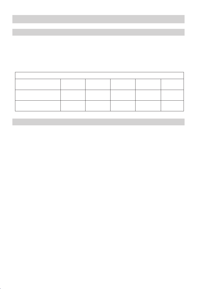
Depending on the specified directives or standards, the level switch NRS 1-50 is intended to be used in
combination with the following level electrodes:
Level electrode NRG 1...-..
Functional safety acces-
sory to IEC 61508 SIL 3
NRG 16-50 NRG 17-50 NRG 19-50 NRG 111-50
Functional safety acces-
sory to VdTÜV Bulletin 100
NRG 16-50
NRG 16-11
NRG 17-50
NRG 17-11
NRG 19-50
NRG 19-11
NRG 111-50
NRG 111-11
NRG 16-36
Marine applications
e. g. DNV LR Directives
NRG 16-50S NRG 16-11S NRG 16-38S NRG 16-39S
Function
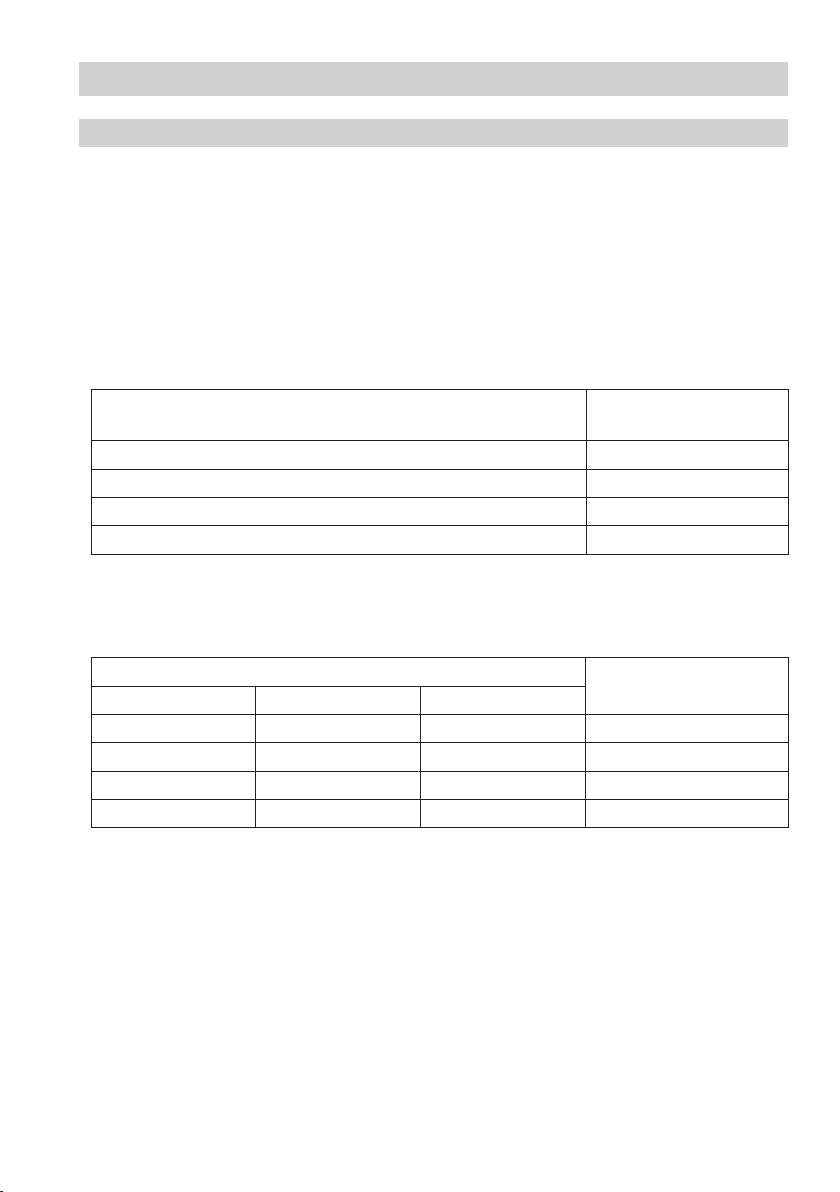
The level switch NRS 1-50 is designed for different electrical conductivities of the boiler water and for
connecting one or two level electrodes.
See section Schematic representations of arrangements.
When the water level falls below the low level the level electrodes are exposed and a low level alarm is
triggered in the level switch. This switchpoint is determined by the length of the electrode rod
(level electrode NRG 1...-50, NRG 1...-11, NRG 16-36).
After the de-energizing delay has elapsed, the two output contacts of the level switch will open the
safety circuit for the heating. The switching-off of the heating is interlocked in the external safety
circuit and can only be deactivated when the level electrode enters the water again.
In addition, two signal outputs for external signalling devices close instantaneously.
An alarm will also be raised if a malfunction occurs in the level electrode and/or the electrical
connection.
If the level electrode is installed in an isolatable level pot outside the boiler, make sure that the
connecting lines are rinsed regularly. During the rinsing process the water level cannot be measured
in the level pot for 5 minutes. The level switch therefore bypasses the level electrode and monitors the
rinsing and bypass time (standby input, controlled by the logic unit SRL 6-50).
If the connecting lines for steam ≥ 40 mm and water ≥ 100 mm, the installation is considered to be
internal. In this case the rinsing processes do not have to be monitored.
An automatic self-testing routine monitors the safety functions in the level switch and the level
electrodes. In the event of a malfunction the safety circuit opens instantaneously and switches the
heating off.
Alarm and errror messages are indicated by LEDs and a signal output for each level electrode is
energized without delay.
An alarm can be simulated by pressing the test button.

5
NRS 1-50 For TWO Electrodes - Installation Instructions - 818953-08
Note
The level electrodes NRG 1...-50, NRG 1...-11 and NRG 16-36 are simple items of electrical
equipment as specified in EN 60079-11 section 5.7. The equipment must be equipped with
approved Zener barriers if used in potentially explosive areas. Applicable in Ex-zones 1, 2
(1999/92/EC).
The equipment does not bear an Ex marking.
Note that the requirements of the IEC 61508 are not met if the NRG 1...-50, NRG 1...-11
and NRG 16-36 + Zener barriers + NRS 1-50 are interconnected!
Important Notes – continued –
Potentially explosive areas
The level switch NRS 1-50 must not be used in potentially explosive areas.
Safety note
Water level limiters are safety devices and must only be installed, wired and commissioned by
qualified and competent staff.
Retrofitting and maintenance work must only be performed by qualified staff who – through adequate
training – have achieved a recognised level of competence. Incorrect installation, wiring or commis-
sioning can endanger the safety of your plant.
Danger
The terminal strips of the equipment are live during operation.
This presents the danger of electric shock!
Always cut off power supply to the equipment before mounting, removing or connecting
the terminal strips!
Attention
The name plate specifies the technical features of the equipment. Note that any piece of
equipment without its specific name plate must neither be commissioned nor operated.
Scope of supply
NRS 1-50
1 Level switch NRS 1-50
1 Installation manual

6NRS 1-50 For TWO Electrodes - Installation Instructions - 818953-08
Functional Safety acc. to IEC 61508
Safety characteristics of the subsystem NRG 1...-50 / NRS 1-50
The level switch NRS 1-50 is certified acc. to IEC 61508 if used in combination with level electrode
NRG 1...-50 / NRG 16-36 .
The combination NRG 1...-50 / NRG 16-36 / NRS 1-50 corresponds to a type B subsystem with Safety
Integrity Level (SIL) 3. Type B means that the behaviour under fault conditions of the used components
cannot be completely determined. The functional safety of the equipment combination refers to the
detection and evaluation of the water level and, as a consequence, the contact position of the output
relays.
The design of the equipment combination NRG 1...-50 / NRG 16-36 / NRS 1-50 corresponds to the
architecture 1oo2.
This architecture consists of two channels that detect and diagnose faults in each other. If a fault is
detected, the equipment combination NRG 1...-50 / NRG 16-36 / NRS 1-50 will go to the safe state,
which means that the contacts of both output relays will open the safety circuit.
Safety characteristics SIL Architecture Lifetime
(a)
Proof Test
Interval (a)
General 3 1oo2 20 20
SFF PFDav PFHav λDU
Level switch NRS 1-50 in conjunction with one
or two level electrode(s)
>90% <5 x 10⁻⁴ <5 x 10⁻⁸ <10 x 10-8 /h
Fig. 1
Terms and abbreviations
Terms
Abbreviations Description
Safety Integrity Level
SIL Classification of the Safety Integrity Level acc. to IEC 61508
Lifetime (a) Functional safety: Lifetime in years
Safe Failure Fraction
SFF
Percentage of failures without the potential to put the safety-related system into a
dangerous state
Probability Failure per
Demand (Low Demand) PFDav
Average probability of failure on demand for low demand mode (once a year)
Probability Failure per Hour
PFHav Probability of failure per hour
λDU
Failure rate for all dangerous undetected failures (per hour) of a channel of a subsystem
Fig. 2

7
NRS 1-50 For TWO Electrodes - Installation Instructions - 818953-08
Functional Safety acc. to IEC 61508 – continued –
Determination of the Safety Integrity Level (SIL) for safety-related systems
Level electrode, level switch and actuators (auxiliary contactor in safety circuit) are subsystems and
together constitute a safety-related system that executes a safety function.
The specification of the safety-related characteristics Fig. 1 refers to the level electrode and the level
switch including the output contacts. The actuator (e. g. an auxiliary contactor in the safety circuit) is
installation specific and, according to IEC 61508, must be considered separately for the whole safety-
related system.
Table Fig. 3 shows the dependence of the Safety Integrity Level (SIL) on the average probability of failure
on demand of a safety function for the whole safety-related system (PFDsys). The“Low demand mode”
is here considered for a water level limiter, which means that the frequency of demands for operation of
the safety-related system is no greater than one per year.
Low demand mode PFDsys Safety Integrity Level
(SIL)
≥ 10 -5 ... < 10 -4 4
≥ 10 -4 ... < 10 -3 3
≥ 10 -3 ... < 10 -2 2
≥ 10 -2 ... < 10 -1 1
Fig. 3
The table in Fig. 4 indicates the attainable Safety Integrity Level (SIL) as a function of the Safe Failure
Fraction (SFF) and the Hardware Fault Tolerance (HFT) for safety-related systems.
Hardware Fault Tolerance (HFT) for type B Safe Failure Fraction
(SFF)
012
SIL 1 SIL 2 < 60 %
SIL 1 SIL 2 SIL 3 60 % - < 90 %
SIL 2 SIL 3 SIL 4 90 % - < 99 %
SIL 3 SIL 4 SIL 4 ≥ 99 %
Fig. 4

8NRS 1-50 For TWO Electrodes - Installation Instructions - 818953-08
NRS 1-50
Supply voltage
24 VDC +/– 20 %, 0.3 A
100-240 VAC + 10/– 15 %, 47-63 Hz, 0.2 A (optional)
External fuse
0.5 A (semi-delay)
Power consumption
7 VA
Response sensitivity (Electrical conductivity of water at 25 °C)
> 0.5 ... < 1000 µS/cm or
> 10 ... < 10000 µS/cm
Electrical connection of level electrode
2 inputs for level electrode NRG 1...-50, NRG 1...-11, NRG 16-36, 4 poles, with screen,
Sensitivity 0.5 μS/cm or 10 μS/cm (at 25 °C).
Stand-by input
2 volt-free inputs, 24 V DC, for monitoring the purging and bypass time.
Max. bypass time: 5 minutes.
Safety circuit
2 volt-free make contacts, 6 A 250 V AC / 30 V DC cos ϕ= 1.
Delay of response: 3 seconds, 15 sec. for marine applications.
Provide inductive loads with RC combinations according to manufacturer's specification to ensure
interference suppression.
Signal output
2 volt-free outputs for instantaneous external signalling, 24 VDC, max. 100 mA (semiconductor output).
Indicators and adjustors
2 buttons for test and diagnosis,
2 red/green LEDs for indicating the operating mode and alarm.
3 red LEDs for diagnosis,
2 two-pole code switches for setting the number of electrodes.
Housing
Housing material: base: polycarbonate, black; front: polycarbonate, grey.
Cross section of connection: 1 x 4.0 mm2solid per wire or
1 x 2.5 mm2 per stranded wire with sleeve to DIN 46228 or
2 x 1.4 mm2per stranded wire with sleeve to DIN 46228; terminal strips can be detached
Fixing of housing: Mounting clip on supporting rail TH 35, EN 60715
Electrical safety
Degree of contamination: 2, overvoltage category III to EN 61010-01.
Protection
Housing: IP 40 to EN 60529
Terminal strip: IP 20 to EN 60529
Weight
approx. 0.5 kg
Technical Data

9
NRS 1-50 For TWO Electrodes - Installation Instructions - 818953-08
NRS 1-50 – continued –
Further conditions:
Ambient temperature
when system is switched on: 0 ° ... 55 °C
during operation: –10 ... 55 °C
Transport temperature
–20 ... +80 °C (<100 hours), defrosting time of the de-energized equipment before it can be put into
operation: 24 hours.
Storage temperature
–20 ... +70 °C, defrosting time of the de-energized equipment before it can be put into operation:
24 hours.
Relative humidity
max. 95 %, no moisture condensation
Site altitude
max. 2000 m
Technical Data – continued –

10 NRS 1-50 For TWO Electrodes - Installation Instructions - 818953-08
Example name plate / marking
Fig. 5
The manufacturing date is shown at the side of the equipment.
$
$
1/=><++1
7ÞXMROXO\=^\!!
",\OWOX
7KNOSX1O\WKXc
1Safety note
2Function
3Type designation
4Power consumption
5Protection
6Operating data
(max. ambient temperature)
7Supply voltage
8Protection class
9Wiring diagram
0Type approval no.
aMaterial number, serial number
bManufacturer
cType approval
dDisposal note
Optional data
eMeasuring range in µS/cm
fMeasuring range in ppm
gRelay protection
hNote on functional safety
iMarking for limiter or monitor
jField for adjusted limit
kOperating principle acc. to EN 60730-1

11
NRS 1-50 For TWO Electrodes - Installation Instructions - 818953-08
Dimensions and Functional Elements
NRS 1-50
1Upper terminal strip
2Lower terminal strip
3Fixing screws (cross recess head screws M3)
4Code switch for switching on/off level electrode 1 / 2
5 Code switch for switching on/off level electrode 1 / 2
6Enclosure
7Supporting rail type TH 35, EN 60715
Key
The code switches are accessible after removing the lower terminal strip. The terminal strips can be
unplugged after undoing the right and the left fixing screws.
123456789101112131415
11
ON ON
22
1
2716 17 18 19 20 21 22 23 24 25 26 28 29 30
Fig. 6
1
2
3
4 5
6
7
100
120
74

12 NRS 1-50 For TWO Electrodes - Installation Instructions - 818953-08
Electrical Connection
Connection of level electrode
Connect the safety circuit for the heating to terminals 23, 24 and 26, 27. Wenn used as water level
limiter according to EN 12952 / EN 12953 connect the output contacts of the two monitoring channels
by adding a wire link between the terminals 24 and 26.
Provide the output contacts with a 2 A or 1 A (for 72 hours operation) slow-blow fuse.
Connection of safety circuit
Installation
Mounting level switch NRS 1-50
The level switch NRS 1-50 is clipped onto the support rail 7type TH 35, EN 60715 in the control
cabinet. Fig. 6
For connecting the level switch with the logic unit use a control cable, e. g. 2 x 0.5 mm2.
The control voltage must not exceed 36 V DC.
Connection of logic unit (standby input)
Note
nIn the event of an alarm the level switch NRS 1-50 does not interlock automatically.
If a lock function is required by the installation it must be provided in the follow-up
circuitry (safety circuit). The circuitry must meet the requirements of the EN 50156.
Supply voltage
Provide the level switch NRS 1-50 with an external semi-delay fuse 0.5 A.
To connect the level electrodes please use:
nFor level switch NRS 1-50 with response sensitivity 10 μS:
Screened multi-core control cable, min. conductor size 0.5 mm2, e.g. LiYCY 4 x 0.5 mm2,
max. length 100 m.
nFor level switch NRS 1-50 with response sensitivity 0.5 μS:
Double-screened multi-core low-capacitance data cable, min. conductor size 0.5 mm2,
Li2YCY PiMF 2 x 2 x 0.5 mm2, max. length 30 m.
Wire terminal strip in accordance with the wiring diagram. Fig. 7. Connect screens to terminals 5 and
13 and to the central earthing point (CEP) in the control cabinet.

13
NRS 1-50 For TWO Electrodes - Installation Instructions - 818953-08
A signal output for the connection of further external signalling equipment is allocated to each
monitoring channel in the level switch, max. load 100 mA. For connecting the level switch with the
logic unit use a control cable, 2 x 0.5 mm2. In the event of an alarm or error message the signal
outputs (terminals 20, 21 and 29, 30) open instantaneously.
Connection for signal output
Electrical Connection – continued –
Tools
nScrewdriver for slotted screws, size 3.5 x 100 mm, completely insulated.
Danger
nFor the supply of the level switch NRS 1-50 with 24 V DC use a safety extra-low
voltage (SELV) power supply unit that must be electrically isolated from dangerous
contact voltages and must meet at least the requirements on double or reinforced
isolation acc. to EN 61010-1, EN 60730-1, EN 60950-1 or EN 62368-1
(safe isolation).
nAny item of equipment that you want to connect to terminals 6, 7, 14, 15 (standby
input 1 / 2) must be certified to have at least double or reinforced isolation according
to EN 61010-1, EN 60730-1, EN 60950-1 or EN 62368-1 (safe isolation) between the
standby inputs and the live parts of the installation that are not supplied with safety
extra-low voltage (SELV).
Attention
nProvide the level switch NRS 1-50 with an external semi-delay fuse 0.5 A.
nConnect screens to terminals 5 and 13 and to the central earthing point (CEP) in the
control cabinet.
nTo protect the switching contacts provide the safety circuit with a slow-blow fuse 2 A
or 1.0 A (for 72 hrs. operation).
nWhen switching off inductive loads, voltage spikes are produced that may impair
the operation of control and measuring systems. Connected inductive loads must be
provided with suppressors such as RC combinations as specified by the manufacturer.
nWhen used as water level limiter according to EN 12952 / EN 12953 connect termi-
nals 24 and 26 by adding a wire link.
nInstall connecting lines to level electrodes and logic unit separated from power cables.
nDo not use unused terminals as support point terminals.

14 NRS 1-50 For TWO Electrodes - Installation Instructions - 818953-08
2716
12345678
17 18 19 20 21 22 23 24
9
25
10
26
11 12
28
13
29
14
30
15
11
22
33
++-
L
M 0,5A
(+)(-)
-
N
Test Test
** +
+-
-
Fig. 7
+ – + –
L N
(+) (–)
8
909
a
0
bb
c c
– + – +
c
NRG 16-36
21
4
3
NRG 1..-50
NRG 1..-11
NRG 1..-50
NRG 1..-11
Electrical Connection – continued –
Wiring diagram for level switch NRS 1-50
8Supply voltage
9Signal output 1 / 2 for external alarm 24 V DC, 100 mA (semiconductor output)
0Safety circuit, input and output
aWire link, on site, when used as water level limiter acc. to EN 12952 / EN 12953
b Stand-by input 1 / 2, 24 V DC, for connecting the logic unit SRL 6-50
cLevel electrode NRG 1...-50, NRG 1...-11 or NRG 16-36
CEP Central earthing point in control cabinet
Key
CEP CEP
* NRS 1-50 with response sensitivity 0.5
μ
S:
Connect the two internal screens to terminal 5/13
and to the CEP.

15
NRS 1-50 For TWO Electrodes - Installation Instructions - 818953-08
dd
e
ef f
d d
e
f
e
f
dd
geff
Fig. 8 Fig. 9
Fig. 10 Fig. 11
Fig. 12 Fig. 13
Electrical Connection – continued –
Schematic representations of arrangements
ee
dLevel electrode(s) NRG 1...-50
eLevel switch NRS 1-50
Key
fSafety circuit
gLevel switch NRS 1-50 for low-level pre-alarm

16 NRS 1-50 For TWO Electrodes - Installation Instructions - 818953-08
Electrical Connection – continued –
Explanatory notes to schematic respresentations
Steam boiler plants according to EN 12952-07 / EN 12953-06, 72 h operation
Fig. 8
Combination consisting of 2 level electrodes NRG 1...-50 and 1 level switch NRS 1-50 as water level
limiter. Functional safety IEC 61508, SIL 3.
The equipment combination meets the demand for two independent water level limiters.
(Pressurized) hot-water plants and electrically heated steam boilers according to EN 12953-06
Steam boiler plants with high availability according to EN 12952-07 / EN 12953-06, 72h
operation
Fig. 9
Combination consisting of 1 level electrode NRG 1...-50 and 1 level switch NRS 1-50 as water level
limiter. Functional safety IEC 61508, SIL 3.
Hot water installations require two independent and separate water level limiters. For this purpose
one equipment combination NRG 1...-50/NRS 1-50 shall be installed in the hot-water boiler and the
second one in the pressure maintaining vessel, the expansion tank or the like (depending on the type
of pressurization). For electrically heated steam boilers one water level limiter is sufficient.
To meet the plant operator's demand for a higher level of availability of the steam boiler plant, two
(or three) independent equipment combinations NRG 1...-50/NRS 1-50 can be installed in the steam
boiler.
Further applications in accordance with national sets of regulations
Fig. 10
Combination consisting of 1 level electrode NRG 1...-50 and 1 level switch NRS 1-50 as
water level limiter.
The level switch opens two separate safety circuits. Functional safety IEC 61508, SIL 3.
Fig. 11
Combination consisting of 2 level electrodes NRG 1...-50 and 1 level switch NRS 1-50 as
water level limiter.
The level switch opens two separate safety circuits. Functional safety IEC 61508, SIL 3.
Fig. 12
Combination consisting of 1 level electrode NRG 1...-50 and 1 level switch NRS 1-50 as
water level limiter and 1 level electrode NRG 1...-50 / 1 level switch NRS 1-50 as first low-level alarm.
Functional safety IEC 61508, SIL 3.
Fig. 13
Combination consisting of 2 level electrodes NRG 1...-50 and 2 level switches NRS 1-50 as
water level limiter.
The level switch opens two separate safety circuits. Functional safety IEC 61508, SIL 3.
Note
nPlease observe the safety-related characteristics on page 7, Fig. 1.

17
NRS 1-50 For TWO Electrodes - Installation Instructions - 818953-08
Commissioning Procedure
Changing configuration
Danger
The terminal strips of the NRS 1-50 are live during operation.
This presents the danger of electric shock!
Always cut off power supply to the equipment before mounting, removing or connecting
the terminal strips!
Basic Settings
Factory setting
Level Switch NRS 1-50
The level switch features the following factory set default values:
nDe-energizing delay: 3 sec., 15 sec. for marine applications.
nConfiguration: Operation with two level electordes NRG 1 ...-50. S1/S2 of code switches 4and 5
set to OFF.
Note
nIf only one level electrode is switched on, only the LEDs for power and alarm of the
corresponding channels will be illuminated.
If only one electrode is used for operation (e. g. in case of emergency operation) change the settings as
follows:
nSwitch off mains voltage.
nUnscrew the right and left fixing screws 3and remove the lower terminal strip 2, Fig. 6
n Depending on which electrode shall be deactivated, set S1/S2 of code switches 4and 5to ON.
nAttach lower terminal strip and fasten fixing screws.
nApply mains voltage, equipment is re-started.
Code switch 4Code switch 5
S 1 S 2 S 1 S 2
Level electrode 1 activated OFF OFF
Level electrode 1 deactivated ON ON
Level electrode 2 activated OFF OFF
Level electrode 2 deactivated ON ON
4
Toggle switch, white
5
Toggle switch, white

18 NRS 1-50 For TWO Electrodes - Installation Instructions - 818953-08
Commissioning – continued –
Checking switchpoint and function
Start
Activity Indication Function
Apply
mains voltage.
All LEDs are illuminated.
System is being started and tested,
this takes approx. 10 sec.
Output contacts are open.
Signal outputs 1 and 2 are closed.
All LEDs are illuminated for
more than 10 sec.
System malfunction. Possible causes:
Faulty power supply, level switch defective.
Raise water in boiler until the
switchpoint “low water level (LW)”
is ecxeeded. Level electrode(s)
make(s) contact with the water.
Green LEDs for level
electrode 1 / 2 illuminated.
Output contacts are closed.
Signal outputs 1 and 2 open.
Checking switchpoint and function
Lower water level until it is below
the switchpoint “low water level
(LW)”. Level electrode(s) is/are
exposed.
Red LEDs
for level electrode 1 / 2 are
flashing.
De-energizing delay is running.
Signal outputs 1 and 2 are closed
instantaneously.
Red LEDs
for level electrode 1 / 2
illuminated.
Delay time has elapsed,
output contacts open.
Signal outputs 1 and 2 are closed.
Possible installation faults
Status and indication Fault Remedy
Sightglass indicates level
below switchtpoint “low water
(LW)”, red LEDs for level
electrodes 1/2 not illuminated.
Safety circuit closed.
Electrode rod(s) is/are too long. Cut electrode rod(s) to the length dictated by the
switchpoint LW.
If installed inside the boiler: Up-
per vent hole in protection tube
does not exist or is obstructed.
Check installation of level electrode. Make sure
that the level in the protection tube corresponds
to the actual water level.
Water level sufficient. Red
LEDs for level electrodes 1 / 2
illuminated! Safety circuit open.
Electrode rod(s) is/are too short. Replace electrode rod(s) and cut new rods to
the length dictated by the switchpoint LW.
The earth connection to the
vessel is interrupted.
Clean seating surfaces and screw in level
electrode with metallic joint ring. Do not insulate
the electrode with hemp or PTFE tape!
Electrical conductivity of the
boiler water too low.
Set response sensitivity of the level switch to
0.5 μS/cm.
Upper vent hole flooded.
Check installation of level electrode. Make sure
that the level in the protection tube corresponds
to the actual water level.
LED alarm 2 /
operating mode
Level electrode1
Test & diagnosis
button
LED alarm 1 /
operating mode
Level electrode 2
Test & diagnosis
button
Diagnosis LED
Fig. 14

19
NRS 1-50 For TWO Electrodes - Installation Instructions - 818953-08
Operation
Activity Indication Function
Level electrode(s) submerged. Green LEDs for level
electrode 1 / 2 illuminated.
Output contacts are closed.
Signal outputs 1 / 2 open.
Alarm
Level electrode(s) exposed,
level below low water level
(LW).
Red LEDs
for level electrode 1 / 2 are
flashing.
De-energizing delay is running.
Signal outputs 1 / 2 are closed instantaneously.
Red LEDs
for level electrode 1 / 2
illuminated.
Delay time has elapsed, output contacts open.
Signal outputs 1 / 2 are closed.
Test channel 1 and 2
During operation:
Press key 1 or 2 and hold it
down until the end of the test,
level switch must react as if
there was an alarm.
Red LEDs
for level electrode 1 / 2 are
flashing.
Alarm simulated in channel 1 or 2.
De-energizing delay is running.
Signal outputs 1 / 2 are closed instantaneously.
Red LEDs
for level electrode 1 / 2
illuminated.
Delay time has elapsed, output contacts open.
Signal outputs 1 / 2 are closed.
Test finished.
Operation, Alarm and Test
Indicators and adjustors
Attention
Before carrying out the fault diagnosis please check:
Supply voltage:
Is the level switch supplied with the voltage specified on the name plate?
Wiring:
Is the wiring in accordance with the wiring diagram and the relevant schematic
representation of arrangement?
Configuration:
Are the code switch settings
4and 5
correct for the number of level
electrodes used?
Troubleshooting
Indication, diagnosis and remedy
LED alarm 2 /
operating mode
Level electrode1
Test & diagnosis
button
LED alarm 1 /
operating mode
Level electrode 2
Test & diagnosis
button
Diagnosis LED
Fig. 14

20 NRS 1-50 For TWO Electrodes - Installation Instructions - 818953-08
Fault Indication and Troubleshooting – continued –
Diagnosis
Display 1 and activity Display 2 Fault Remedy
LED alarm 1 and
diagnosis LED 1
illuminated. Press and hold
down key 1.
Diagnosis
LED 1
flashing.
Malfunction in level electrode 1,
malfunction in level switch,
faulty wiring,
faulty measuring voltage.
– check wiring,
– measure electrode voltages,
– clean and, if necessary, exchange
– level electrode,
– exchange level switch.
Diagnosis
LED 2
flashing.
Malfunction in level electrode 1,
malfunction in level switch,
faulty wiring.
Diagnosis
LED 3
flashing.
Interference voltage causing
malfunction, boiler earth without
PE
Provide screen and earthing,
connect boiler with PE.
LED alarm 2 and
Diagnosis LED 2
illuminated. Press and hold
down key 2
Diagnosis
LED 1
flashing.
Malfunction in level electrode 2,
malfunction in level switch,
faulty wiring,
faulty measuring voltage.
– check wiring,
– measure electrode voltages,
– clean and, if necessary, exchange
– level electrode,
– exchange level switch.
Diagnosis
LED 2
flashing.
Malfunction in level electrode 2,
malfunction in level switch,
faulty wiring.
Diagnosis
LED 3
flashing.
Interference voltage causing
malfunction, boiler earth without
PE.
Provide screen and earthing,
connect boiler with PE.
LED alarm 1 and 2
and Diagnosis LED 3
illuminated. Press and hold
down key 1 or 2.
Diagnosis
LED 1
flashing.
Malfunction in processor, stand-
by fault.
Observe operating instructions for
the logic unit SRL. Replace level
switch.
Diagnosis
LED 2
flashing.
Internal voltage fault.
Replace level switch.
Diagnosis
LED 3
flashing.
Malfunction in relay.
Once the fault is eliminated, the level switch returns to normal operation.
After elimination of the fault switch off the mains voltage and switch it on again after approx. 5 sec.
Fault indication
Status Diagnosis Function Next activity
Faulty evaluation of level
electrode 1, channel 1
Diagnosis LED 1 and
LED alarm 1 illuminated.
Output contacts are opened
instantaneously.
Signal output 1 closes
instantaneously.
next:
Press key 1.
Faulty evaluation of level
electrode 2, channel 2
Diagnosis LED 2 and
LED alarm 2 illuminated.
Output contacts are opened
instantaneously.
Signal output 2 closes
instantaneously.
next:
Press key 2.
Malfunction in level switch
detected.
Diagnosis LED 3 and
LED alarm 1 and 2
illuminated.
Output contacts are opened
instantaneously.
Signal outputs 1 and 2 are closed
instantaneously.
next:
Press key 1 or
key 2.
Indication, diagnosis and remedy – continued –
Other manuals for NRS 1-50
3
Table of contents
Other GESTRA Switch manuals

GESTRA
GESTRA NRS 2-50 User manual

GESTRA
GESTRA NRS 2-50 User manual

GESTRA
GESTRA NRS 2-4 User manual

GESTRA
GESTRA NRS 1-2 User manual

GESTRA
GESTRA NRS 1-50 User manual

GESTRA
GESTRA TRS 5-8 User manual

GESTRA
GESTRA NRS 1-56 User manual

GESTRA
GESTRA LRS 1-7 Manual

GESTRA
GESTRA NRS 2-1 Quick guide

GESTRA
GESTRA NRS 1-56 User manual

GESTRA
GESTRA NRS 1-8 User manual

GESTRA
GESTRA NRS 1-52 User manual

GESTRA
GESTRA NRS 1-51 User manual

GESTRA
GESTRA LRS 1-50 User manual

GESTRA
GESTRA TRS 5-52 User manual

GESTRA
GESTRA NRS 2-40 User manual

GESTRA
GESTRA NRGS 15-1 User manual

GESTRA
GESTRA LRGS 15-1 User manual

GESTRA
GESTRA TRS 5-6 User manual

GESTRA
GESTRA NRGS 15-1 User manual