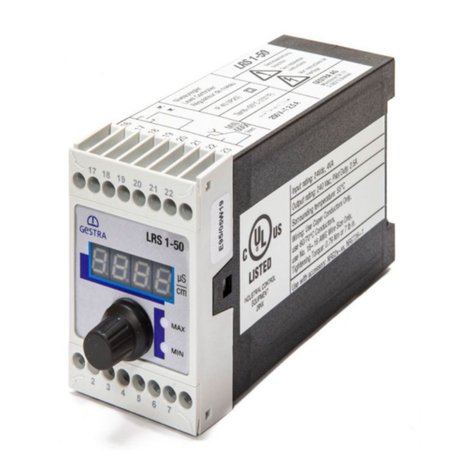
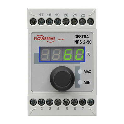
GESTRA NRS 1-56 User manual

Original Installation &
Operating Manual
Level Switch
NRS 1-56
850697-00-00
EN (USA)
English

2NRS 1-56 - USA - Installation & Operating Manual - 850697-00
Contents
Content of this Manual........................................................................................................................ 4
Scope of supply, product package...................................................................................................... 4
How to use this Manual....................................................................................................................... 5
Illustrations and symbols used........................................................................................................... 5
Hazard symbols in this Manual........................................................................................................... 5
Types of warning ................................................................................................................................. 6
Specialist terms, abbreviations .......................................................................................................... 7
Usage for the intended purpose.......................................................................................................... 8
Applicable directives and standards................................................................................................ 9
Improper use ....................................................................................................................................... 9
Basic safety information ..................................................................................................................... 9
Required personnel qualifications.................................................................................................... 10
Notes on product liability.................................................................................................................. 10
Function ............................................................................................................................................. 10
Technical data ................................................................................................................................... 11
Rating plate, identification NRS 1-56 ............................................................................................... 13
Default factory settings..................................................................................................................... 14
Functional elements and dimensions............................................................................................... 15
Installing the NRS 1-56 level switch................................................................................................. 16
Safety information on the electrical connection.............................................................................. 16
Wiring diagram for the NRS 1-56 level switch................................................................................. 17
Electrical connection......................................................................................................................... 18
Connecting the 24V DC power supply .......................................................................................... 18
Connecting the output contacts..................................................................................................... 18
Connecting the level electrodes .................................................................................................... 18
Connection examples ........................................................................................................................ 19
Fill control - connection of various level electrodes ....................................................................... 19
Discharge control - connection of various level electrodes ............................................................ 20
Changing the equipment settings..................................................................................................... 21
Changing the sensitivity and function............................................................................................ 21
Configuring function and sensitivity .............................................................................................. 22
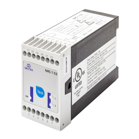
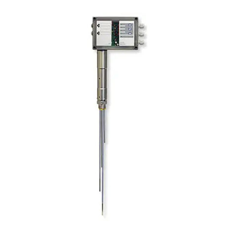
3NRS 1-56 - USA - Installation & Operating Manual - 850697-00
Contents
Bringing into service - starting, checking switchpoints and function............................................ 23
Bringing into service - operation, testing......................................................................................... 25
System malfunctions......................................................................................................................... 27
Causes ......................................................................................................................................... 27
Indication of system malfunctions................................................................................................. 28
Action against high-frequency interference................................................................................... 28
What to do in the event of system malfunctions.............................................................................. 29
Taking out of service......................................................................................................................... 29
Disposal ............................................................................................................................................. 29
UL components.................................................................................................................................. 29

4NRS 1-56 - USA - Installation & Operating Manual - 850697-00
Content of this Manual
Product:
Level Switch NRS 1-56
First edition:
IOM 850697-00/08-2021cm
You can find the latest Installation & Operating Manuals on our website:
http://www.gestra.com
© Copyright
All rights reserved. Any misuse, particularly reproduction and dissemination to third parties, is not
permitted. The General Terms & Conditions of GESTRA AG apply.
Scope of supply, product package
■ 1 x level switch NRS 1-56
■ 1 x Installation & Operating Manual

5NRS 1-56 - USA - Installation & Operating Manual - 850697-00
How to use this Manual
This Installation & Operating Manual describes the correct use of the NRS 1-56 level switch. It
applies to persons who integrate this equipment in control systems, install, bring into service,
operate, maintain and dispose of this equipment. Anyone carrying out the above-mentioned
activities must have read this Installation & Operating Manual and understood its contents.
■ Read this Manual in full and follow all instructions.
■ Please also read the instructions for use of any accessories.
■ The Installation & Operating Manual is part of the product package. Keep it in an easily
accessible location.
Availability of this Installation & Operating Manual
■ Make sure this Installation & Operating Manual is always available to the operator.
■ If you pass on or sell the equipment to a third party, please also hand over the Installation &
Operating Manual.
Hazard symbols in this Manual
Danger zone, dangerous situation
Danger of death from electric shock
Illustrations and symbols used
1. Action to be taken
2.
■ Lists
◆ Bullet points in lists
A Keys to illustrations
Additional
information
Read the relevant
Installation & Operating Manual

6NRS 1-56 - USA - Installation & Operating Manual - 850697-00
Types of warning
DANGERDANGER
Warning of a dangerous situation that results in death or serious injury.
WARNING
Warning of a dangerous situation that may possibly result in death or serious injury.
CAUTIONCAUTION
Warning of a situation that may result in minor or moderate injury.
ATTENTIONATTENTION
Warning of a situation that results in damage to property or the environment.

7NRS 1-56 - USA - Installation & Operating Manual - 850697-00
Specialist terms, abbreviations
Here, we explain some abbreviations, specialist terms, etc., which are used in this Manual.
NRG .. / NRS ..
GESTRA equipment and type designations, see page 8.
SELV
Safety Extra Low Voltage

8NRS 1-56 - USA - Installation & Operating Manual - 850697-00
Usage for the intended purpose
The NRS 1-56 level switch can be used in conjunction with various conductive level electrodes as
an on/off level control system in steam boilers and hot water installations and in condensate and
feedwater tanks. The NRS 1-56 is classified as operating control in accordance with UL60730-1.
The NRS 1-56 level switch also indicates two alarm states, which can be configured as MIN and
MAX.
Overview of possible equipment combinations
Level switch Level electrode Version
NRS 1-56 NRG 1.-52 4-rod electrode
To ensure proper use in all applications, please also read the Installation & Operating
Manuals for the system components used.
■ You will find the latest Installation & Operating Manuals for the system components
listed in the table above on our website:
http://www.gestra.com

9NRS 1-56 - USA - Installation & Operating Manual - 850697-00
Usage for the intended purpose
Applicable directives and standards
The NRS 1-56 level switch has been tested and approved for use in the scope governed by the
following directives and standards:
Standards:
■ UL 60730-1 and CAN/CSA E60730-1
General Requirements for Automatic Electrical Controls
■ UL 60730-2-15 and CAN/CSA E60730-2-15
Requirements for Automatic Electrical Water Level Sensing Controls
Improper use
There is a danger of death due to explosion if the equipment is used in potentially
explosive atmospheres.
Do not use the equipment in potentially explosive atmospheres.
Do not bring any equipment into service that does not have its own specific rating
plate.
The rating plate indicates the technical features of the equipment.

10 NRS 1-56 - USA - Installation & Operating Manual - 850697-00
Basic safety information
There is a risk of electric shock during work on electrical systems.
■ Always switch off the voltage to the equipment before performing work on the
terminal strips.
■ Check that the plant is not carrying live voltage before commencing work.
Faulty equipment is a danger to plant safety.
■ If the NRS 1-56 level switch does not behave as described on page 23, it may be
faulty.
■ Perform failure analysis.
■ Only replace faulty equipment with identical equipment from GESTRA AG.
Required personnel qualifications
Activity Personnel
Integration in control system Specialist staff Plant designer
Installation/electrical connection/
bringing into service Specialist staff Electrician/installer
Operation Boiler service technician Staff trained by the plant operator
Maintenance work Specialist staff Electrician
Setup work Specialist staff Plant construction
Notes on product liability
The manufacturer cannot accept any liability for damages resulting from improper use of the
equipment.

11NRS 1-56 - USA - Installation & Operating Manual - 850697-00
Function
The NRS 1-56 level switch uses the conductivity of the water to measure the level.
The level switch is designed for different conductivities and for connection to a four tipped probe.
The level switch functions as an on/off level control system (fill/discharge, switchable), and also
indicates when the water reaches two independent alarm states, which can be configured as
MIN or MAX.
The switchpoints for water level control and for the MIN or MAX levels are determined by the length
of the respective electrode rods.
For water level control, the level switch recognizes whether the electrode rods are immersed or
exposed and, depending on which function is set, it switches the controller output contact, which
then turns the feedwater pump on or off, for example. The Pump LED lights up when the level
switch has switched the feedwater pump on, for example.
Behavior in the event of MIN/MAX water level alarms
When the MIN or MAX water level is reached, the level switch recognizes that the corresponding
electrode rod is immersed or exposed. When the off delay has elapsed, the relevant Alarm 1/Alarm 2
output contact is switched. The Alarm 1/Alarm 2 LED simultaneously lights up red.
Alarm simulation
Press the button to begin a test sequence. During the test sequence, the MIN and/or
MAX alarm is simulated, see table on page 26.
Behavior in the event of fault indications
If faults occur in the level electrode and/or the electrical connection, the integrated relays are
de-energized.
Alarm and fault indications are displayed by LEDs, see page 28.

12 NRS 1-56 - USA - Installation & Operating Manual - 850697-00
Technical data
Supply voltage
■ 24 V DC +/-20 %; SELV / PELV / CLASS2
Power consumption
■ Max. 2 W
Current input
■ Max. 0.2 A
Required external fuse
■ M0.5A (medium time-lag)
Inputs for connecting level electrodes
■ 4 x inputs for level electrodes: NRG 10-52, NRG 16-52 four-pole with shield
Electrode voltage
■ 5 Vss
Response sensitivity [electrical conductivity of water at 77°F (25°C)]
■ > 5 ppm (10 µS/cm) < 5000 ppm (10,000 µS/cm)
Alarm 1/Alarm 2 outputs
■ 2 x volt-free relay contacts, (changeover relays), contact material AgNi0.15, AgSnO2
■ Maximum switching current - 8 A at 250 V AC / 30 V DC - cos ϕ = 1
■ Inductive loads must have interference suppression (RC combination) in accordance with the
manufacturer's specification
Off delay of Alarm 1/Alarm 2 outputs
■ Factory default setting 3 seconds.
Pump output
■ 1 x volt-free relay contact, contact material AgNi0.15, AgSnO2
■ Maximum switching current - 8 A at 250 V AC / 30 V DC - cos ϕ = 1
■ Inductive loads must have interference suppression (RC combination) in accordance with the
manufacturer's specification
Required external fuse for output contacts
■ T2.5A (slow blow)

13NRS 1-56 - USA - Installation & Operating Manual - 850697-00
Technical data
Indicators and controls
■ 1 x button for initiating the test function
■ 1 x multicolor “ON” LED (green/red) - for indicating the operating state and internal errors
◆ green = running
◆ red = power up, malfunction or internal error
■ 1 x red “Alarm 1” LED for indicating a MIN/MAX alarm
■ 1 x red “Alarm 2” LED for indicating a MIN/MAX alarm
■ 1 x green “Pump” LED for indicating pump status ON/OFF
■ 1 x 4-pole code switch for setting function and sensitivity
Protection
■ Terminal box: IP 40 according to EN 60529
■ Terminal strips: IP 20 according to EN 60529
■ As a UL open type, the level switch must be installed in a control cabinet.
Electrical safety
■ Pollution degree 2, overvoltage category II according to UL 60730-1
Admissible ambient conditions
■ Service temperature 32° - 131°F (0° - 55°C)
[at power-on 32° - 131°F (0° - 55°C)]
■ Storage temperature -4° - 158°F (-20° - 70°C) *
■ Transport temperature -4° - 176°F (-20° - 80°C) (< 100 hours) *
■ Air humidity max. 95 %, non-condensing
* Only switch on after a 24-hour defrosting period
Terminal box
■ Terminal box material: Lower section of black polycarbonate (glass-fiber reinforced), front of
gray polycarbonate
■ 2 x 8-pole terminal strips, removable separately
■ Max. wire size per screw terminal:
◆ 1 x AWG12 (4.0mm2) solid, or
◆ 1 x AWG14 (2.5mm2) stranded with sleeve, or
◆ 2 x AWG16 (1.5mm2) stranded with sleeve
■ Terminal box attachment: Mounting clip on support rail TH 35 (according to EN 60715)
Weight
■ Approx. 0.44 lb (0.2 kg)

14 NRS 1-56 - USA - Installation & Operating Manual - 850697-00
19
20
16
17 Alarm2
Alarm1
18
21
22
23
See installation
instructions
Betriebsanleitung
beachten
Voir instructions de
montage
NRS 1-56
Pump/
Valve
Niveauschalter
Level switch
Commutateur de niveau
3s
3s
IP (IP20)40
GESTRA AG
Münchener Str.77
28215 Bremen
Made in Germany
250V ~ T2.5A
Tamb = 55°C)T131°F (
M0.5A
2W
+
_
1
2
3
4
5
6
7
8
Alarm 2
Alarm 1
Pump 2
NRG 1.-..
Pump 1
24V
±20%
Input rating: 24VDC, 2W
Ambient temperature: 32-131°F (0-55°C)
Wiring: Use Copper Conductors Only,
Use 60/75°C Conductors,
Use No.18 16 AWG Wire Size Only,
Tightening: Torque 0.79Nm or 7lb in.
-
Use with accessory: NRG 10-52, NRG 16-52
OPERATING CONTROL
E513189
Output rating : Pilot duty B300 / R300
NRS 1-56 24VDC
19
20
16
17
Alarm2
Alarm1
18
21
22
23
See installation
instructions
Betriebsanleitung
beachten
Voir instructions de
montage
NRS 1-56
Pump/
Valve
Niveauschalter
Level switch
Commutateur de niveau
3s
3s
IP (IP20)40
GESTRA AG
Münchener Str.77
28215 Bremen
Made in Germany
250V ~ T2.5A
Tamb = 55°C)T131°F (
M0.5A
2W
+
_
1
2
3
4
5
6
7
8
Alarm 2
Alarm 1
Pump 2
NRG 1.-..
Pump 1
24V
±20%
Input rating: 24VDC, 2W
Ambient temperature: 32-131°F (0-55°C)
Wiring: Use Copper Conductors Only,
Use 60/75°C Conductors,
Use No.18 16 AWG Wire Size Only,
Tightening: Torque 0.79Nm or 7lb in.
-
Use with accessory: NRG 10-52, NRG 16-52
OPERATING CONTROL
E513189
Output rating : Pilot duty B300 / R300
NRS 1-56 24VDC
19
20
16
17 Alarm2
Alarm1
18
21
22
23
See installation
instructions
Betriebsanleitung
beachten
Voir instructions de
montage
NRS 1-56
Pump/
Valve
Niveauschalter
Level switch
Commutateur de niveau
3s
3s
IP (IP20)40
GESTRA AG
Münchener Str.77
28215 Bremen
Made in Germany
250V ~ T2.5A
Tamb = 55°C)T131°F (
M0.5A
2W
+
_
1
2
3
4
5
6
7
8
Alarm 2
Alarm 1
Pump 2
NRG 1.-..
Pump 1
24V
±20%
Input rating: 24VDC, 2W
Ambient temperature: 32-131°F (0-55°C)
Wiring: Use Copper Conductors Only,
Use 60/75°C Conductors,
Use No.18 16 AWG Wire Size Only,
Tightening: Torque 0.79Nm or 7lb in.
-
Use with accessory: NRG 10-52, NRG 16-52
OPERATING CONTROL
E513189
Output rating : Pilot duty B300 / R300
NRS 1-56 24VDC
Equipment
designation
Mains voltage/
power con-
sumption/
required
external fuse
Rating plate, identification NRS 1-56
Fig. 1
Default factory settings
The NRS 1-56 level switch is delivered with the following factory default settings:
■ Function: Fill control
■ Sensitivity: > 5 ppm (10µS/cm) at 77°F (25°C)
■ Code switch setting: Sliding switch, white (1 = OFF / 2 = ON / 3 = OFF / 4 = OFF)
Configuring function and sensitivity
see page 22, Fig. 9.
Safety
information
Manufacturer
Protection/protection class
Admissible ambient temperature
Inputs
wiring diagram
Serial number
CE marking Disposal
information
The date of production is printed on the side of the equipment.
External fuse for output
contacts
Outputs wiring
diagram

15NRS 1-56 - USA - Installation & Operating Manual - 850697-00
A Upper terminal strip
B Front membrane with LED, see page 23
C Lower terminal strip
D 4-pole code switch, for setting function and
sensitivity
E Terminal box
F Support rail TH 35
Functional elements and dimensions
1
ON 234
567234
19 20 21 2217 18
A
B
C
F
E
The code switch can be accessed by
removing the lower terminal strip.
Equipment settings,
see page 22.
Fig. 2
1
ON 234
D
1.81 in (46 mm)
2.91 in (74 mm)
4.72 in (120 mm)

16 NRS 1-56 - USA - Installation & Operating Manual - 850697-00
Installing the NRS 1-56 level switch
The NRS 1-56 level switch snaps onto a TH 35 support rail in a control cabinet.
DANGERDANGER
There is a risk of electric shock during work on electrical systems.
■ Switch off the voltage to the plant before you install the equipment.
■ Check that the plant is not carrying live voltage before commencing work.
1. Switch off the voltage to the plant and secure any surrounding equipment in the control cabinet
that is live, so it cannot be touched.
2. Carefully press the unit onto the support rail until the holder clips into place.
Safety information on the electrical connection
DANGERDANGER
Incorrectly connecting the level switch or any associated components is a danger
to plant safety.
■ Connect the level switch and all associated components as shown in the
wiring diagram in Fig. 3 of this Manual.
■ Do not use unused terminals as jumpers or support terminals.

17NRS 1-56 - USA - Installation & Operating Manual - 850697-00
Wiring diagram for the NRS 1-56 level switch
Supply voltage
Fuse provided by customer
M0.5A (medium time-lag)
Pump 1 electrode rod
(pump OFF for fill control)
Alarm 1 (MIN/MAX) electrode rodAlarm 2 (MIN/MAX) electrode rod
Fig. 3
17 18 19 20 21 22
234567
ZEP
24 V DC
–
+
M 0,5 A
Relay output
Alarm 2
Pump
output
contact Alarm 1
MIN/MAX MIN/MAXON/OFF
3 s 3 s
Pump 2 electrode rod
(pump ON for fill control)
Functional ground
Tank or reference electrode
CGP

18 NRS 1-56 - USA - Installation & Operating Manual - 850697-00
Electrical connection
Connecting the 24V DC power supply
■ The NRS 1-56 level switch is supplied with 24V DC.
■ A safety power supply unit that delivers a Safety Extra Low Voltage (SELV / PELV / CLASS2)
must be used to supply the equipment with 24V DC.
■ Use a 0.5A medium time-lag fuse as an external fuse.
Connecting the output contacts
■ Connect the outputs as shown in the wiring diagrams in Fig. 3.
■ Only use the terminals specified in the wiring diagrams.
■ Use a 2.5A slow blow fuse to protect the switching contacts.
Connecting the level electrodes
■ Use a shielded, multi-core TC-ER control cable with minimum wire size AWG 18,
e.g., OELFLEX CONTROL TM CY 5G1.
■ Maximum cable length = 328.1ft (100m).
■ Route connecting cables separately from power cables.

19NRS 1-56 - USA - Installation & Operating Manual - 850697-00
Connection examples
Fill control - connection of various level electrodes
Function Code switch setting
MIN/MAX alarm and pump (ON/OFF) / sensitivity [> 5 ppm(10 µS/cm)]
12345678
NRG 1.-52
43
21
Fig. 4
MIN1/MIN2 alarm and pump (ON/OFF) / sensitivity [> 5 ppm(10 µS/cm)]
12345678
NRG 1.-52
43
21
Fig. 5
MAX (Alarm 1)
Pump OFF
Pump ON
MIN (Alarm 2)
Pump OFF
Pump ON
MIN 1 (Alarm 1)
MIN 2 (Alarm 2)

20 NRS 1-56 - USA - Installation & Operating Manual - 850697-00
Connection examples
Discharge control - connection of various level electrodes
Function Code switch setting
MIN/MAX alarm and pump (ON/OFF) / sensitivity [> 5 ppm(10 µS/cm)]
12345678
NRG 1.-52
43
21
Fig. 6
MAX1/MAX2 alarm and pump (ON/OFF) / sensitivity [> 5 ppm(10 µS/cm)]
12345678
NRG 1.-52
43
21
Fig. 7
MAX (Alarm 1)
Pump ON
Pump OFF
MIN (Alarm 2)
MAX 2 (Alarm 1)
MAX 1 (Alarm 2)
Pump ON
Pump OFF
Other manuals for NRS 1-56
1
Table of contents
Other GESTRA Switch manuals

GESTRA
GESTRA NRS 2-4 User manual

GESTRA
GESTRA LRS 1-50 User manual

GESTRA
GESTRA NRS 1-51 User manual

GESTRA
GESTRA TRS 5-52 User manual

GESTRA
GESTRA TRS 5-52 User manual

GESTRA
GESTRA TRS 5-50 User manual

GESTRA
GESTRA NRS 2-40 User manual

GESTRA
GESTRA URS 2 User manual

GESTRA
GESTRA NRS 1-55 User manual

GESTRA
GESTRA NRS 1-52 User manual

GESTRA
GESTRA NRS 2-50 User manual

GESTRA
GESTRA TRS 5-6 User manual

GESTRA
GESTRA NRS 1-8 User manual

GESTRA
GESTRA NRGS 15-1 User manual

GESTRA
GESTRA NRS 1-50 Series User manual

GESTRA
GESTRA LRGS 15-1 User manual

GESTRA
GESTRA NRS 1-51 User manual

GESTRA
GESTRA TRS 5-8 User manual

GESTRA
GESTRA NRGS 15-1 User manual

GESTRA
GESTRA LRS 1-7 Manual