GESTRA LRS 1-50 User manual

EN
English
Conductivity Switch
LRS 1-50
Original Installation Instructions
819223-02

2
Contents
Page
Important notes
Usage for the intended purpose...............................................................................................................4
Function..................................................................................................................................................4
Safety note..............................................................................................................................................5
Directives and standards
EU Pressure Equipment Directive 2014/68/EU.........................................................................................6
VdTÜV Bulletin "Water Monitoring 100"...................................................................................................6
LV (Low Voltage) Directive and EMC (Electromagnetic Compatibility)........................................................6
ATEX (Atmosphère Explosible) .................................................................................................................6
Note on the Declaration of Conformity / Declaration by the Manufacturer ..........................................6
Technical data
LRS 1-50 ................................................................................................................................................7
Scope of supply ......................................................................................................................................8
Name plate / marking .............................................................................................................................8
In control cabinet: Mounting the conductivity switch
Dimensions LRS 1-50 .............................................................................................................................9
Key .........................................................................................................................................................9
Installation in control cabinet...................................................................................................................9
In control cabinet: Wiring the conductivity switch
Wiring diagram for conductivity switch LRS 1-50 ..................................................................................10
Key .......................................................................................................................................................10
Connection of supply voltage.................................................................................................................11
Connecting output contacts...................................................................................................................11
Connecting conductivity electrode LRG 12-2, LRG 16-4, LRG 17-1 and LRG 19-1,
resistance thermometer TRG 5-.............................................................................................................11
Connection of conductivity electrode LRG16-9 ......................................................................................11
Attention ...............................................................................................................................................11
In the plant:
Wiring the conductivity electrode
Connecting conductivity electrode LRG 12-2, LRG 16-4, LRG 17-1 and LRG 19-1,
resistance thermometer TRG 5-.............................................................................................................12
Connection of conductivity electrode LRG16-9 ......................................................................................12

3
Contents
Page
- continued -
Factory setting ....................................................................................................................................13
Changing factory settings
Switch selection of unit of measurement...............................................................................................13
Operating the conductivity switch
Key to codes on seven-segment display................................................................................................14
Commissioning procedure
Setting parameters................................................................................................................................15
Setting switchpoints and parameters ....................................................................................................16
Operation, alarm and test
Checking indication and functions of MIN / MAX output contacts...........................................................17
Troubleshooting
Indication, diagnosis and remedy ..........................................................................................................18
Further Notes
Action against high frequency interference............................................................................................19
Decommissioning / replacing the equipment.........................................................................................19
Disposal................................................................................................................................................19

4
Important notes
Usage for the intended purpose
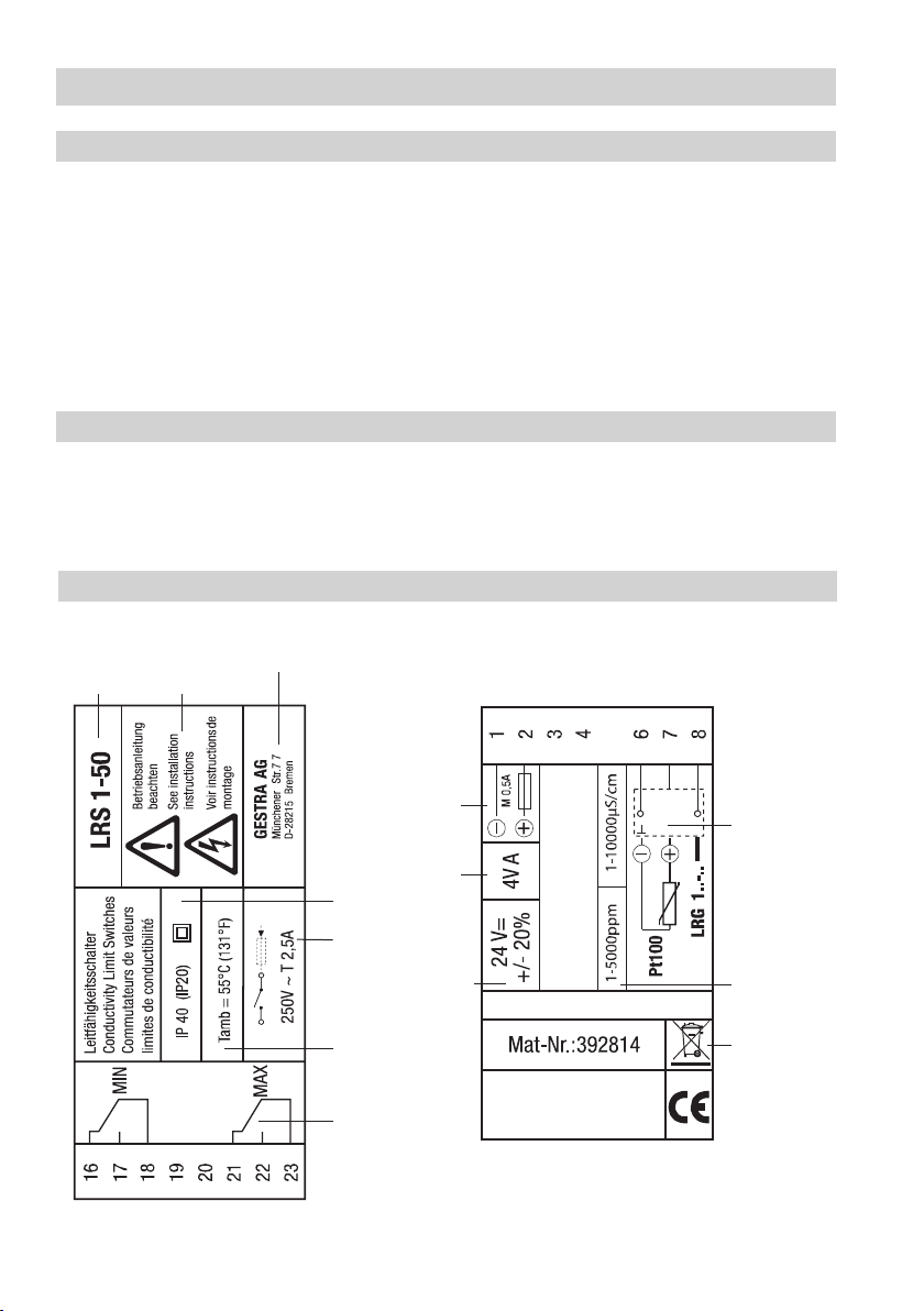
The conductivity switch LRS 1-50 in conjunction with conductivity electrodes LRG 1.-.. is used as limit
switch, for instance in steam boilers, (pressurized) hot-water installations and condensate and feedwa-
ter tanks. The conductivity switch detects and indicates a MIN and a MAX conductivity limit.
The conductivity switch LRS 1-50 is designed for use in combination with the following conductivity
electrodes: LRG 12-1, LRG 16-4, LRG 16-9, LRG 17-1 and LRG 19-1.
The conductivity switch LRS 1-50 in conjunction with the conductivity electrode LRG 1.-.. measures
the electrical conductivity in conductive liquids. The conductivity electrodes LRG 12-2, LRG 16-4, LRG
17-1, LRG 19-1 or the LRG 16-9 with integrated resistance thermometer for detecting the fluid tem-
perature can be used with the conductivity switch. To measure the temperature you can also use a
separate resistance thermometer Pt 100.
When connecting the conductivity electrode LRG 1.-.. a reference measurement is taken and by set-
ting the correction factor CF accordingly the conductivity readings are adapted to the specific condi-
tions of the installation
If a resistance thermometer is used, not only the electrical conductivity but also the water temperature
will be measured. The conductivity readings can then be referenced to the standard reference tem-
perature of 25 °C and the conductivity value will be automatically compensated for temperature.
For this purpose the water temperature is constantly measured by the conductivity switch and the con-
ductivity reading is automatically compensated as a function of the adjusted temperature coefficient tC
(%/°C). Even if the temperature changes, thanks to the adjusted linear temperature compensation, the
measured value is referenced to 25 °C over the whole measuring range and indicated on the 7-seg-
ment LED display.
The MAX /MIN limits can be variably adjusted within the measuring range.
When the MIN or MAX limit is reached, the MIN or MAX output contact is switched over and MIN
or MAX LED is illuminated. The equipment will be reset once the value passes outside the preset
hysteresis.
Any faults or malfunctions in the conductivity electrode, the electrical connection or the settings will
be indicated by the 7-segment LED display. In the event of a malfunction a MIN and MAX alarm will be
triggered.
If an error occurs in the conductivity switch LRS 1-50, MIN and MAX alarms are raised and the system
is restarted.
Parameter settings can be changed or a MIN/MAX alarm be simulated by operating the rotary button.
The electrical conductivity is measured in µS/cm. In some countries ppm (parts per million) is used
instead. Conversion: 1µS/cm = 0.5 ppm. The conductivity switch can be adjusted accordingly.
Function

5
Safety note
The equipment must only be installed, wired and commissioned by qualified and competent staff.
Retrofitting and maintenance work must only be performed by qualified staff who - through adequate
training - have achieved a recognised level of competence.
Danger
The terminal strips of the equipment are live during operation.
This presents the danger of electric shock!
Always cut off power supply to the equipment before mounting, removing or connect-
ing the terminal strips!
Attention
The name plate specifies the technical features of the equipment. Note that any piece of
equipment without its specific name plate must neither be commissioned nor operated.
Important notes - continued -

6
Directives and standards
ATEX (Atmosphère Explosible)
According to the European Directive 2014/34/EU the equipment must not be used in explosion risk areas.
LV (Low Voltage) Directive and EMC (Electromagnetic Compatibility)
The equipment meets the requirements of the Low Voltage Directive 2014/35/EU and the EMC Direc-
tive 2014/30/EU.
Note
The conductivity electrodes LRG 12-1, LRG 16-4, LRG 16-9, LRG 17-1 and LRG 19-1 are
simple items of electrical equipment as specified in EN 60079-11 section 5.7. According to
the European Directive 2014/34/EU the equipment must be equipped with approved Zener
barriers if used in potentially explosive areas. Applicable in Ex zones 1, 2 (1999/92/EC). The
equipment does not bear an Ex marking.
Note on the Declaration of Conformity / Declaration by the Manufacturer
For details on the conformity of our equipment according to the European Directives see our Declaration of
Conformity or our Declaration of Manufacturer.
The current Declaration of Conformity / Declaration of Manufacturer are available in the Internet under
www.gestra.com/documents or can be requested from us.
VdTÜV Bulletin "Water Monitoring 100"
The conductivity switch LRS 1-50 in conjunction with the conductivity electrode LRG 1.-.. is type ap-
proved according to VdTÜV Bulletin "Water Monitoring 100".The VdTÜV Bulletin "Water Monitoring
100" states the requirements made on water monitoring equipment.
EU Pressure Equipment Directive 2014/68/EU
The conductivity control & monitoring equipment LRG 1.-.., LRS 1-5.., LRR 1-5.. meets the safety
requirements of the Pressure Equipment Directive (PED). The conductivity control & monitoring
equipment is EC type approved according to EN 12952/EN 12953. These Directives state, among other
things, the requirements made on limiting systems and equipment for steam boiler plants and
(pressurised) hotwater installations.

7
LRS 1-50
Technical data
Supply voltage
24 VDC +/– 20%
Fuse
external 0.5 A (semi-delay)
Power consumption
4 VA
Connection of conductivity electrode
1 input for conductivity electrode LRG 12-1, LRG 16-4, LRG 17-1 and LRG 19-1
(cell constant 1 cm-1), 3 poles with screen
1 input for conductivity electrode LRG 16-9 (cell constant 0.5 cm-1), with integrated resistance
thermometer Pt 100, 5 poles with screen.
Measuring voltage
0.8 Vss, pulse duty factor tv = 0.5, frequency 20-10000 Hz.
Measuring range
1 to 10,000 μS/cm at 25 °C or 1 to 5,000 ppm at 25 °C.
Switching hystereses
MIN limit: + 3 % of the adjusted MIN limit,
MAX limit: – 3 % of the adjusted MAX limit.
Outputs
LRS 1-50: 2 volt-free change-over contacts, 8 A 250 V AC / 30 V DC cos ϕ= 1.
Provide inductive loads with RC combinations according to manufacturer's specification to ensure
interference suppression
Indicators and adjusters
1 rotary button with integrated push-button for parameter setting and testing MAX /MIN alarm,
1 seven-segment LED display, four digits,
2 red LEDs for MAX/MIN alarm,
1 four-pole code switch for configuration settings
Housing
Housing material: base: polycarbonate, black; front: polycarbonate, grey
Conductor size: 1 x 4.0 mm2solid, per wire, or
1 x 2.5 mm2per stranded wire with sleeve to DIN 46228 or
2 x 1.5 mm2per stranded wire with sleeve to DIN 46228 (min. ∅0.1 mm)
Terminal strips can be detached. Fixing of housing: Mounting clip on supporting rail TH 35, EN 60715
Electrical safety
Pollution degree 2 for installation in control cabinet with protection IP 54, completely insulated
Protection
Housing: IP 40 to EN 60529,
Terminal strip: IP 20 to EN 60529
Weight
approx. 0.2 kg
Ambient temperature
when system is switched on: 0° ... 55 °C, during operation: -10 ... 55 °C
Transport temperature
–20 ... +80 °C (<100 hours), defrosting time of the de-energized equipment before it can be put into
operation: 24 hours.

8
LRS 1-50 - continued -
Technical data
Scope of supply
LRS 1-50
1 Conductivity switch LRS 1-50
1 Adhesive label ppm
1 Installation manual
Name plate / marking
Name plate (on top)
Safety
note
Output
contacts
Ambient
temperature
Type
designation
Manufacturer
Supply
voltage
Fuse,
provided
on site
Power
consumption
Disposal note
Type approval no.
Connection
for conductivity
electrode
Type approval no.
Measuring
range
External fuse for
output contacts
Protection
Name plate (at the bottom)
Fig. 1
Storage temperature
–20 ... +70 °C, defrosting time of the de-energized equipment before it can be put into operation:
24 hours.
Relative humidity
max. 95%, no moisture condensation
Approvals:
TÜV certificate VdTÜV Bulletin "Wasserüberwachung 100" (= Water Monitoring 100):
Requirements made on water monitoring equipment
Type approval: TÜV · WÜL · XX-XXX (see name plate).
- continued -

9
In control cabinet: Mounting the conductivity switch
Dimensions LRS 1-50
Fig. 2
1 Upper terminal strip
2 Lower terminal strip
Key
Installation in control cabinet
The conductivity switch LRS 1-50 is clipped onto the support rail type TH 35, EN 60715 in the control
cabinet. Fig. 1 4
3 Housing
4 Supporting rail type TH 35, EN 60715
43
1
2
46
74
120 15

10
In control cabinet: Wiring the conductivity switch
Wiring diagram for conductivity switch LRS 1-50
5 Connection of supply voltage 24 V DC
with fuse 0.5 A (semi-delay), provided on site
6 Conductivity electrode LRG 1.-.. (Terminal 6/7: A
resistance thermometer can be connected)
7 Conductivity electrode LRG 16-9 with integrated
resistance thermometer
Key
Fig. 3 8
MIN MAXMIN MAX
M 0.5 A
(semi-
delay)
M 0.5 A
(semi-
delay)
55
09 9 0
8
6
7
8 Central earthing point (CEP) in control
cabinet
9 MIN output contact
0 MAX output contact

11
In control cabinet: Wiring the conductivity switch
Connection of supply voltage
The equipment is supplied with 24 V DC and fused with an external semi-delay fuse 0.5 A. Please use a
safety power supply unit with safe electrical isolation.
The power supply unit must be electrically isolated from dangerous contact voltages and must meet at
least the requirements on double or reinforced isolation according to one of the following standards:
DIN EN 50178, DIN EN 61010-1, DIN EN 60730-1 or DIN EN 60950.
Connecting conductivity electrode LRG 12-2, LRG 16-4, LRG 17-1 and LRG 19-1,
resistance thermometer TRG 5-..
To connect the equipment use screened multi-core control cable with a min. conductor size 0.5 mm2,
e. g. LiYCY 2 x 0.5 mm2.
Wire terminal strip in accordance with the wiring diagram. Fig. 3
Connect the screen only once to the central earthing point (CEP) in the control cabinet.
Make sure that connecting cables leading to the equipment are segregated and run separately from
power cables.
Connecting output contacts
Wire the upper terminal strip 1(terminals 16-23) according to the desired switching functions.
Provide an external slow-blow fuse 2.5 A for the output contacts.
When switching off inductive loads, voltage spikes are produced that may impair the operation of con-
trol and measuring systems. Connected inductive loads must be provided with suppressors such as RC
combinations as specified by the manufacturer.
When used as conductivity limiter, the conductivity switch LRS 1-50 does not interlock automatically
when readings exceed the MAX limit.
If an interlock function is required for the installation it must be provided in the follow-up circuitry
(safety circuit). The circuitry must meet the requirements of the EN 50156.
The conductivity electrode LRG 16-9 is equipped with a sensor plug-in connection type M 12, with 5
poles, A-coded, pin assignment see Fig. 3. For connecting the equipment preconfigured control cable
assemblies (with male and female connectors) of various lengths are available as add-on equipment.
To connect the conductivity switch LRS 1-50 remove the connector and wire the terminal strip accord-
ing to the wiring diagram. Fig. 3.
Connect the screen only once to the central earthing point (CEP) in the control cabinet.
If you do not use the prefabricated control cable assembly, use screened five-core control cable, e. g.
LiYCY 5 x 0.5 mm2, for connecting the equipment. In addition, connect at the electrode end a screened
female connector to the control cable.
Make sure that connecting cables leading to the equipment are segregated and run separately from
power cables.
Connection of conductivity electrode LRG16-9
Attention
n Do not use unused terminals as support point terminals.
- continued -

12
Tools
n Screwdriver, size 3.5 x 100 mm, completely insulated according to VDE 0680-1.
Attention
n To commission the equipment please refer to the installation & operating manuals for
LRG 12-2, LRG 16-4, LRG 16-9, LRG 17-1, LRG 19-1 and TRG 5-.. .
n Make sure that connecting cables leading to the equipment are segregated and run
separately from power cables.
n Check the connection of the screen to the central earthing point (CEP) in the control
cabinet.
In the plant:
Wiring the conductivity electrode
Connecting conductivity electrode LRG 12-2, LRG 16-4, LRG 17-1 and LRG 19-1,
resistance thermometer TRG 5-..
To connect the equipment use screened multi-core control cable with a min. conductor size 0.5 mm2,
e. g. LiYCY 3 x 0.5 mm2.
Wire terminal strip in accordance with the wiring diagram. Fig. 3
Connect the screen only once to the central earthing point (CEP) in the control cabinet.
Max. cable length between conductivity electrode / resistance thermometer and conductivity
switch: 30 m, with conductivities from 1 to 10 μS/cm: max. 10 m.
Make sure that connecting cables leading to the equipment are segregated and run separately from
power cables.
The conductivity electrode LRG 16-9 is equipped with a sensor plug-in connection type M 12, with 5
poles, A-coded, pin assignment see Fig. 3. For connecting the equipment preconfigured control cable
assemblies (with male and female connectors) of various lengths are available as add-on equipment.
Note that the recommended control cable is not UV-resistant and, if installed outdoors, must be
protected by a UV-resistant plastic tube or cable duct.
To connect the conductivity switch LRS 1-50 remove the connector and wire the terminal strip accord-
ing to the wiring diagram. Fig. 3
Connect the screen only once to the central earthing point (CEP) in the control cabinet.
If you do not use the prefabricated control cable assembly, use screened five-core control cable, e. g.
LiYCY 5 x 0.5 mm2, for connecting the equipment. In addition, connect at the electrode end a screened
female connector to the control cable.
Max. cable length between conductivity electrode and switch: 30 m, with conductivities from 1
to 10 μS/cm: max. 10 m.
Make sure that connecting cables leading to the equipment are segregated and run separately from
power cables.
Connection of conductivity electrode LRG16-9

13
Changing factory settings
The upper terminal strip of the equipment is live during operation.
This presents the danger of electric shock!
Always cut off power supply to the equipment before mounting, removing or connect-
ing the terminal strips!
Danger
Switch selection of unit of measurement
The electrical conductivity is measured in µS/cm. In some countries ppm (parts per million) is used
instead. Conversion: 1 µS/cm = 0.5 ppm. Use the code switch ato set the desired unit of measurement.
This unit setting is then applicable for all conductivity readings and settings. If you choose ppm as unit of
measurement, please stick the adhesive label supplied with the equipment onto the unit specification on
the housing.
To change the setting proceed as follows:
n Insert a screwdriver to the right and left of the arrow markings between the terminal strip and the
front frame.
n Unlock terminal strip on the left and right side For this purpose move screwdriver in direction of the
arrow.
n Remove the terminal strip
n Set switch S4 of code switch ato ON = ppm (parts per million)
n Re-attach lower terminal strip.
n Apply supply voltage. Equipment is restarted.
Fig. 4
a
Attention
Do not change the code switch asettings of S1, S2 and S3 .
Factory setting
Conductivity Switch LRS 1-50
n MAX switchpoint AL.Hi = 6000 μS/cm
n MIN switchpoint AL.Lo = 500 μS/cm
n Switching hysteresis: +/– 3% (fixed setting)
n Correction factor CF: 1
n Temperature compensation inP: No
n Temperature coefficient tC: 2.1 % / °C
n Code switch a: All switches are set to
OFF.

14
Operating the conductivity switch
Key to codes on seven-segment display
Code Description
Indicated when rotary button is turned to the right:
AL.Hi Alarm High MAX switchpoint adjustable between 1 and 9999 μS/cm
AL.Lo Alarm Low MIN switchpoint
CF Correction Factor Correction factor, adjustable between 0.05 and 5,000, adjustable
in increments of 0.001
inP Input Pt 100 Temperature compensation YES (no)
tC Temperature coefficient Temperature coefficient Tk0.0 – 3.0 % per °C,
adjustable in increments of 1 %.
tESt Test Tests output relays
Indicated when in parameterization mode:
quit Quit Input not confirmed
done Done Input confirmed
Indicated if malfunctions occur:
E.001 Error Temperature sensor defective, temperature reading too low
E.002 Error Temperature sensor defective, temperature reading too high
E.005 Error Sensor defective, measured value too low
E.006 Error Sensor defective, measured value too high
E.013 Error MIN switchpoint above MAX switchpoint
Fig. 5
MAX LED
red
MIN LED
red
Seven-segment
display
Rotary button with
integrated push-
button
5432

15
Start
Activity Display Function
Switch on supply voltage.
Water level between MIN and
MAX.
Seven-segment display shows
equipment and software ver-
sion.
System test, takes approx. 3 sec.
Seven-segment display shows
actual value System switches to operating mode
Setting parameters
Activity Seven-segment display Function
Turn rotary button until the
desired parameter is indicated.
Display toggles between pa-
rameter and the saved value
setting.
For selecting the parameter
Press and hold down the push-
button (of the rotary button) First digit (0000) flashing. Parameterization mode active. You can change
the first digit.
Turn rotary button. A new value is indicated. To increase the value turn rotary button to the
right, to decrease turn it to the left.
Press push-button.
Each time you press the but-
ton the system moves to the
next digit.
2nd, 3rd or 4th digit is flashing.
(from right to left)
2nd, 3rd or 4th digit can be changed by turning
the rotary button. To increase the value turn
rotary button to the right, to decrease turn it to
the left.
If no further operation is per-
formed:
"quit" is indicated for a mo-
ment. Then the display toggles
between parameter and the old
value setting.
The system switches automatically back to
parameter and the input is not confirmed.
After the input has been fin-
ished: Press and hold down the
push-button.
"done" is indicated for a mo-
ment. Then the display toggles
between parameter and the
new value setting.
The input is confirmed and the system switches
automatically back to parameter.
Turn rotary button until the next parameter is indicated.
Or turn the rotary button until the actual value is shown.
If no operation is performed the actual value will be indicated automatically after 30 sec.
Commissioning procedure
Setting parameters
Fig. 5
MAX LED
red
MIN LED
red
Seven-segment
display
Rotary button with
integrated push-
button
5432

16
Commissioning
Setting switchpoints and parameters
Setting MIN/MAX switchpoints
Activity Function
Select parameter AL.Lo, set the desired conductivity
and save the setting.
Adjust MIN limit between 1 and 9999 μS/cm or 1 and
5000 ppm.
Select parameter AL.HI, set the desired conductivity and
save the setting.
Adjust MAX limit between 1 and 9999 μS/cm or 1 and
5000 ppm.
Conductivity electrode LRG 1.-..: Setting the correction factor
Select correction factor CF, set the required value and
save the setting.
Once the operating temperature is reached measure the
electrical conductivity of a water sample (at 25°C). Set
the correction factor (in increments) until the indicated
actual value agrees with the reference measured value.
As a result the conductivity readings will be adapted to
the specific conditions of the installation and any devia-
tions during operation will be compensated for.
Conductivity electrode LRG 1.-.. with separate resistance thermometer and LRG 16-9
Enable temperature compensation
Select setting inP and turn rotary button to the right.
The word "YES" appears. Save the setting.
Setting the temperature coefficient tC
Select temperature coefficient tC, set the required
percentage value and save the setting.
Once the operating temperature is reached measure
the electrical conductivity of a water sample (at 25°C).
Set the temperature coefficient (in increments) until the
indicated actual value agrees with the reference meas-
ured value.
If required:
Select correction factor CF, set the required value and
save the setting.
During operation the indicated conductivity reading may
deviate from the reference value due to e. g. dirt deposits
or contamination. Change the correction factor (in incre-
ments) until the indicated actual value agrees with the
reference measured value.

17
Operation, alarm and test
Checking indication and functions of MIN / MAX output contacts
Operation
Activity Display Function
Conductivity between MIN and
MAX.
The actual value is shown on
the seven-segment display.
MIN and MAX LEDs are not
illuminated.
MIN output contact 16/18 open, 17/18 closed.
MAX output contact 21/23 open, 22/23 closed.
MIN alarm
Reading below MIN conductiv-
ity limit MIN LED illuminated red MIN output contact 16/18 closed, 17/18 open.
MAX alarm
Switchpoint "MAX conductiv-
ity" exceeded. MAX LED illuminated red MAX output contact 21/23 closed, 22/23 open.
Testing MIN alarm and MAX alarm
Activity Display Function
During operation:
Conductivity between MIN
and MAX.
Select parameter Test. Press
and hold down push-button.
Seven-segment display: Test
is flashing
MAX LED is illuminated red for
3 sec. MAX output contact 21/23 closed, 22/23 open.
MIN and MAX LEDs not illumi-
nated for 1 sec.
MIN output contact 16/18 open, 17/18 open.
MAX output contact 21/23 open, 22/23 closed.
MIN LED is illuminated red for
3 sec. MIN output contact 16/18 closed, 17/18 open.
Test finished, release push-
button. Seven-segment display:
Test is indicated.
Note: If you continue to hold down the push-button, a new test is started. You can
abort the test any moment by releasing the push-button.
Turn the rotary button until the actual value is shown.
If no operation is performed the actual value will be indicated automatically after 30 sec.
Fig. 5
MAX LED
red
MIN LED
red
Seven-segment
display
Rotary button with
integrated push-
button
5432

18
Attention
Before carrying out the fault diagnosis please check:
Supply voltage:
Is the equipment supplied with the mains voltage specified on the name plate?
Wiring:
Is the wiring in accordance with the wiring diagram?
Troubleshooting
Indication, diagnosis and remedy
Attention
n Please refer to the installation & operating manuals for LRG 12-2, LRG 16-4,
LRG 16-9, LRG 17-1, LRG 19-1 and TRG 5-.. for further fault-finding and troubleshooting.
Note
If a malfunction occurs in the conductivity switch, MIN and MAX alarms will be triggered
and the equipment is restarted.
Should this happen over and over again, replace the equipment with a new one.
Faults indicated by the seven-segment display
Error code Error Remedy
E.001 Temperature sensor defective, temperature
reading too low Check resistance thermometer, conductivity electrode
LRG 16-9 and, if necessary, replace it with a new one.
Check wiring (short circuit, interruption?)
E.002 Temperature sensor defective, temperature
reading too high
E.005 Conductivity electrode defective, measured
value too low.
Check conductivity electrode and, if necessary, replace
it. Check electrical connection.
E.006 Conductivity electrode defective, measured
value too high.
Check conductivity electrode and, if necessary, replace
it. Check electrical connection.
E.013 MIN switchpoint above MAX switchpoint Re-adjust the switchpoints.
In the event of a malfunction a MIN and MAX alarm will be triggered.

19
Action against high frequency interference
High frequency interference can occur for example as a result of out-of-phase switching operations.
Should such interference occur and lead to sporadic failures, we recommend the following actions in
order to suppress any interference.
n Provide inductive loads with RC combinations according to manufacturer's specification to ensure
interference suppression.
n Make sure that all connecting cables leading to the conductivity electrode are segregated and run
separately from power cables.
n Increase the distance to sources of interference.
n Check the connection of the screen. Check the connection of the screens of the equipment as stipu-
lated in the respective installation & operating manuals. If equipotential bonding currents are to be
expected (e. g. in outdoor installations) connect screen only at one end.
n HF interference suppression by means of hinged-shell ferrite rings.
Further Notes
n Switch off supply voltage and cut off power supply to the equipment.
n Remove the lower and upper terminal strips Fig. 6
n Insert a screwdriver to the right and left of the arrow markings between the terminal strip and the
front frame.
n Unlock terminal strip on the left and right side For this purpose move screwdriver in direction of
the arrow .
n Remove the terminal strip
n Release the white fixing slide at the bottom of the equipment and take the equipment off the support-
ing rail.
Decommissioning / replacing the equipment
Disposal
For the disposal of the equipment observe the pertinent legal regulations concerning waste disposal.
If faults occur that are not listed above or cannot be corrected, please contact our service centre or
authorized agency in your country.
Fig. 6

819223-02/02-2017cm (808884-02) · GESTRA AG · Bremen · Printed in Germany
GESTRA AG
Münchener Straße 77
28215 Bremen
Germany
Telefon +49 421 3503-0
Telefax +49 421 3503-393
E-mail [email protected]
Web www.gestra.de
Agencies all over the world: www.gestra.de
Other manuals for LRS 1-50
2
Table of contents
Other GESTRA Switch manuals

GESTRA
GESTRA LRS 1-50 User manual

GESTRA
GESTRA TRS 5-52 User manual

GESTRA
GESTRA NRS 1-2 User manual

GESTRA
GESTRA NRS 2-1 Quick guide

GESTRA
GESTRA NRS 1-51 User manual

GESTRA
GESTRA TRS 5-50 User manual

GESTRA
GESTRA NRS 2-50 User manual

GESTRA
GESTRA LRGS 15-1 User manual

GESTRA
GESTRA NRS 1-50 User manual

GESTRA
GESTRA NRS 1-50 User manual

GESTRA
GESTRA URS 2 User manual

GESTRA
GESTRA NRGS 15-1 User manual

GESTRA
GESTRA NRS 2-50 User manual

GESTRA
GESTRA NRS 1-8 User manual

GESTRA
GESTRA NRS 1-50 User manual

GESTRA
GESTRA NRS 1-56 User manual

GESTRA
GESTRA NRS 1-50 Series User manual

GESTRA
GESTRA NRS 1-56 User manual

GESTRA
GESTRA LRS 1-50 User manual

GESTRA
GESTRA NRS 1-51 User manual