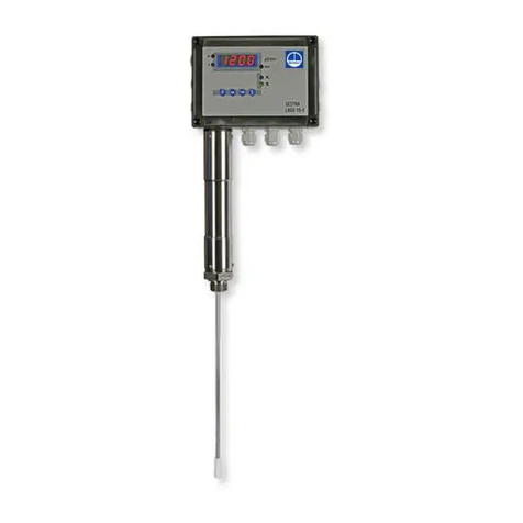
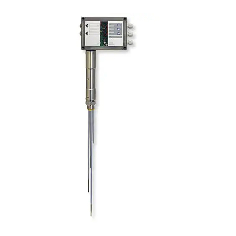
GESTRA NRGS 15-1 User manual

Original Installation &
Operating Manual
850690-00
Level Switch
NRGS 15-1
EN (USA)
English

2NRGS 15-1 - USA - Installation & Operating Manual - 850690-00
Contents
Content of this Manual......................................................................................................................... 4
Scope of supply, product package....................................................................................................... 4
How to use this Manual........................................................................................................................ 5
Illustrations and symbols used............................................................................................................ 5
Hazard symbols in this Manual............................................................................................................ 5
Types of warning .................................................................................................................................. 6
Specialist terms, abbreviations ........................................................................................................... 7
Usage for the intended purpose........................................................................................................... 8
Applicable directives and standards.............................................................................................. 8
Improper use ........................................................................................................................................ 8
Basic safety information ...................................................................................................................... 9
Required personnel qualifications..................................................................................................... 10
Notes on product liability................................................................................................................... 10
Function .............................................................................................................................................. 11
Technical data .................................................................................................................................... 12
Rating plate, identification................................................................................................................. 14
Overall view of the NRGS 15-1 ........................................................................................................... 15
Dimensions of the NRGS 15-1............................................................................................................ 16
Setting functions ................................................................................................................................ 17
Selecting a function ....................................................................................................................... 17
Setting functions............................................................................................................................ 19
Setting the time delay.................................................................................................................... 19
Setting the response sensitivity...................................................................................................... 20
Preparing for installation ................................................................................................................... 21
Installation.......................................................................................................................................... 22
Installing the NRGS 15-1, step 1 .................................................................................................... 24
Functions table .............................................................................................................................. 24
Installing the NRGS 15-1, step 2 .................................................................................................... 25
Installation examples with dimensions............................................................................................. 26
Electrical connection.......................................................................................................................... 28
Rotating the terminal box............................................................................................................... 28
Connecting the NRGS 15-1 level switch......................................................................................... 28
Wiring diagram .............................................................................................................................. 29

3NRGS 15-1 - USA - Installation & Operating Manual - 850690-00
Contents
Bringing into service .......................................................................................................................... 30
Checking the electrical connection................................................................................................. 30
Switching on the power supply ...................................................................................................... 30
Checking switchpoints and functions ............................................................................................. 30
Fault indications and troubleshooting............................................................................................... 31
Indications, diagnosis and corrective action ................................................................................... 31
Replacing the electronic circuit board ............................................................................................ 34
Taking out of service.......................................................................................................................... 35
Removing the level switch ............................................................................................................. 35
Disposal .............................................................................................................................................. 36
Returning decontaminated equipment.............................................................................................. 36
UL components................................................................................................................................... 36
Annex .................................................................................................................................................. 37
Setting other functions................................................................................................................... 37
Installation in non-metallic tanks ................................................................................................... 37

4NRGS 15-1 - USA - Installation & Operating Manual - 850690-00
Content of this Manual
Product:
■ Level switch NRGS 15-1
First edition:
BAN 850690-00/08-2021cm
© Copyright
All rights reserved. Any misuse, particularly reproduction and dissemination to third parties, is not
permitted. The General Terms & Conditions of GESTRA AG apply.
Scope of delivery, product package
■ 1 x NRGS 15-1 level switch, comprising
■ 1 x level electrode with four tips
■ 1 x terminal box with level switch
■ 1 x Installation & Operating Manual

5NRGS 15-1 - USA - Installation & Operating Manual - 850690-00
How to use this Manual
This Installation & Operating Manual describes the correct use of the NRGS 15-1 level switch. It
applies to persons who integrate this equipment in control systems, install, bring into service, op-
erate, maintain and dispose of this equipment. Anyone carrying out the above-mentioned activities
must have read this Installation & Operating Manual and understood its contents.
■ Read this Manual in full and follow all instructions.
■ Please also read the instructions for use of any accessories.
■ The Installation & Operating Manual is part of the product package. Keep it in an easily acces-
sible location.
Availability of this Installation & Operating Manual
■ Make sure this Installation & Operating Manual is always available to the operator.
■ If you pass on or sell the equipment to a third party, please also hand over the Installation &
Operating Manual.
Hazard symbols in this Manual
Danger zone, dangerous situation
Illustrations and symbols used
1. Action to be taken
2.
■ Lists
◆ Bullet points in lists
A Keys to illustrations
Additional
information
Read the relevant
Installation & Operating Manual

6NRGS 15-1 - USA - Installation & Operating Manual - 850690-00
Types of warning
DANGER
Warning of a dangerous situation that results in death or serious injury.
WARNING
Warning of a dangerous situation that may possibly result in death or serious injury.
CAUTION
Warning of a situation that may result in minor or moderate injury.
ATTENTION
Warning of a situation that results in damage to property or the environment.

7NRGS 15-1 - USA - Installation & Operating Manual - 850690-00
Specialist terms, abbreviations
Here, we explain some abbreviations, specialist terms, etc., which are used in this Manual.
NRGT .. / NRR.. / NRS.. / URS .. / URB .. / SRL .. / etc.
Equipment and type designations of GESTRA AG.
SELV
Safety Extra Low Voltage
Operating point (of the plant)
The operating point describes the operating parameters within which a plant or boiler is operated
in its nominal range. In a steam boiler, for example, these parameters would be
output, pressure, and temperature.
The design data may be a lot more stringent, however.
A boiler that is operated at 145psi (10bar) and 356°F (180°C) may be designed to withstand a
pressure of 870psi (60bar) and a temperature of 527°F (275°C), for example, which is therefore
not necessarily its operating point.

8NRGS 15-1 - USA - Installation & Operating Manual - 850690-00
Usage for the intended purpose
The NRGS 15-1 level switch indicates when four different water levels have been reached, and
acts as a water level controller with MIN and MAX alarm, e.g. in steam boilers and hot water
installations and also in condensate and feedwater tanks. The NRGS 15-1 is classified as an
operating control in accordance with UL60730-1.
Improper use
There is a danger of death due to explosion if the equipment is used in potentially
explosive atmospheres.
Do not use the equipment in potentially explosive atmospheres.
Do not bring any equipment into service that does not have its own specific rating
plate.
The rating plate indicates the technical features of the equipment.
Applicable directives and standards
The NRGS 15-1 level switch has been tested and approved for use in the scope governed by the
following directives and standards:
Standards:
■ UL 60730-1 and CAN/CSA E60730-1
General Requirements for Automatic Electrical Controls
■ UL 60730-2-15 and CAN/CSA E60730-2-15
Requirements for Automatic Electrical Water Level Sensing Controls

9NRGS 15-1 - USA - Installation & Operating Manual - 850690-00
Danger to life from scalding! Do not remove the level electrode under
pressure. Steam or hot water can spurt forcefully out of the equipment.
■ Only remove the level electrode at 0psi (0bar) boiler pressure.
Risk of severe burns! Do not perform work on a level electrode that is still hot. The
level electrode gets very hot during operation.
■ Allow the level electrode to cool.
■ Always wait for the level electrode to cool before performing any installation and
maintenance work.
Danger to life from electric shock during work on electrical systems.
■ Always switch off the voltage to the plant before performing connection work.
■ Check that the plant is not carrying live voltage before commencing work.
Danger to life! Hot steam or hot water can suddenly escape from a faulty
NRGS 15-1 level switch.
Shocks and impacts during transport or installation can result in damage to or leaks in
the level electrode, causing pressurized hot steam or hot water to escape through the
pressure relief hole.
■ To prevent damage during transport and installation, do not expose the electrode
rod to major shocks or impacts.
■ Before and after installation, check that the level electrode is completely undamaged.
■ Check that the level electrode is not leaking when bringing into service.
Attempts to repair the equipment will cause the plant to become unsafe.
■ The NRGS 15-1 level switch may only be repaired by the manufacturer, GESTRA AG.
■ Only replace faulty equipment with identical equipment from GESTRA AG.
Basic safety information

10 NRGS 15-1 - USA - Installation & Operating Manual - 850690-00
Required personnel qualifications
Activity Personnel
Integration in control system Specialist staff Plant designer
Installation/electrical
connection/
bringing into service
Specialist staff
The equipment may only be installed, wired
and brought into service by qualified and
competent staff.
Operation Boiler service technician Staff trained by the plant operator.
Maintenance work Specialist staff
Maintenance and refits may only be
performed by authorized staff who have
undergone specific training.
Refits Specialist staff Persons trained by the plant operator to work
with pressure and temperature.
Notes on product liability
The manufacturer cannot accept any liability for damages resulting from improper use of the
equipment.

11NRGS 15-1 - USA - Installation & Operating Manual - 850690-00
Function
The NRGS 15-1 level switch is a compact system consisting of a level electrode with four tips
and an integrated level switch. The equipment only functions if used in water with a minimum
electrical conductivity of > 0.25ppm (0.5µS/cm) at 77°F (25°C).
In the level switch, a time-delayed switching channel, an output relay and a signal LED are
assigned to each of the four electrode tips.
The function of switching channels 1 and 4 is fixed, while switching channels 2 and 3 are defined
via the code switch. The switchpoints of each switching channel depend on the level and are
determined by shortening the relevant electrode tips.
The following functions are possible:
■Electrode rod 1 exposed / switching channel 1 energizes relay 1 = low water 1
■Electrode rod 2 exposed / switching channel 2 energizes relay 2 = low water 2
■Electrode rod 3 exposed or immersed / switching channel 3 energizes relay 3
(time-dependent) = timed pump control (fill/discharge control)
■Electrode rods 2 and 3 exposed or immersed / switching channel 3 energizes relay 3
= on/off pump control (fill/discharge control)
■Electrode rod 4 immersed / switching channel 4 energizes relay 4 = high water

12 NRGS 15-1 - USA - Installation & Operating Manual - 850690-00
Technical data
Service pressure
363psi at 435°F (25bar at 224°C)
Mechanical connection
Thread 1" - 11.5 NPT
Materials
Screw-in body: 1.4404 / F316L
Electrode rods: 1.4571, CrNiMoTi17-12-2
Electrode rod insulation: PTFE
Spacer: PTFE
Terminal box: Polycarbonate
Electrode rods
Length supplied: 39.37 in (1000 mm)
Diameter: 0.2 in (5 mm)
Supply voltage
NRGS 15-1 / 240 VAC: 240 V +10/–15 %, 50/60 Hz
NRGS 15-1 / 120 VAC: 120 V +10/–15 %, 50/60 Hz
Power consumption
3 VA
Fuse
External 63 mA, slow blow, at 240 V
External 125 mA, slow blow, at 120 V
Response sensitivity [electrical conductivity of water at 77°F (25°C)]
> 5 ... < 5000 ppm (> 10 ... < 10000 µS/cm) (switch-selectable)
Electrode voltage
20 Vss
Output
4 volt-free relay contacts,
8 A 250 V AC / 30 V DC cos ϕ= 1 (IEC 61810)
Ensure interference suppression (RC combination) for contactor.
Energizing/de-energizing delay
Relays 1 and 2: 1s, fixed
Relay 3: 0-30s, set via potentiometer
Relay 4: 3s, fixed
Indicators and controls
3 red LEDs to indicate “Low level alarm 1 + 2 / High level”.
1 yellow LED to indicate “Pump on”.
1 green LED to indicate “Mains supply on”.
1 10-pole code switch to select the sensitivity and define the functions.
1 potentiometer for setting the time delay (0 to 30 s)

13NRGS 15-1 - USA - Installation & Operating Manual - 850690-00
Technical data
Cable entry/electrical connection
3 cable glands with integrated cable clamp (M 16).
1 2-pole terminal strip for power supply.
1 12-pole terminal strip for connecting the control cables.
Terminal strips are detachable screw-type models with conductor size ≥ AWG 16 (≤ 1.5 mm).
Protection
NEMA type 4 according to NEMA 250
IP 65 according to EN 60529
Protection class
Class II with functional ground via boiler wall
Installation class
3
Overvoltage category
CAT III
Admissible ambient temperature
at power-on 32° ... 158°F (0° ... 70°C)
during operation 14° ... 158°F (-10° ... 70°C)
Transport temperature
-4° ... +176°F (-20° ... +80°C) (< 100 hours), only switch on after a defrosting period of 24
hours.
Storage temperature
-4° ... 158°F (-20° ... +70°C), only switch on after a defrosting period of 24 hours.
Relative humidity
Max. 95%, no moisture condensation
Weight
Approx. 3.08lb (1.4kg)
Other information
Independently mounted Type 1.B action operating control
Pollution degree 2, impulse voltage 4000 V

14 NRGS 15-1 - USA - Installation & Operating Manual - 850690-00
Before removing cover, isolate from
power supplies. See installation
instructions!
Avant d'ouvrir le couvercle
dèconnecter complètement l'appareil.
Voir instructions de montage.
Vor Öffnen des Deckels, Gerät
freischalten! Betriebsanleitung
beachten!
120VAC 50/60Hz 3VA
Pmax
Tmax
NRGS 15-1 / 120VAC
0-30s 0,5/10µS/cm
Niveauschalter
Level switch
Commutateur de niveau
Tamb = 158°F (70°C)
IP65
1-11,5 NPT 1.4404/F316L
363psi (25 bar)
435°F (224°C)
Mat.-Nr.: XXXXXX
GESTRA AG
Münchener Str. 77
28215 Bremen
Made in Germany
250V ~ T2,5A
Before removing cover, isolate from
power supplies. See installation
instructions!
Avant d'ouvrir le couvercle
dèconnecter complètement l'appareil.
Voir instructions de montage.
Vor Öffnen des Deckels, Gerät
freischalten! Betriebsanleitung
beachten!
240VAC 50/60Hz 3VA
Pmax
Tmax
NRGS 15-1 / 240VAC
0-30s 0,5/10µS/cm
Niveauschalter
Level switch
Commutateur de niveau
Tamb = 158°F (70°C)
IP65
1-11,5 NPT 1.4404/F316L
363psi (25 bar)
435°F (224°C)
Mat.-Nr.: XXXXXX
GESTRA AG
Münchener Str. 77
28215 Bremen
Made in Germany
250V ~ T2,5A
Input rating: 240VAC
Frequency: 50/60Hz
Output rating: 120VAC or 240VAC, Pilot Duty 2,5 A
Ambient temperature: 158°F (70°C)
Environmental rating: NEMA 4
Wiring: AWG 16-20, Cu only
OPERATING CONTROL
E513189
Input rating: 120VAC
Frequency: 50/60Hz
Output rating: 120VAC or 240VAC, Pilot Duty 2,5 A
Ambient temperature: 158°F (70°C)
Environmental rating: NEMA 4
Wiring: AWG 16-20, Cu only
OPERATING CONTROL
E513189
Protection
Manufacturer
Disposal information
De-energizing delay /
Response sensitivity
Service pressure/
temperature
Safety information
Equipment designation
Fig. 1
Rating plate, identification
Pressure rating,
thread type,
material number
Electrical connection data
Fuse
Output contact
Admissible
ambient temperature
Input rating: 240VAC
Frequency: 50/60Hz
Ambient temperature: 158°F (70°C)
Environmental rating: NEMA 4
Wiring: AWG 16-20, Cu only
OPERATING CONTROL
E513189
Output rating: Pilot Duty C300 / R300
Input rating: 120VAC
Frequency: 50/60Hz
Ambient temperature: 158°F (70°C)
Environmental rating: NEMA 4
Wiring: AWG 16-20, Cu only
OPERATING CONTROL
E513189
Output rating: Pilot Duty C300 / R300

15NRGS 15-1 - USA - Installation & Operating Manual - 850690-00
A
Overall view of the NRGS 15-1
E
A
B
C
D
Key
A Terminal box with level switch
B Cover tube for four-tip
level electrode
C Electrode thread
D Electrode rods
E Spacer
Fig. 2

16 NRGS 15-1 - USA - Installation & Operating Manual - 850690-00
Dimensions of the NRGS 15-1
7.10 in (180 mm)
14.05 in (357 mm)39.37 in (1000 mm)
Fig. 3
w = 2.36 in (60 mm)
1" - 11.5 NPT
5.15 in (130 mm)
0.8 in (20 mm),
max. 1.57 in (40 mm)
Size 41
Thermal insulation
provided on site

17NRGS 15-1 - USA - Installation & Operating Manual - 850690-00
Selecting a function
Before installation and bringing into service, please decide which function you
wish the NRGS 15-1 level switch to work with. Three functions are available:
Function 1
Default factory setting
Code switch
White toggle switch
Electrode rod 1 Low level 1 / burner off
Electrode rod 2 Low level 2
Electrode rod 3 Timed pump control (fill control) tv = 0 – 30 s
Electrode rod 4 High level
Function 2
Electrode rod 1 Low level alarm 1 / burner off
Electrode rod 2 Feedwater pump on (fill control)
Electrode rod 3 Feedwater pump off (tv = 0 s)
Electrode rod 4 High level
Function 3
Electrode rod 1 Low level alarm 1
Electrode rod 2 Pump off
Electrode rod 3 Pump on (discharge control) (tv = 0 s)
Electrode rod 4 High level
Setting functions
ON
1235
4678910
ON
1235
4678910
ON
1235
4678910
ON
1235
4678910
ON
1235
4678910
ON
1235
4678910
ON
1235
4678910
ON
1235
4678910
ON
1235
4678910

18 NRGS 15-1 - USA - Installation & Operating Manual - 850690-00
4
5
6
7
8
9
10
11
13
14
15
12
1
2
4
5
6
7
4
5
6
7
Fig. 4
Setting functions
Fig. 5
7
6
5
" 8
9
!
()
&
/
1234

19NRGS 15-1 - USA - Installation & Operating Manual - 850690-00
Setting functions
Setting functions
1. Set the code switch &to the desired function. To do this, use a thin blade screwdriver.
2. Use a waterproof marker to enter the set function for each electrode rod in the boxes provided
on the cover (see Fig. 4).
Key
1LED 1 red
2LED 2 red
3LED 3 yellow
4LED 4 red
5Green LED for Power ON
6Terminal strip for control cables
7Cable gland M16
8Terminal strip for supply voltage
9Fastening screws for electronic circuit board
!Fixing nut for terminal
box
"Terminal lugs for electrode wires,
functional ground
&Code switch
/Potentiometer for time delay
(Cover screws (cross recess
head screw M4)
)Cover of terminal box
Note
To set functions, the time delay and response sensitivity, please open the termi-
nal box. To do so, undo the cover screws (and remove the cover ).
When your settings are complete, put the cover )of the terminal box back on and
fasten the cover screws (once more.
Setting the time delay
The default time delay for pump control is factory-set to 5 seconds.
1. You can set time delays from 0 to 30 seconds by turning the potentiometer knob /clockwise
or counterclockwise.

20 NRGS 15-1 - USA - Installation & Operating Manual - 850690-00
Setting functions
Setting the response sensitivity
The default sensitivity is factory-set at ≥ 5ppm (10µS/cm).
If the boiler water has lower conductivity than 5ppm (10µS/cm) at 77°F (25°C), please change
the sensitivity using the code switch &. The code switch &is located on the
electronic circuit
board (see Fig. 5) and is set using a thin blade screwdriver.
The sensitivity can be set as follows:
Code switch
White toggle switch Sensitivity
Sensitivity ≥ 5ppm (10µS/cm) at 77°F (25°C)
(default)
ON
1235
4678910
ON
1235
4678910
Other manuals for NRGS 15-1
1
Table of contents
Other GESTRA Switch manuals

GESTRA
GESTRA LRS 1-50 User manual

GESTRA
GESTRA NRS 2-50 User manual

GESTRA
GESTRA TRS 5-52 User manual

GESTRA
GESTRA NRS 2-1 Quick guide

GESTRA
GESTRA NRS 1-41 User manual

GESTRA
GESTRA LRGS 15-1 User manual

GESTRA
GESTRA NRGS 15-1 User manual

GESTRA
GESTRA NRS 1-52 User manual

GESTRA
GESTRA NRS 1-53 User manual

GESTRA
GESTRA LRS 1-7 Manual

GESTRA
GESTRA NRS 1-8 User manual

GESTRA
GESTRA NRS 1-50 User manual

GESTRA
GESTRA NRS 1-50 User manual

GESTRA
GESTRA NRS 1-51 User manual

GESTRA
GESTRA TRS 5-50 User manual

GESTRA
GESTRA TRS 5-8 User manual

GESTRA
GESTRA URS 2 User manual

GESTRA
GESTRA NRS 1-50 User manual

GESTRA
GESTRA NRS 1-2 User manual

GESTRA
GESTRA NRS 1-51 User manual