G-Cam/EWPC-2271
Full
HD
IR Bullet
IP
Camera
Quick
Guide
This guide is for quick installing and connecting the G-Cam/EWPC-2271 Bullet IP camera. For more details, please
refer to the User’s Manual in the supplied CD.
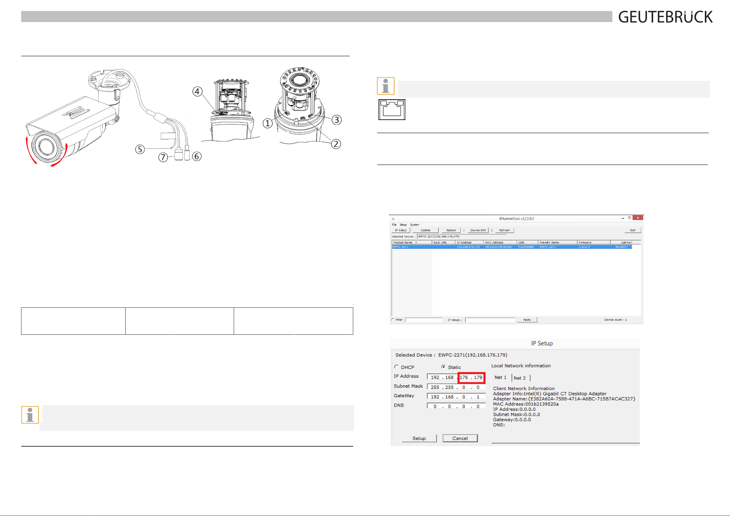
Camera’s Connectors
① Video Out Cable socket
Socket for the video output cable included in the package (CVBS: 1.0Vp-p / 75Ω BNC)
② PAL/NTSC button
Pressing the PAL/NTSC button each time changes the mode as follows.
No video output -> PAL-> NTSC*
* Steady output of video until you change the video output mode by pressing the button.
③
Reset button
Use the button to restart the device or to reset it to Factory Default.
④
microSD memory card slot
Camera supports up to 32GB. A card with Class 4 and higher is recommended for HD recordings.
⑤
Terminal Connector
Connector for cables of digital input/output and audio input/output. * **
Audio
connection
Black: AUD IN
Brown: AUD GND
Red: AUD OUT
Sensor (DI)
connection
Orange: DI
Yellow: DI COM
Alarm (DO)
connection
Green: DO1 (N.O)
Blue: DO1 COM
⑥
Power Adaptor Connector
Use DC12V for the power supply.
⑦
LAN connector
RJ45 LAN connector for 10/100 Base-T Ethernet (PoE supported).
*
Listen only is supported by GEUTEBRÜCK DVRs!
**Do NOT connect external power supply to the alarm I/O connector of the IP camera.
NOTE: It is not recommended to record with the microSD card for 24/7 continuously, as it may not be able to
support long term continuous data read/write. Please contact the manufacturer of the microSD card for
information regarding the reliability and the life expectancy.
Camera Cabling
Please follow the instructions below for cable connections and configuration.
Power Connection
Please use a DC 12V power adaptor and plug it to the camera and the power outlet. Alternatively, connect the ethernet
cable to the camera’s RJ-45 port and plug the other end of the cable into a PoE switch (IEEE 802.3af, 15.4 W).
NOTE: If PoE is used, make sure PSE is in used in the network.
Ethernet Cable Connection
Connect one end of the Ethernet cable to the RJ-45 connector of the camera, and plug the other end of the cable to
the network switch or PC.
NOTE: In some cases, Ethernet crossover cable might be needed when connecting the camera directly to the
PC.
Green Link Light indicates good network connection.
Orange Activity Light flashes for network activity indication.
Set up network environment
Be sure that the device and PC are on a same area network before running the installation.
User name: root Password: admin
Custom IP Environment
IPAdminTool is provided on attached CDRom.
IPAdminTool is a management tool, which automatically scans all of the network products for users to perform
administrative tasks, which includes network configurations, firmware update, device reboot, and device organizations.
To modify the device’s default IP address for customized network area:
1. Find the device from the IPAdminTool’s list and highlight the device’s name.
2. Right-click the mouse and select “IP Address”; IP Setup window appears.
3. In the IP Setup’s window, information under ‘Local Network information’ displays the user/PC’s network area
information. Those information need to be incorporated to the IP Address, Subnet Mask, Gateway, and DNS boxes,
except the last 2 sets of IP Address, which are to be the unique numbers for the device. Refer to the image above
for
the setting
2
1


