Geutebruck G-Cam/EHC-4781 User manual

G-Cam/EHC-4781/4888
Panorama 360° IP-Kamera
Installation / EN

2
Preface
The information given in this manual was current when published. The company reserves the right
to revise and improve its products. All specifications are subject to change without notice.
Copyright
Under copyright laws,the contents of this user manual may not be copied,photocopied,
translated,
reproduced
orreducedtoanyelectronicmediumor
machine-readable
format,
in whole or in part, without prior written permission of the company.
© 2017 by GEUTEBRÜCK All Rights preserved.
Notice
Mounting instructions for Cameras especially for Pole Mount.
Please note that the place of mounting should be stiff enough to counter strong wind
or other vibrations!
Otherwise all VCA functions like Motion Detection, Privacy Masking, etc. either in
cameras or with DVRs could be disturbed heavily and can cause unliked and often
alarms.
In some cases, mechanical problems or defects can be the result of such vibrations,
like overheating of focus motors caused by persistent mast shaking!
This manual provides the installation information for the Camera. To work with the
Cameras, any installer or technician must have the following minimum qualifications:
⚫A basic knowledge of CCTV systems and components
⚫A basic knowledge of electrical wiring and low-voltage electrical hookups
⚫A basic knowledge of network system setting
⚫Have read this manual completely
Important Information
Before proceeding, please read and observe all instructions and warnings in this manual.
Retain this manual with the original bill of sale for future reference and, if necessary,
warranty service. When unpacking the unit, check for missing or damaged items. If any
item is missing, or if damage is evident, DO NOT INSTALL OR OPERATE THIS
PRODUCT. Contact the dealer for assistance.
3
Regulation
This device complies with Part 15 of the FCC Rules. Operation is subject to
the following two conditions: (1) This device may not cause harmful
interference, and (2) this device must accept any interference received,
including interference that may cause undesired operation.
This symbol on the product or on its packaging indicates that this product
shall not be treated as household waste in accordance with Directive 2002 /
96 / EC. Instead it shall be handed over to the applicable collection point for
the recycling of electrical and electronic equipment. By proper waste
handling of this product, please ensure thatithasnonegativeconsequences
for the environment and human health, which could otherwise be caused if
this product is thrown into the garbage bin. The recycling of materials will
help to conserve natural resources.
For more details information about recycling of this product, please contact
the local city office, household waste disposal service or the shop which
purchased the product.
Compliance is evidenced by written declaration from our suppliers,
assuring that any potential trace contamination levels of restricted
substances are below the maximum level set by EU Directive 2002
/ 95 / EC, or are exempted due to their application.

4
Warnings and Cautions
Handle the camera carefully
Do not abuse the camera. Avoid striking, shaking, etc. The camera could be damaged by
improper handing or storage.
⚫Installing electricity wiring carefully
Ask qualified personnel of electrical wiring for the installation.
The camera is capable of surge protection; ensure AC power model units grounded
appropriately against damage of heavy current or electric shock.
⚫Do not disassemble the camera
To prevent electric shock, do not remove screws or covers. There are no user serviceable
parts inside. Ask a qualified service person for servicing.
⚫Do not operate the camera beyond the specified temperature, humidity or
power source ratings
⚫Do not use strong or abrasive detergents when cleaning the camera body
Use a dry cloth to clean the camera when it is dirty. In case the dirt is hard to remove, use a
mild detergent and wipe the camera gently.
⚫Never face the camera towards the sun
Do not aim the camera at bright objects. Whether the camera is in use or not, never aim it at
thesunor other extremelybrightobjects.Otherwise,the cameramaybe smearedor damaged.
Mounting instructions for Cameras especially for Pole Mount.
Please note that the place of mounting should be stiff enough to counter strong wind
or other vibrations!
Otherwise all VCA functions like Motion Detection, Privacy Masking, etc. either in cameras or
with DVRs could be disturbed heavily and can cause unliked and often alarms.
In some cases, mechanical problems or defects can be the result of such vibrations, like
overheating of focus motors caused by persistant mast shaking!

5
Table of Contents
Preface................................................................................................................................................2
Regulation............................................................................................................................................3
Warnings and Cautions........................................................................................................................4
1. Overview.......................................................................................................................................6
1.1. Features ................................................................................................................................6
1.2. Package Contents .................................................................................................................7
1.3. Connectors (Indoor only) .......................................................................................................8
1.4. Function Cables ( Outdoor only)............................................................................................9
2. Camera Cabling..........................................................................................................................10
2.1. Power Connection ...............................................................................................................10
2.2. Ethernet Cable Connection..................................................................................................10
2.3. Connect Alarm I/O...............................................................................................................10
2.4. Camera Installation..............................................................................................................11
3. System Requirements.................................................................................................................12
4. Access Camera ..........................................................................................................................13
5. Setup Video Resolution ..............................................................................................................17
6. Configuration Files Export / Import..............................................................................................18
7. Tech Support Information............................................................................................................18
7.1. Delete the Existing DCViewer..............................................................................................18
7.2. Setup Internet Security ........................................................................................................19

6
1. Overview
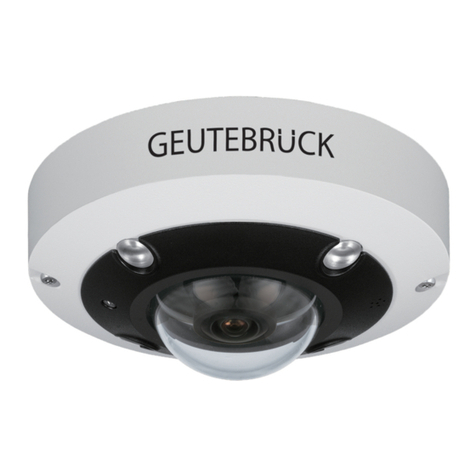
The DNN Network Fisheye IP Camera is a high performance surveillance solution features 360° wide
coverage without blind spots. The fisheye camera supports up to 12 Megapixels resolution streaming
and maintains at 20fps that allows the video stream can be viewed smoothly. Moreover, the fisheye
camera supports various view mode (digital PTZ, panoramic view, etc.) which allows users to choose
based on their own preference. The DNN Fisheye IP Camera is suitable to apply in wide open space
environments like office rooms, hotel lobby, apartment front door, etc.
In addition, the embedded edge dewarping engine enables the fisheye camera to dewarp images by
camera itself rather than consuming resources from the backend devices. The camera also includes
IR LED module and Smart Picture/Quality/Noise Reduction features that improves the image quality
in low light environment.
1.1. Features
▪Progressive Scan CMOS Image Sensor Support Up to 12M Resolution
▪Edge Dewarping/ Backend Dewarping
▪Multi Codec Support (H.265 / H.264 / MJPEG)
▪Multiple Dewarp Display Modes Digital PTZ / Panorama View / Quad View
▪True Day/Night Function (ICR)
▪IR LED (Working Distance Up to 5m)
▪3D Motion Compensated Noise Reduction
▪Smart Event Function: External Input/ Motion Detection/ Network Failure Detection/ Tampering
Alarm/ Periodical Event/ Manual Trigger/ Audio Detection
▪Micro SD/ SDHC/ SDXC Card Support
▪ONVIF Profile S/ G/ Q/ T Support
▪Weatherproof (IP66) -Outdoor only
▪IK10

7
1.2. Package Contents
Please check the package containing the following items listed below.
DNN IR Fisheye
IP Camera
Self-Tapping Screw (x3)
Plastic Anchor (x3)
Security Torx
Quick Guide
NOTE: The supplied self-tapping screws are for soft substances / materials such as wood.
For other installation environments such as cement wall, users MUST pre-drill and use
plastic anchors before fastening the supplied self-tapping screws on the wall.
NOTE: To use an external power supply, please contact your supplier to confirm that the
power supply complies with the LPS requirements and shares the same power
specifications with the camera.
NOTE: Do not replace batteries of the camera. Risk of explosion may occur if the battery is
replaced by an incorrect type.

8
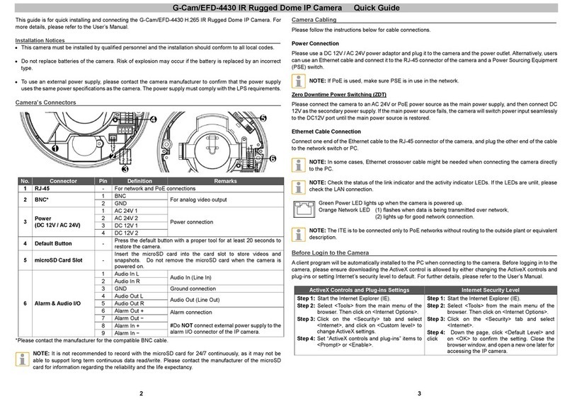
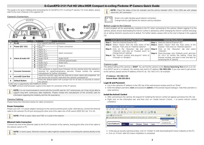
1.3. Connectors (Indoor only)
Please loosen the security screws and open the cover to reach the connectors.
The diagram below shows the connectors of the camera. Definition for each connector is given as
follows.
No.
Connector
Pin
Definition
Remarks
1
RJ-45
-
For network and PoE connections
2
Power (DC 12V)
1
DC 12V –
Power connection
2
DC 12V +
3
microSD Card Slot
-
Insert the microSD card into the card slot to store
videos and snapshots. Do not remove the
microSD card when the camera is powered on.
4
Alarm & Audio I/O*
1
Alarm Out +
Alarm connection
* Do NOT connect
external power supply to
the alarm I/O connector of
the camera.
2
Alarm Out -
3
Alarm In +
4
Alarm In -
5
GND
Ground connection
6
Audio Out (Line out)
Two-way audio
transmission
7
Audio In (Line in)
5
Built-in Microphone
-
Audio In
6
Default Button
-
Press the button with a proper tool for at least 20
seconds to restore the system.
7
Built-in Speaker
-
Audio Out

9
NOTE: To avoid audio quality degradation, do NOT connect built-in microphone and
external audio-input device (via Line-in) at the same time. So does the audio-output
connection.
NOTE: It is not recommended to record with the microSD card for 24/7 continuously, as it
may not be able to support long term continuous data read/write. Please contact the
manufacturer of the microSD card for information regarding the reliability and the life
expectancy.
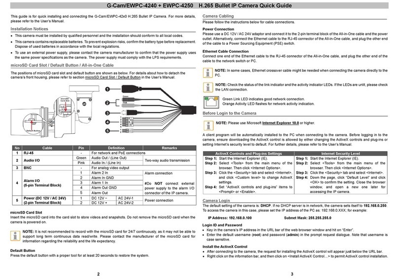
1.4. Function Cables ( Outdoor only)
No.
Connector
Pin
Definition
Remarks
1
Audio I/O
Pink
Audio In (Line in)
Two-way audio
transmission
Green
Audio Out (Line out)
2
Power (DC 12V)
(2-Pin Terminal Block)
Black
DC 12V –
Power connection
Red
DC 12V +
3
Alarm I/O
(4-Pin Terminal Block)
1
Alarm In –
Alarm connection
* Do NOT connect
external power supply
to the alarm I/O
connector of the
camera.
2
Alarm In +
3
Alarm Out –
4
Alarm Out +
4
RJ-45
-
For network and PoE connections
-
Default Button
-
Refer to the Default Button in the table under
Connectors (Indoor Only).
-
microSD Card Slot
-
Refer to the microSD Card Slot in the table
under Connectors (Indoor Only).

10
2. Camera Cabling
Please follow the instructions below to complete the cable connections.
NOTE: This camera must be installed by qualified personnel and the installation should
conform to all local codes.
2.1. Power Connection
For power connection, please refer to section Connectors for the Indoor models, and see section All
in One Cable for the Outdoor models. Alternatively, users can power the camera by PoE if a Power
Sourcing Equipment (PSE) switch is available. Refer to the section below for Ethernet cable
connection.
NOTE: If the device is powered over Ethernet, make sure the PSE is connected to the
network.
2.2. Ethernet Cable Connection
To have best transmission quality, cable length shall not exceed 100 meters. Connect one end of the
Ethernet cable to the RJ-45 connector of the camera and plug the other end of the cable to the
network switch or PC.
NOTE: In some cases, Ethernet crossover cable might be needed when connecting the
camera directly to the PC.
Check the status of the link indicator and the activity indicator LEDs. If the LEDs are unlit, please
check the LAN connection.
Green Link Light indicates good network connection.
Orange Activity Light flashes for network activity indication.
2.3. Connect Alarm I/O
The camera supports one alarm input and one relay output for alarm application. Refer to section
Connectors for pin definitions.
NOTE: Do NOT connect external power supply to the alarm I/O connector of the IP
camera.

11
2.4. Camera Installation
The following description demonstrates how to directly install the camera to the ceiling or to the wall.
Step 1:
Loosen the two security screws on the camera with the supplied
security torx and open the dome cover.
Step 2:
Place the camera at the installation location. Mark the position of
the two screw holes indicated in the right figure on the ceiling/wall.
Then draw a line along the concave edge of the camera to indicate
the cable position.
Step 3:
On the ceiling/wall, draw a dot 20mm above the center of the
marked concave edge. Set the marked dot as the center, draw a
cable entry hole with 30mm diameter (radius as 15mm) and drill
the cable entry hole.

12
Step 4:
Drill a hole slightly smaller than the supplied plastic screw anchor on each marked screw hole. Then
insert the plastic screw anchors into the drilled holes.
Step 5:
Thread the cables through the cable entry hole. Match the two screw holes on the camera with the
plastic screw anchors at the installation location. Fasten the camera with the supplied self-tapping
screws.
Step 6:
Attach the dome cover to the camera and fasten the two security screws.
3. System Requirements
To perform the IP camera via web browser, please ensure the PC is in good network connection, and
meet system requirements as described below.
Items
System Requirement
Personal Computer
Minimum :
1. Intel®Core™ i5-2430M @ 2.4 GHz
2. 4 GB RAM
Operating System
Windows 7 or later operating system
Web Browser
Microsoft Internet Explorer 11.0 (recommended)
Chrome
Firefox
Safari
Network Card
10Base-T (10 Mbps), 100Base-TX (100 Mbps) or
1000Base-T operation
Viewer
ActiveX control plug-in for Microsoft IE
NOTE: The ITE is to be connected only to PoE networks without routing to the “outside
plant”or equivalent description. More information of “outside plant” see Wikipedia.

13
4. Access Camera
For initial access to the IP camera, users can search the camera through the installer program:
DeviceSearch.exe.
Accessing the Camera by Device Search Software
▪Step 1: Double click on the program Device Search.exe.
▪Step 2: After its window appears, click on the <Device Search> button on the top. All the
finding IP devices will be listed in the page.
▪Step 3: Find the camera in the list by its IP address and click on it. The default IP address of
the camera is: 192.168.0.250.
▪Step 4: The default IP address of the camera may not be in the same LAN as the IP address of
the PC. If so, the IP address of the camera needs to be changed. Right click on the camera and
click <Network Setup>. Meanwhile, record the MAC address of the camera, for future
identification.
▪Step 5: The <Network Setup> page will come out. Select <DHCP> and click <Apply> down the
page. The camera will be assigned with a new IP address.
▪Step 6: Click <OK> on the Note of setting change. Wait for one minute to re-search the
camera.
▪Step 7: Click on the <Device Search> button to re-search all the devices. Find the camera in
the list by its MAC address. Then double click or right click and select <Browse> to access the
camera directly via a web browser.
▪Step 8: A prompt window requesting for default username and password will appear. Enter the
default username and password shown below to login to the camera.
Login ID
Password
root
admin
NOTE: ID and password are case sensitive.
NOTE: It is strongly advised that administrator’s password be altered for the security
concerns.

14
Installing DCViewer Software Online
For initial access to the camera, a client program, DCViewer, will be automatically installed to the PC
when connecting to the camera.
If the web browser doesn’t allow DCViewer installation, please check the Internet security settings or
ActiveX controls and plug-ins settings (refer to section Setup Internet Security) to continue the
process.
The Information Bar (just below the URL bar) may come out and ask for permission to install the
ActiveX Control for displaying video in browser. Right click on the Information Bar and select <Install
ActiveX Control…> to allow the installation.
The download procedure of DCViewer software is specified as follows.
▪Step 1: In the DCViewer installation window, click on <Next> to start installation.
▪Step 2: The status bar will show the installation progress. After the installation is completed,
click on <Finish> to exit the installation process.
▪Step 3: Click on <Finish> to close the DCViewer installation page.
Once the Viewer is successfully installed, the Home page of the IP camera will be shown as the figure
below.

15
Ceiling Mount Installed Camera
NOTE: For more details about the function buttons on the Home page, please refer to the
Webbrowser Menu.

16
Wall Mount Installed Camera
NOTE: For more details about the function buttons on the Home page, please refer to the
Webbrowser Menu.

17
5. Setup Video Resolution
Users can setup video resolution on Video Configuration page of the user-friendly browser-based
configuration interface.
Video Configuration can be found under this path: Streaming> Video Configuration.
The default video resolution of 6M and 12M models are shown as below. The default resolution varies
with different Fisheye Dewarping types, Front End Camera Dewarping and Back End Software
Dewarping.
Users can setup the Fisheye Dewarping types on Camera setting page. Click on <Fisheye Setting>
on Camera setting page and choose a fisheye dewarping type for correcting the fisheye source
images. Then, select the camera’s installation method to view the dewarped images with the correct
viewing modes.
4M Front End
H.264- 2048 x 2048 (25 fps)
12M Back End
H.264- 4000 x 3000 (20 fps)

18
6. Configuration Files Export / Import
To export / import configuration files, users can access the Maintenance page on the user-friendly
browser-based configuration interface.
The Maintenance setting can be found under this path: System> File Import/Export.
Users can export configuration files to a specified location and retrieve data by uploading an existing
configuration file to the camera.
Export Files
Users can save the system settings by exporting the configuration file (.bin) to a specified location for
future use. Click on the <Export> button, and the popup File Download window will come out. Click on
<Save> and specify a desired location for saving the configuration file.
Upload Files
To upload a configuration file to the camera, click on <Browse> to select the configuration file, and
then click on the <Upload> button for uploading.
7. Tech Support Information
This chapter will introduce how to delete previously-installed Viewer in the PC and how to setup the
Internet security.
7.1. Delete the Existing DCViewer
For users who have installed the DCViewer in the PC previously, please remove the existing
DCViewer from the PC before accessing to the IP camera.
Deleting the DCViewer
In the Windows <Start Menu>, activate <Control Panel>, and then double click on <Add or Remove
Programs>. In the <Currently installed programs> list, select <DCViewer> and click on the button
<Remove> to uninstall the existing DCViewer.
Deleting Temporary Internet Files
To improve browser performance, it is suggested to clean up all the files in the <Temporary Internet
Files>. The procedure is as follows.
▪Step 1: In the web browser, clicks on the <Tools> tab on the menu bar and select <Internet
Options>.

19
▪Step 2: Click on the <Delete> button under <Browsing History> section. In the appeared
window, tick the box beside the <Temporary Internet files>.
▪Step 3: Click on <Delete> to start deleting the files.
7.2. Setup Internet Security
If ActiveX control installation is blocked, please either set Internet security level to default or change
ActiveX controls and plug-ins settings.
Internet Security Level: Default
▪Step 1: Start the Internet Explorer (IE).
▪Step 2: Click on the <Tools> tab on the menu bar and select <Internet Options>.
▪Step 3: Click on the <Security> tab, and select <Internet> zone.
▪Step 4: Down the page, click on the <Default Level> button and click on <OK> to confirm the
setting. Close the browser window, and restart a new one later to access the camera.
ActiveX Controls and Plug-ins Settings
▪Step 1: Repeat Step 1 to Step 3 of the previous section above.
▪Step 2: Down the page, click on the <Custom Level> button to change ActiveX controls and
plug-ins settings. The Security Settings window will pop up.
▪Step 3: Under <ActiveX controls and plug-ins>, set ALL items (as listed below) to <Enable> or
<Prompt>. Please note that the items vary by IE version.
ActiveX controls and plug-ins settings:
1. Binary and script behaviors.
2. Download signed ActiveX controls.
3. Download unsigned ActiveX controls.
4. Allow previously unused ActiveX controls to run without prompt.
5. Allow Scriptlets.
6. Automatic prompting for ActiveX controls.
7. Initialize and script ActiveX controls not marked as safe for scripting.
8. Run ActiveX controls and plug-ins.
9. Only allow approved domains to use ActiveX without prompt.
10. Script ActiveX controls marked safe for scripting*.
11. Display video and animation on a webpage that does not use external media player.

20
▪Step 4: Click on <OK> to accept the settings. A prompt window will appear for confirming the
setting changes, click <Yes(Y)> to close the Security Setting window.
▪Step 5: Click on <OK> to close the Internet Options screen.
▪Step 6: Close the browser window and restart a new one later to access the camera.
Other manuals for G-Cam/EHC-4781
1
This manual suits for next models
3
Table of contents
Other Geutebruck IP Camera manuals

Geutebruck
Geutebruck G-Cam/EBC-3140 User manual

Geutebruck
Geutebruck G-Cam/EWPC-2271 User manual

Geutebruck
Geutebruck G-Cam/EWPC-2275 User manual

Geutebruck
Geutebruck G-Cam/EHC-4781 User manual

Geutebruck
Geutebruck G-Cam/ESD-4630 User manual

Geutebruck
Geutebruck G-Cam/EWPC-4240 User manual

Geutebruck
Geutebruck G-Cam/EFD-3261 User manual

Geutebruck
Geutebruck G-Cam/EFD-3131 User manual

Geutebruck
Geutebruck G-Cam User manual

Geutebruck
Geutebruck GWPC-103/DN-IR User manual