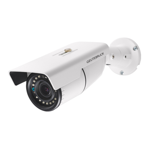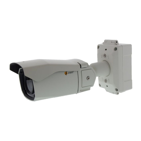
G-Cam/EWPC-2275
Full
HD
IR Bullet
IP
Camera
Quick
Guide
3. The system’s default web browser opens the device’s address.
Whether directly accessing the streaming video through typing IP address on a web page or taking steps
through IPAdminTool, the ActiveX is needed to be installed for the Microsoft® Internet Explorer to have the
complete configuration privileges.
NOTE: For details about configuring the camera in GEUTEBRÜCK-Software (G-Set and GSC-Setup),
please refer to the Quick Guides, which can be found on the supplied CD ROM
Reset of the Camera
Camera
1. While the device is in use, press the Reset button.
2. Wait for the system to reboot.
Do not press the reset button longer than 2 seconds, otherwise the camera may be switched to its factory
default settings.
Webpage
1. Go to Setup > Maintenance > Reboot.
2. Click Reboot. A dialog box opens to ask you if you really want to reboot.
3. Click OK, and wait for the system to complete booting.
NOTE: In both cases it may come to a timeout. Refresh the homepage by pressing F5 button or the refresh
icon in the IE´s input box.
Factory Default
When reset the device to the factory default setting, all parameters including the IP address will be initialized.
1. While the device is in use, press the Reset button for 10 seconds.
2. Wait for the system to reboot.
The factory default settings are described as below:
IP address: 192.168.xxx.yyy
Network mask: 255.255.0.0
Gateway: 192.168.0.1
User ID: root
Password: admin
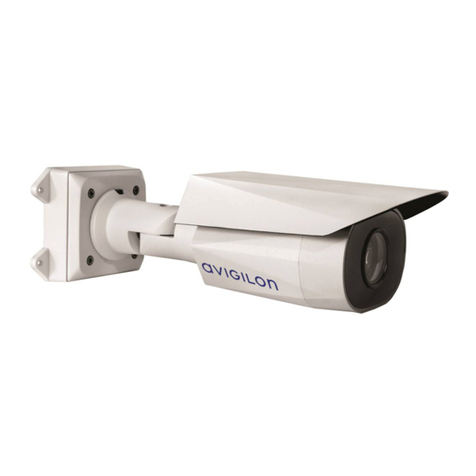
This guide is for quick installing and connecting the G-Cam/EWPC-2275 Bullet IP camera. For more details, please
refer to the User’s Manual in the supplied CDROM.
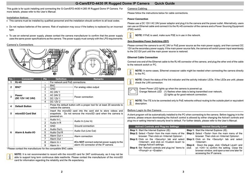
Camera’s Connectors
① Video Out Cable socket
Socket for the video output cable included in the package (CVBS: 1.0Vp-p / 75Ω BNC)
② PAL/NTSC button
Pressing the PAL/NTSC button each time changes the mode as follows.
No video output -> PAL-> NTSC*
* Steady output of video until you change the video output mode by pressing the button.
③ Reset button
Use the button to restart the device or to reset it to Factory Default.
④ microSD memory card slot
Camera supports up to 32GB. A card with Class 4 and higher is recommended for HD recordings.
⑤ Terminal Connector
Connector for cables of digital input/output and audio input/output. * **
Audio
connection
Black: AUD IN
Brown: AUD GND
Red: AUD OUT
Sensor (DI)
connection
Orange: DI
Yellow: DI COM Alarm (DO)
connection
Green: DO1 (N.O)
Blue: DO1 COM
⑥ Power Adaptor Connector
Use DC12V for the power supply.
⑦ LAN connector
RJ45 LAN connector for 10/100 Base-T Ethernet (PoE supported).
*Listen only is supported by GEUTEBRÜCK DVRs!
**Do NOT connect external power supply to the alarm I/O connector of the IP camera.
NOTE: It is not recommended to record with the microSD card for 24/7 continuously, as it may not be able to
support long term continuous data read/write. Please contact the manufacturer of the microSD card for
information regarding the reliability and the life expectancy.
Camera Cabling
Please follow the instructions below for cable connections and configuration.
Power Connection
Please use a DC 12V power adaptor and plug it to the camera and the power outlet. Alternatively, connect the ethernet
cable to the camera’s RJ-45 port and plug the other end of the cable into a PoE switch (IEEE 802.3af, 15.4 W).
4 1
