GEZE Boxer User manual

GEZE
E-Gleitschiene
Boxer
DE Boxer Gleitschiene
mit elektrischer Feststellung
GB Boxer guide rail
with electrical hold-open device
FR Boxer bras à coulisse
avec arrêt électrique
119 6 4 4 - 0 3
DE Montageanleitung
GB Installation instructions
FR Instruction de montage

E-Gleitschiene Boxer
DE 2
Zu diesem Dokument
1 Zu diesem Dokument
Diese Anleitung beschreibt die Montage und den Anschluss sowie die Inbetriebnahme der GEZE Boxer E-Gleit-
schiene.
Verwendung mit:
àGeze Boxer Gr. 2-4
àGeze Boxer Gr. 3-6
Türönungswinkel: ca. 120°.
1.1 Produktbeschreibung
Diese Gleitschiene ist für die Montage an einügeligen Feuer- und Rauchschutztüren zugelassen. Die Anlage
enthält eine elektrische Feststellung für den Türügel.
Bei Stromunterbrechung löst die elektrische Feststellung
aus und die Tür schließt selbsttätig.
1.2 Weitere Dokumente
Im Lieferumfang der Komponenten sind jeweils weitere Unterlagen zur Montage bzw. zum Anschluss der Anlage
enthalten. Bitte diese zu beachten.
Montage der Schließer, siehe Montageanleitung Boxer.
2 Symbole und Darstellungsmittel
Warnhinweise
In dieser Anleitung werden Warnhinweise verwendet, um Sie vor Sach- und Personenschäden zu warnen.
XLesen und beachten Sie diese Warnhinweise immer.
XBefolgen Sie alle Maßnahmen, die mit dem Warnsymbol und Warnwort gekennzeichnet sind.
Warnsymbol Warnwort Bedeutung
GEFAHR Gefahren für Personen.
Nichtbeachtung führt zu Tod oder schweren Verletzungen.
– VORSICHT Informationen zur Vermeidung von Sachschäden, zum Verständnis oder zum Optimie-
ren der Arbeitsabläufe.
Weitere Symbole und Darstellungsmittel
Um die korrekte Bedienung zu verdeutlichen, sind wichtige Informationen und technische Hinweise besonders
herausgestellt.
Symbol Bedeutung
bedeutet „Wichtiger Hinweis“
bedeutet „Zusätzliche Information“
XSymbol für eine Handlung: Hier müssen Sie etwas tun.
XHalten Sie bei mehreren Handlungsschritten die Reihenfolge ein.
3 Produkthaftung
Gemäß der im Produkthaftungsgesetz denierten Haftung des Herstellers für seine Produkte sind die in dieser
Broschüre enthaltenen Informationen zu beachten. Die Nichtbeachtung entbindet den Hersteller von seiner
Haftungspicht.
4 Sicherheitshinweise
àMontage, Inbetriebnahme und Reparaturen sind durch einen Fachbetrieb auszuführen.
àNur GEZE Originalteile für Reparaturarbeiten verwenden.
àEigenmächtige Veränderungen an der Anlage schließen eine Haftung von GEZE für daraus resultierende Schäden aus.
àBei Anwendung an Feuer- und Rauchschutzabschlüssen sind die länderspezischen Vorschriften zu beachten.
àFür den elektrischen Anschluss und die Inbetriebnahme das Dokument „Anleitung zur Montage, Inbetrieb-
nahme, Bedienung und Wartung der GEZE Feststellanlage FA GC“ beachten.
àMax. Türönungswinkel mit Türstopper begrenzen.

E-Gleitschien Boxer
DE 3
Lieferumfang
5 Lieferumfang
Abb.: 5.1
1 E-Gleitschiene Boxer
2 Gleithebel
3 Gleitstein
4 Endkappen
5 Elektrische-Feststellung
Schrauben und Zubehörbeutel (ohne Abbildung)
6 Montage, Befestigung
6.1 Montagevorbereitung
Rahmenbearbeitung Unterputz-Stromzuführung 24V Anschluss
86,5
459
125 380
±0,2
Ø16
31,5
26
R8
95
85,5
457
440
107,8
103,2 249,8
240
175
7,5
4,5
26 14
30
4
60
51
35
A-A
A
A
Türügelbearbeitung GEZE Boxer Gr. 3-6/Gr. 2-4
334
510
320
79
82
9
20
40,5
32,5
9
R8
35
R8
94,5
99
69
72
354
340
293
286
30
38,5
31
40
32
51
42
54
45
Rahmen- und Türügelbearbeitung für Rechtsügel spiegelbildlich. Maße in
für GEZE Boxer Gr. 2-4
Abb.: 6.1.1
XTür gemäß Abb. 6.1.1 vorbereiten.
XBoxer nach Anleitung montieren und das Schließzeitventil schließen.
Auf Anfrage stellt GEZE für die gängigen Türprole Einbauzeichnungen zur Verfügung.
Für den Fall, dass dieses Produkt in einer Feststellanlage zum Einsatz kommt beachten Sie bitte auch das Doku-
ment„Anleitung zur Montage, Inbetriebnahme, Bedienung und Wartung der GEZE Feststellanlage FA GC“.

E-Gleitschiene Boxer
DE 4
Montage, Befestigung
6.2 Gleitschiene montieren und 24 V Versorgungskabel anschließen
Rot =’+’ (Klemme 1)
Weiß = ’–’ (Klemme 2)
Abb.: 6.2.1
XGleitstein richtungsorientiert in Gleitschiene einführen (1.).
Der Kabelanschluss muss zur Bandseite zeigen.
XGleitschiene mit 2 Schrauben befestigen (2.) (Anzugsmoment: 2 Nm).
XBauseitiges 24 V Kabel an Lüsterklemme anklemmen (3.).
Elektrische Feststellung ist bestromt.
XLüsterklemme auf Endkappe aufstecken (4.).
XEndkappen auf Gleitschiene aufklipsen (5.).
XGleithebel mit Gleitstein verbinden (6.) (Anzugsmoment: 5 Nm).
Alle Schraubmomente sind ggf. bauseitig anzupassen.
6.3 Einstellen der elektrischen Feststellung
1.
Abb.: 6.3.1
XTürügel auf den gewünschten Feststellwinkel önen und festsetzen (1.).
XKabelschutzfolien aus der Gleitschiene entfernen (2.).
XKlemmschrauben der
elektrischen
Feststellung lösen (3.).
XElektrische
Feststellung verschieben, bis Rastkeil am Gleitstein anliegt (4.).
XElektrische
Feststellung festschrauben (5.).
XZur Vermeidung von Schlaufen, Kabel straen und Kabelschutz direkt am Ende der elektrischen Feststellung
anlegen (6.).
XLoses Kabel im Kabelschutz und freien Bereich verstauen (7.).
XSichtbares Kabel mit der Kabelschutzfolie xieren (8.).

E-Gleitschien Boxer
DE 5
Erstinbetriebnahme
VORSICHT!
XFreigängigkeit der Wippe nach oben prüfen!
Bei Bedarf kann die Haltekraft eingestellt werden (9.). Nach EN 1155 soll bei einer Tür mit 90°-Feststellung
das Ausrückmoment 40 Nm - 120 Nm betragen.
7 Erstinbetriebnahme
7.1 Ersteinschaltung, Test
XTürügel önen und in die elektrische Feststellung einrasten.
XStromzufuhr unterbrechen.
àDer Türügel schließt sich.
7.2 Abnahmeprüfung (nur bei Einsatz in einer Feststellanlage)
Nach dem betriebsfertigen Einbau der Anlage ist am Verwendungsort deren einwandfreie Funktion und vor-
schriftsmäßige Installation durch eine Abnahmeprüfung festzustellen. Abnahmeprüfung durch autorisiertes
Fachpersonal siehe
Dokument „Anleitung zur Montage, Inbetriebnahme, Bedienung und Wartung der GEZE Fest-
stellanlage FA GC“.
8 Wartung, Pege, Reparatur
Eine regelmäßige Wartung ist erforderlich. Für weitere Informationen beachten Sie bitte das Dokument „Anlei-
tung zur Montage, Inbetriebnahme, Bedienung und Wartung der GEZE Feststellanlage FA GC“.
9 Technische Daten
Technische Daten siehe Dokument „Anleitung zur Montage, Inbetriebnahme, Bedienung und Wartung der GEZE
Feststellanlage FA GC“.

E-Gleitschiene Boxer
About this document
1 About this document
These instructions describe the installation and commissioning of the GEZE Boxer E-guide rail.
In conjunction with:
àGeze Boxer size 2-4
àGeze Boxer size 3-6
Opening angle of doors: approx. 120°.
1.1 Product description
This guide rail is approved for installation on single leaf re and smoke protection doors. The system includes
an electrical hold-open device for the door leaf. In case of power interruption, the electrical hold-open device is
triggered and the door closes automatically.
1.2 Related documents
Additional documents for the installation and connection of the system are supplied with every component.
Please follow these instructions.
For mounting of the door closer, refer to the Boxer mounting instructions.
2 Key to symbols
Warning
In these instructions, warnings are used to warn against material damage and injuries.
XAlways read and observe these warnings.
XFollow all instructions marked with the warning symbol and the word WARNING.
Warning
symbol
Warning Meaning
DANGER Danger for people.
Non-observance can result in death or serious injuries.
– CAUTION Information to prevent damage to property and to understand and optimise workow.
Further symbols used in these instructions
Important information and technical notes are emphasised to illustrate the correct operation.
Symbol Meaning
means “Important note“
means “Additional information”
XSymbol for a user action. Here you have to take an action.
XObserve the sequence if there are several action steps.
3 Product liability
According to the denition of manufacturer‘s liability for his products in the Product Liability Act, the informati-
on contained in this brochure are to be followed. Ignoring this information absolves the manufacturer from his
liability.
4 Safety instructions
àInstallation, commissioning and repairs must be performed by a specialist.
àUse only GEZE original parts for repair work.
àUnauthorised modications of the system excludes GEZE from the liability for any resulting damage.
àWhen used in re and smoke barriers, all local regulations should be observed.
àPlease observe the document “Instructions for Installation, Commissioning, Operation and Maintenance of the
GEZE Hold-Open Device FA GC“.
àRestrict the opening angle of the doors by a door stopper.
GB 2

E-Gleitschiene Boxer Scope of delivery
5 Scope of delivery
Fig.: 5.1
1 E-guide rail Boxer
2 Sliding lever
3 Sliding block
4 End caps
5 Electrical hold-open device
Screws and accessories bag (without illustration)
6 Mounting and securing
6.1 Drilling template
Work on doorframe Under-plaster supply 24V connection
86,5
459
125 380
±0,2
Ø16
31,5
26
R8
95
85,5
457
440
107,8
103,2 249,8
240
175
7,5
4,5
26 14
30
4
60
51
35
A-A
A
A
Work on leaf GEZE Boxer size 3-6/size 2-4
334
510
320
79
82
9
20
40,5
32,5
9
R8
35
R8
94,5
99
69
72
354
340
293
286
30
38,5
31
40
32
51
42
54
45
Work on frame and leaf for right leaf, mirror image Dimensions in
for GEZE Boxer size 2-4
Fig.: 6.1.1
XPrepare the door as shown in g. 6.1.1.
XFit the Boxer and close the closing time valve.
On request, GEZE will provide installation drawings for most common door proles.
In case this product is in use with an hold-open device, please observe the document “Instructions for Installati-
on, Commissioning, Operation and Maintenance of the GEZE Hold-Open Device FA GC” as well.
GB 3

E-Gleitschiene Boxer
Mounting and securing
6.2 Mounting guide rail and connect 24V supply cable
Red =’+’ (terminal 1)
White = ’–’ (terminal 2)
Fig.: 6.2.1
XInsert the sliding pad into the guide rail, making sure it faces the right way
(1.).
Cable terminal must be on the hinge side.
XFasten guide rail with 2 screws (2.) (tightening torque: 2 Nm).
XConnect customer-side 24 V cable to terminal block (3.).
Electrical hold-open device is energised.
XPush terminal block onto end cap (4.).
XClip end caps onto guide rail (5.).
XConnect sliding lever to sliding block (6.) (tightening torque 5 Nm).
All screwing torques are to be adjusted on site, if necessary.
6.3 Adjusting electrical hold-open device
1.
Fig.: 6.3.1
XOpen door leaf to desired hold-open angle and x it there (1.).
XRemove cable protection foils from guide (2.).
XLoosen clamping screws of electrical hold-open device (3.).
XMove electrical hold-open device until catch contacts sliding block
(4.).
XScrew down electrical hold-open device securely
(5.).
XTo prevent loops from forming, tighten cable and fasten cable protection at hold open device end (6.).
XStow away (7.) loose cable in the cable protection and free area.
XSecure exposed cable with the cable protection lm (8.).
GB 4

E-Gleitschiene Boxer Initial operation
CAUTION!
XCheck free upward movement of the rocker!
If necessary, the holding force can be adjusted (9.). According to EN 1155, the release torque should
amount to 40 Nm - 120 Nm for a door with 90° hold-open angle.
7 Initial operation
7.1 First Operation and Function Test
XOpen door leaf and engage in electrical hold-open device.
XInterrupt power supply.
àThe door leaf closes.
7.2 Testing for acceptance (only for use in a hold-open device)
An acceptance test must be carried out in order to ascertain the correct function and installation according to
the regulations once the installation has been completed on site. Acceptance test to be performed by authorised
personnel; see “Instructions for Installation, Commissioning, Operation and Maintenance of the GEZE Hold-Open
Device FA GC”
.
8 Maintenance, servicing, repairs
Regular servicing has to be carried out.
For more information on this, please observe the document “Instructions
for Installation, Commissioning, Operation and Maintenance of the GEZE Hold-Open Device FA GC”.
9 Technical data
For technical data, please observe the document “Instructions for Installation, Commissioning, Operation and Main-
tenance of the GEZE Hold-Open Device FA GC”.
GB 5

E-Gleitschiene Boxer
FR 2
Concernant le présent document
1 Concernant le présent document
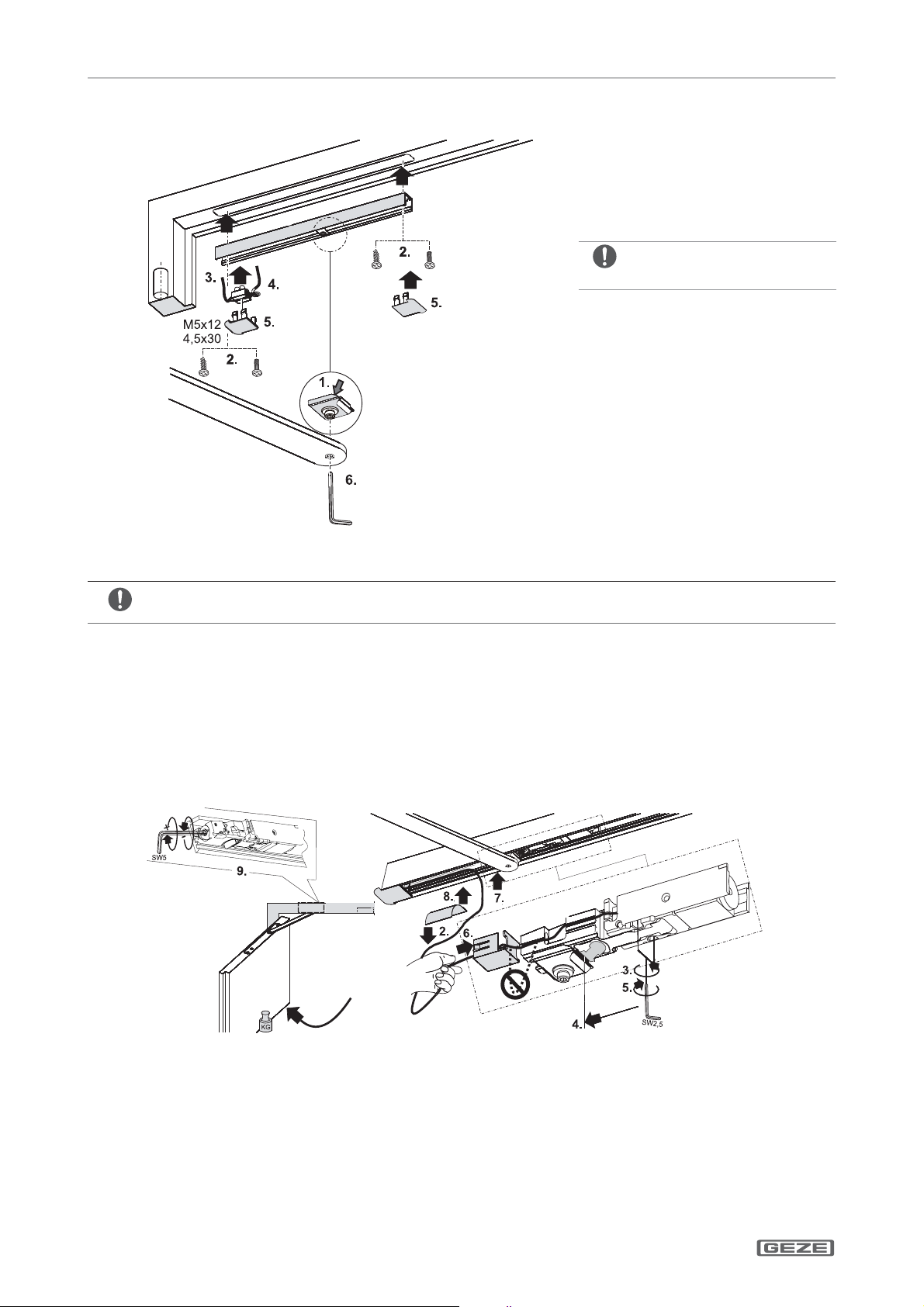
Le présent manuel décrit le montage et la mise en service ainsi que le raccordement du GEZE E-Bras à coulisse
Boxer.
Utilisation avec:
àGeze Boxer taille 2-4
àGeze Boxer taille 3-6
Angle d’ouverture : 120° max.
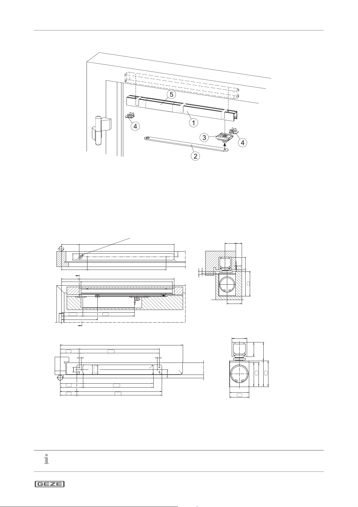
1.1 Description du produit
Cette glissière est homologuée pour être montée sur des portes anti-feu et anti-fumée à vantail unique. L‘installation
comprend un dispositif de blocage électrique pour le vantail. En cas d‘interruption de courant, le dispositif de blocage
électrique se déclenche et la porte se verrouille automatiquement.
1.2 Autres documents
L‘emballage contenant les composants comporte d‘autres documents pour le montage ou le branchement de
l‘installation. Il convient de les respecter. Pour montage du ferme porte, voir le
manuel Boxer
.
2 Symboles et moyens de représentation
Mises en garde
Ce manuel contient des mises en garde pour vous protéger des dommages personnels et matériels.
XLisez et observez toujours ces mises en garde.
XObservez toutes les mesures identiées par le symbole et le mot de mise en garde.
Symbole de
mise en garde
Mot de mise
en garde
Signication
DANGER Dangers pour les personnes.
Le non respect peut entraîner la mort ou des blessures graves.
– ATTENTION Informations destinées à éviter les dommages matériels, à une meilleure compréhensi-
on ou à l‘optimisation des processus de travail.
Autres symboles et moyens de représentation
Pour illustrer l‘utilisation correcte, les informations et consignes techniques importantes sont présentées de sorte à
attirer l‘attention.
Symbole Signication
signie « Remarque importante »
signie « Information complémentaire »
XSymbole pour une action : ici vous êtes invité à exécuter une action.
XLors de plusieurs étapes d‘action, respectez l‘ordre prescrit.
3 Responsabilité du produit
Conformément à la responsabilité du fabricant pour ses produits dénie dans la loi sur la responsabilité civile des pro-
duits, les informations contenues dans la présente brochure doivent être respectées. Le non-respect délie le fabricant
de son obligation de responsabilité.
4 Consignes de sécurité
àLe montage, la mise en service et les réparations doivent être eectués par une entreprise spécialisée.
àUtiliser uniquement des pièces GEZE d‘origine pour les travaux de réparation.
àToute modication du propre chef eectuée sur l‘installation exclut la responsabilité de GEZE pour les dommages en
résultant.
àIl convient de respecter les dispositions nationales en vigueur en cas d‘utilisation sur des portes anti-feu et anti-fumée.
àPour le raccordement électrique et la mise en service, observer les indications gurant dans le document « Instruc-
tions de montage, mise en service, utilisation et maintenance de l’installation de blocage GEZE FA GC ».
àLimiter l‘angle d‘ouverture en utilisant le stop-porte.

E-Gleitschiene Boxer
FR 3
Contenu de la livraison
5 Contenu de la livraison
Fig.: 5.1
1 Bras à coulisse
2 Levier coulissant
3 Coulisseau
4 Capuchons
5 Arrêt électrique
Vis de xation et sachet d‘accessoires (sans illustration)
6 Montage, xation
6.1 Gabarit de perçage
Traitement de cadre Alimentation du courant sous crèpi 24V raccordement
86,5
459
125 380
±0,2
Ø16
31,5
26
R8
95
85,5
457
440
107,8
103,2 249,8
240
175
7,5
4,5
26 14
30
4
60
51
35
A-A
A
A
Traitement de battant de porte GEZE Boxer taille 3-6/taille 2-4
334
510
320
79
82
9
20
40,5
32,5
9
R8
35
R8
94,5
99
69
72
354
340
293
286
30
38,5
31
40
32
51
42
54
45
Traitement de cadre et battant de porte pour battant mobile, gauche rééchi Dimensions
en pour GEZE Boxer Gr. 2-4
Fig.: 6.1.1
XPréparer le bloc porte conformément à la g. 6.1.1.
XMonter le ferme-porte boxer et fermer la vanne de temps de fermeture.
GEZE met à disposition sur simple demande les plans et notices de montage pour les prols de vantaux usuels.
En cas d’utilisation dans un dispositif de blocage, veuillez observer les indications gurant dans le document
« Instructions de montage, mise en service, utilisation et maintenance de l’installation de blocage GEZE FA GC ».

E-Gleitschiene Boxer
FR 4
Montage, xation
6.2 Monter les bras à coulisse et connecter 24 V câble d‘alimentation
Rouge =’+’ (borne 1)
Blanc = ’–’ (borne 2)
Fig.: 6.2.1
XIntroduire le coulisseau correctement orienté dans le bras à coulisse (1.).
Les câbles de connexion doivent être situés sur le côté des paumelles.
XFixer la glissière avec 2 vis (2.) (couple de serrage: 2 Nm).
XBrancher le câble 24 V côté bâtiment à la barrette de connexion (3.).
L‘arrêt électrique est sous tension.
XEncher la barrette de connexion sur le capuchon (4.).
XClipser les capuchons sur le bras à coulisse (5.).
XRelier le levier coulissant au coulisseau (6.) (couple de serrage: 5 Nm).
Tous les couples de serrage doivent être adaptés sur site.
6.3 Réglage des arrêts électriques
1.
Fig.: 6.3.1
XOuvrir le battant de porte à l‘angle d‘arrêt souhaité et le bloquer (1.).
XEnlever les lms protecteurs de câbles du bras à coulisse (2.).
XDesserrer les vis de serrage de l‘arrêt électrique (3.).
XDéplacer l‘arrêt électrique jusqu‘à ce que le coin de verrouillage repose contre le coulisseau
(4.).
XVisser l‘arrêt électrique
(5.).
XAn d‘éviter les boucles, tendre le câble et le placer le câble dans la protection à l‘extrémité de l‘arrêt (6.).
XRanger les câbles détachés dans la gaine de câbles et libres (7.).
XFixer le câble visible avec le lm de protection de câble (8.).

E-Gleitschiene Boxer
FR 5
Première mise en service
ATTENTION!
XVérier le libre fonctionnement de la bascule vers le haut!
La force de maintien peut être réglée selon besoin (9.). Selon EN 1155, le couple de débrayage d‘une porte avec
un blocage à 90° doit être de 40 Nm - 120 Nm.
7 Première mise en service
7.1 Première mise en service et essais fonctionnels
XOuvrir le battant et le verrouiller dans l‘arrêt électrique.
XCoupez la tension d‘alimentation.
àLe battant se ferme.
7.2 Contrôle de réception (uniquement en cas d’utilisation dans un dispositif de
blocage)
Après avoir monté l’installation, pour qu’elle puisse être mise en service, il faut constater sur le lieu d’utilisation
par un essai de réception, son bon fonctionnement et son installation réglementaire. Contrôle de réception par
un technicien qualiés agréé, voir document « Instructions de montage, mise en service, utilisation et mainte-
nance de l’installation de blocage GEZE FA GC ».
8 Maintenance, entretien, réparation
Il faut procéder à une maintenance régulière. Pour de plus amples informations, veuillez observer les indications
gurant dans le document « Instructions de montage, mise en service, utilisation et maintenance de l’installation
de blocage GEZE FA GC ».
9 Charactéristiques techniques
Pour les spécications techniques voir le document « Instructions de montage, mise en service, utilisation et
maintenance de l’installation de blocage GEZE FA GC ».

E-Gleitschiene Boxer
FR 6
Initial operation

E-ISM Boxer Notes/Notizen

Germany
GEZE GmbH
Niederlassung Süd-West
Tel. +49 (0) 7152 203 594
E-Mail: [email protected]
GEZE GmbH
Niederlassung Süd-Ost
Tel. +49 (0) 7152 203 6440
E-Mail: [email protected]
GEZE GmbH
Niederlassung Ost
Tel. +49 (0) 7152 203 6840
E-Mail: [email protected]
GEZE GmbH
Niederlassung Mitte/Luxemburg
Tel. +49 (0) 7152 203 6888
E-Mail: frankfurt.de@geze.com
GEZE GmbH
Niederlassung West
Tel. +49 (0) 7152 203 6770
E-Mail: [email protected]
GEZE GmbH
Niederlassung Nord
Tel. +49 (0) 7152 203 6600
E-Mail: hamburg.de@geze.com
GEZE Service GmbH
Tel. +49 (0) 1802 923392
E-Mail: service-[email protected]
Austria
GEZE Austria
E-Mail: [email protected]
www.geze.at
Baltic States
GEZE GmbH Baltic States oce
E-Mail: oce-[email protected]
www.geze.com
Benelux
GEZE Benelux B.V.
E-Mail: [email protected]om
www.geze.be
www.geze.nl
Bulgaria
GEZE Bulgaria - Trade
E-Mail: oce-[email protected]
www.geze.bg
China
GEZE Industries (Tianjin) Co., Ltd.
E-Mail: chinasales@geze.com.cn
www.geze.com.cn
GEZE Industries (Tianjin) Co., Ltd.
Branch Oce Shanghai
E-Mail: chinasales@geze.com.cn
www.geze.com.cn
GEZE Industries (Tianjin) Co., Ltd.
Branch Oce Guangzhou
E-Mail: chinasales@geze.com.cn
www.geze.com.cn
GEZE Industries (Tianjin) Co., Ltd.
Branch Oce Beijing
E-Mail: chinasales@geze.com.cn
www.geze.com.cn
France
GEZE France S.A.R.L.
E-Mail: fr[email protected]
www.geze.fr
Hungary
GEZE Hungary Kft.
E-Mail: oce-hungary@geze.com
www.geze.hu
Iberia
GEZE Iberia S.R.L.
E-Mail: info@geze.es
www.geze.es
India
GEZE India Private Ltd.
E-Mail: oce-in[email protected]
www.geze.in
Italy
GEZE Italia S.r.l
E-Mail: italia.it@geze.com
www.geze.it
GEZE Engineering Roma S.r.l
E-Mail: roma@geze.biz
www.geze.it
Poland
GEZE Polska Sp.z o.o.
E-Mail: [email protected]om
www.geze.pl
Romania
GEZE Romania S.R.L.
E-Mail: oce-ro[email protected]
www.geze.ro
Russia
OOO GEZE RUS
E-Mail: oce-russia@geze.com
www.geze.ru
Scandinavia – Sweden
GEZE Scandinavia AB
E-Mail: [email protected]om
www.geze.se
Scandinavia – Norway
GEZE Scandinavia AB avd. Norge
E-Mail: [email protected]
www.geze.no
Scandinavia – Denmark
GEZE Danmark
E-Mail: danmark.se@geze.com
www.geze.dk
Singapore
GEZE (Asia Pacic) Pte, Ltd.
E-Mail: [email protected]
www.geze.com
South Africa
GEZE Distributors (Pty) Ltd.
E-Mail: info@gezesa.co.za
www.geze.co.za
Switzerland
GEZE Schweiz AG
E-Mail: schweiz.ch@geze.com
www.geze.ch
Turkey
GEZE Kapı ve Pencere Sistemleri
E-Mail: oce[email protected]
www.geze.com
Ukraine
LLC GEZE Ukraine
E-Mail: oce-ukraine@geze.com
www.geze.ua
United Arab Emirates/GCC
GEZE Middle East
E-Mail: gezeme@geze.com
www.geze.ae
United Kingdom
GEZE UK Ltd.
E-Mail: [email protected]
www.geze.com
GEZE GmbH
Reinhold-Vöster-Straße 21–29
71229 Leonberg
Germany
Tel.: 0049 7152 203 0
Fax.: 0049 7152 203 310
www.geze.com
Table of contents
Languages:
Other GEZE Door Lock manuals