GEZE SecuLogic RWS TZ 300 Installation and operation manual

1
GEZE
SECULOGIC
TZ300
Emergency Exit System
Door Control Unit
EN Installation and Commissioning
Instructions with Wiring Diagram

SECULOGIC TZ300
2
Contents
1About this document ..........................................................................................................................................3
1.1 Product description......................................................................................................................................................................................3
1.2 Related documents.......................................................................................................................................................................................3
1.3 Key to symbols................................................................................................................................................................................................3
1.4 Abbreviations..................................................................................................................................................................................................4
2Safety and responsibility....................................................................................................................................5
2.1 General safety instructions .......................................................................................................................................................................5
2.2 Target readership and qualications......................................................................................................................................................5
2.3 Product liability..............................................................................................................................................................................................5
3Installation and assembly...................................................................................................................................6
3.1 Preconditions..................................................................................................................................................................................................6
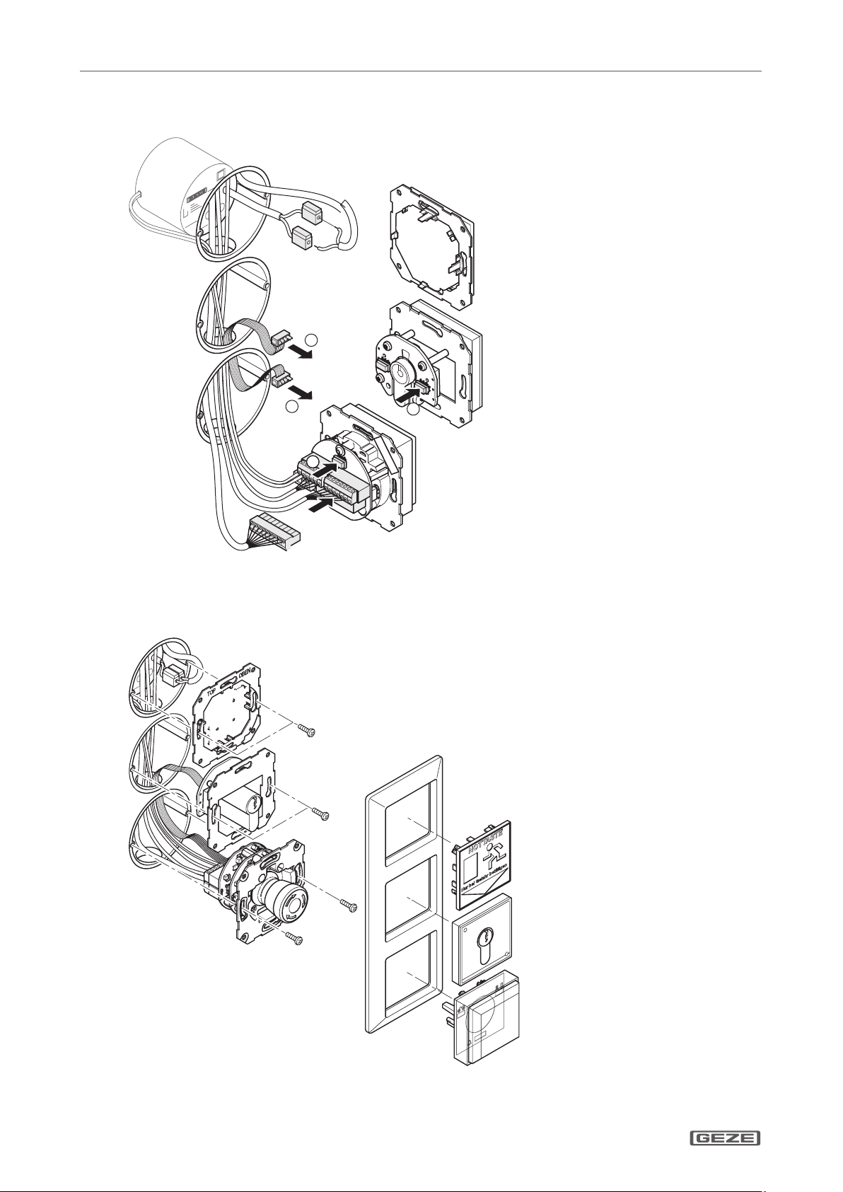
3.2 Installing the ush-mounted door control unit.................................................................................................................................6
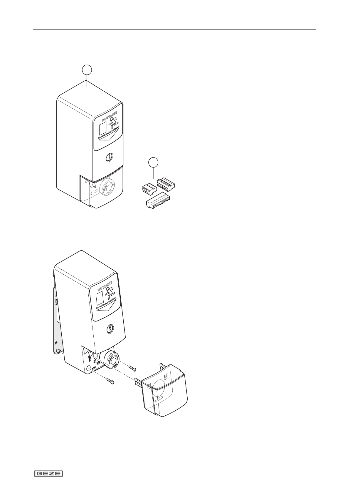
3.3 Fitting the surface-mounted door control unit .................................................................................................................................9
3.4 Replacing the lock cylinder .....................................................................................................................................................................11
3.5 Fitting a safety cylinder, length 40/10.................................................................................................................................................11
4Commissioning....................................................................................................................................................12
4.1 Preconditions ...............................................................................................................................................................................................12
4.2 Settings ..........................................................................................................................................................................................................12
4.3 Description of basic functions................................................................................................................................................................12
4.4 Fire detection system (BMA), hazard alert system (GMA), smoke and heat extraction system (RWA)........................13
5Operation...............................................................................................................................................................14
5.1 Controlling door control unit TZ300 with the key switch............................................................................................................15
5.2 Opening doors in emergencies and triggering alarm.................................................................................................................. 16
5.3 Cancelling alarms ........................................................................................................................................................................................17
5.4 Alarm signal...................................................................................................................................................................................................18
5.5 Removing alarms and system faults.....................................................................................................................................................19
5.6 Mains failure ..................................................................................................................................................................................................19
6Wiring diagram ................................................................................................................................................... 20
6.1 General information .................................................................................................................................................................................. 20
6.2 Markings ........................................................................................................................................................................................................ 20
6.3 Current consumption................................................................................................................................................................................ 20
6.4 Door control units...................................................................................................................................................................................... 21
6.5 Locking elements ....................................................................................................................................................................................... 26
6.6 Key switch...................................................................................................................................................................................................... 29
6.7 Access control.............................................................................................................................................................................................. 32
6.8 Timer ............................................................................................................................................................................................................... 33
6.9 IQ Lock EM, lever locks ............................................................................................................................................................................. 34
7Appendix............................................................................................................................................................... 36
7.1 Commissioning check list.............................................................................................................................................................36
7.2 Glossary of terms ........................................................................................................................................................................................ 37
7.3 Data sheets ................................................................................................................................................................................................... 38

SECULOGIC TZ300
3
About this document
About this document1
These instructions describe the installation and commissioning of the GEZE TZ300 door control unit.
Product description1.1
The GEZE door control unit is part of the SecuLogic emergency exit system. It is designed for controlling and
monitoring electrically interlocked emergency exit doors. It secures doors along emergency exit routes against
unauthorized access. At the same time the built-in emergency stop pushbutton allows instant passage in the
event of an emergency.
Through a built-in interface a smoke and heat extraction, burglar alarm or hazard alert system can be connected,
which unlocks the door in an emergency to allow an escape from the building.
External signal transmitters, such as alarm bells or warning lights can be connected as well as an alarm signal-
ling interface to the building services management system. Built-in buzzers and LEDs provide visual and audible
indication when an alarm has been triggered.
Related documents1.2
All components are supplied with data sheets containing their technical specications. These data sheets, as well
as further documentation, is available on the Internet under www.geze.de/SecuLogic.
Key to symbols1.3
Warning
In these instructions, warnings are used to warn against material damage and injuries.
Always read and observe these warnings.
Follow all instructions marked with the warning symbol and the word WARNING.
Warning
symbol
Warning Meaning
WARNING Danger for people.
Serious or fatal injury can occur if these instructions are not observed.
Further symbols used in these instructions
Important information and technical notes are emphasised to illustrate the correct operation.
Symbol Meaning
means “Important note”
means “Additional information”
Symbol for a user action.
Observe the sequence if there are several action steps.

SECULOGIC TZ300
4
About this document
Abbreviations1.4
Abbreviation Meaning
AKRR Feedback contact interlocked (actuated by the anchor)
BLE220 Flashlight
BMA Fire detection system
FS Latch lock
FTÖ Emergency exit door opener
GCDU100 Single-door unit
GCDU200 Door unit
GCFP401 Fingerprint
GCRR200 RFiD card reader
GCVR200 RFiD card reader
GLT Building services management
GMA Hazard alert system
IQ Lock C Self-locking contact lock
IQ Lock EL Self-locking motor lock
IQ Lock EM Self-locking lever lock
IQ Lock M Self-locking mechanical panic lock
KZF Short-term release
MA500 Holding magnet
NC Floating NC (normally closed) contact
NO Floating NO (normally open) contact
NOT320 Emergency button
PSU Power supply unit
OKFF Upper edge of nished oor
RR “Door closed” feedback contact (actuated through sliders on the latch)
RWA Smoke and heat extraction system
SCT221 Key-operated pushbutton, single-pole pushbutton (NO), extendable to single-pole reversing (two NO)
SCT222 Key switch with LED indicator, single-pole reversing (two NO)
SCT320 Key switch, single-pole reversing (two NO)
SHB220 Alarm bell with ashlight
SLE220 Signal lamp
SLH220 Alarm bell
TZ300S Door control unit with key switch (connection through ribbon cable)
TZ300S Door control unit with key switch and built-in PSU
ZSU Timer

SECULOGIC TZ300
5
Safety and responsibility
Safety and responsibility2
The GEZE door control unit has been designed according to the latest technical standards and acknowledged
safety rules and regulations. Dangers can, nevertheless, occur in its installation and use. You must therefore
observe the following instructions.
General safety instructions2.1
Installation, commissioning and repairs must be performed only by GEZE-authorized specialists.
Use only genuine GEZE parts for repairs.
GEZE accepts no liability for damage arising from unauthorized modications to the installation.
Primary building safety measures must be taken by the owner.
Cables must be laid according to standards VDE 0100 and VDE 0815.
To prevent unauthorized access, never leave the key in the key switch.
Doors with electrical locks along escape routes should be inspected annually by a specialist. The specialist
must issue a certicate verifying the periodic inspection, which the owner must submit to the building inspec-
torate on request. The inspection can be performed by a GEZE service technician or a GEZE-authorized service
provider as part of a maintenance contract.
In addition, GEZE recommends a monthly inspection of the emergency exit system for visible damage and
faults by the owner. Any identied damage or faults must be rectied immediately by a GEZE service technici-
an or a GEZE-authorized service provider.
Intended use
The GEZE door control unit is intended for controlling and monitoring electrically locked emergency exits. Third-
party products must be used only after consultation with GEZE.
Improper use
Improper use includes the connection of any products that are not expressly approved by GEZE.
Target readership and qualications2.2
Installation, assembly, commissioning and repairs must be performed only by GEZE-authorized specialists.
Product liability2.3
According to manufacturers’ liability for their products as dened in the German product liability act, theà
information contained herein and in the associated installation instructions and wiring diagrams (product in-
formation and intended use, incorrect use, product performance, product maintenance, obligation to inform
and obligation to provide instruction) must be observed. Non-observation frees the manufacturer from their
liability.
Installation, function testing and maintenance must be performed only by GEZE-authorized personnel. GEZEà
accepts no liability for damage arising from unauthorized modications to the installation.
A combination with third-party devices invalidates GEZE’s warranty. For repair and maintenance, use onlyà
original GEZE parts.

SECULOGIC TZ300
6
Installation and assembly
Installation and assembly3
WARNING!
Risk of death through electric shock.
Installation and assembly must be performed only by GEZE-approved specialist personnel.
Check that all cables are voltage-free before installation.
Preconditions3.1
Cables are routed according to GEZE cabling diagramà
Miniature circuit-breakers as primary, mains-side disconnectorsà
Observation of standards VDE 0100 und VDE 0815 for laying cablesà
Tamper-proof cable routing according to VDE 0833 (surface-mounted cables in steel conduit)à
For ush-mounted cabling, ush-mounted sockets (depth 62.5 mm) at a mounting height of 850 mm fromà
oor surface and up to 1200 mm for the emergency button
Installing the ush-mounted door control unit3.2
These instructions describe the recommended installation of the a ush-mounted door control unit using the
TZ300SN as an example.
1
7
6
23
5
4
Emergency exit label1
Frame2
PSU NET2203
Terminal blocks4
Ribbon cable5
Control unit with emergency pushbutton TST3006
Key switch SCT3207

SECULOGIC TZ300
7
Installation and assembly
Lay mains cable and ribbon cable in the ush-mounted sockets.
Connect cable to terminal blocks according to wiring diagram.
850 - 1200
60
71
71
62,5
Connect and t the PSU.
Connect the key switch door control module with the ribbon cable.

SECULOGIC TZ300
8
Installation and assembly
Fit the terminal blocks to the back of the door control unit.
C
C
D
D
Fit the door control unit.
Fit the green adhesive frame.
Test the unit’s function.

SECULOGIC TZ300
9
Installation and assembly
Fitting the surface-mounted door control unit3.3
1
2
Door control unit TZ300SN1
Terminal blocks2
Open the housing.

SECULOGIC TZ300
10
Installation and assembly
Fit the wall-mounting bracket near the door (height of emergency button: 850 mm – 1200 mm from oor
surface).
850 - 1200
Take o the mains connection cover.
Connect the 230 V cable to the screw terminals of the PSU and ret the cover.
Connect cable to terminal blocks according to wiring diagram.
Fit the terminal blocks to the back of the door control unit.
Secure loose cables with cable ties.
Hook in housing and secure with screws.
Fit the cover of the emergency button.
Test the unit’s function.
Apply the labels “EMERGENCY” and “Press only in emergency” in the required language on the provided elds
on the emergency exit sign. The required adhesive labels are supplied separately in English, French, German
and Norwegian.

SECULOGIC TZ300
11
Replacing the lock cylinder3.4
The lock cylinder must full the following requirements:
Prole half-cylinder, 40 mm (30/10)à
Eight-way adjustableà
When the plant is in operation, disable tamper switch.
To do this, turn key to left for ten seconds. Right LED lights up green.à
The left LED goes out. Tamper alarm function is disabled for two minutes.
Take housing o the wall bracket.
Unscrew key switch.
Release cap screw and remove the lock cylinder.
Fitting a safety cylinder, length 40/103.5
If using a safety cylinder with 50 mm (40/10), use the spacers between key switch and housing.
Fit the spacers before the carrier plate; this moves the complete xture to the back by 10 mm.
The spacer set is not included as standard with the door control unit.
The set also contains four longer screws, which must be used instead of the existing screws.
Replace the lock cylinder.
Fit a new lock cylinder and secure with cap screw.
Reassemble the door control unit in reverse order to disassembly.
Test the unit’s function.

SECULOGIC TZ300
12
Commissioning
Commissioning4
Preconditions4.1
Doors with electrical locks along escape routes must be taken into operation after the manufacturer has certied
their suitability for the intended purpose. In addition, the correct installation and correct function of the electri-
cal lock must be veried by a specialist.
Tamper switch TST3004.1.1
When operating voltage is applied to the TZ300, a tamper alarm is triggered if the emergency button’s hood is
not tted.
Tamper switch SCT320 (on UP only)4.1.2
When operating voltage is applied to the TZ300, a tamper alarm is triggered if the emergency button’s hood is
not tted. If the tamper switch of the key switch is not to be evaluated, you must t a jumper between terminals
2 and 54.
Disabling the tamper alarm4.1.3
For maintenance, the tamper alarm can be disabled for a limited time. To do this, turn the built-in key switch to
the left for about ten seconds. This disables the tamper alarm for about two minutes. While it is disabled, the
right LED is lit green and the left LED is o.
To reenable the tamper alarm before the two minutes are up, turn the built-in key switch to the right. The door
control unit is then unlocked. To lock it, turn the key switch to the right again.
Settings4.2
No settings can be made or changed on the door control unit. All values, such as short-term release, cancelling,
pre-alarm, etc. are permanently set.
Description of basic functions4.3
Short-term release (KZF)4.3.1
Short-term release releases the emergency door protection for a limited time. During this time, access through
the door is possible without triggering an alarm. It is activated with the built-in key switch or an external actuator
connected to the short-term release input.
The short-term release duration is about 20 seconds.
Cancellation of short-term release4.3.2
When short-term release is active, the door locks prematurely when it is closed before the short-term release
time has expired. This prevents unauthorized access through the door after an authorized person has gone
through.
Retriggering on short-term release4.3.3
If the short-term release function is triggered again while the function is still active, the short-term release period
starts again.
Pre-alarm4.3.4
If the door is passed through after the short-term release time has expired, an audible signal is issued to warn
the user that the short-term release time has expired. The pre-alarm duration is 60 seconds. If the door is closed
while a pre-alarm is active, the door is locked again automatically and the pre-alarm is reset.

SECULOGIC TZ300
13
Commissioning
Door alarm4.3.5
If the pre-alarm time is exceeded, the door alarm is triggered. This must then be reset with the built-in key switch
or with a new short-term release command. If the door is closed while the door alarm is active, it locks and can be
unlocked again only after the alarm has been reset (except when the emergency button is pressed or emergency
unlocking is triggered). The door alarm is also triggered when the door is opened forcefully.
Unlocked4.3.6
The power supply to the locking element is permanently interrupted. The door can be passed through without
triggering an alarm.
Locked4.3.7
The locking element is energized through the door control unit. The emergency door protection is active and
unauthorized people can open the door only by pressing the emergency button, which triggers an alarm.
Emergency unlocking4.3.8
The TZ300 can be unlocked in an emergency by the re detection, burglar alarm or hazard alert system. This is a
non-safety-relevant interruption of the power supply to the locking element.
When the BMA, GMA or RWA signal is cancelled, the alarm is automatically reset after 60 seconds.
Direct unlocking (according to EltVTR)4.3.9
Safety-relevant interruption of the power supply to the electrical lock through an NC contact when the emer-
gency button is pressed.
Fire detection system (BMA), hazard alert system (GMA), smoke and heat4.4
extraction system (RWA)
Alarm triggers4.4.1
If the BMA, GMA or RWA signal of a door control unit is applied, it is unlocked and a local alarm is triggered (audi-
ble through built-in buzzer and visual through built-in LED). The system remains unlocked as long as the signal is
applied and until the alarm has been reset. See 4.4.3, “Resetting the alarm”.
The alarm is triggered through a oating NC contact. If no BMA, GMA or RWA exists, a 2K resistor must be tted
across the Fire Detection System input (terminals 2 and 10, orange terminal eld. This is the as-supplied state.
If a BMA or GMA system is connected, the 2K resistor at the emergency unlocking input of the TZ300 (terminals 2
and 10) must be removed and connected in series with the NC contact of the BMA or GMA.
Cable monitoring according to prEN 136374.4.2
For installations according to prEN 13637 the cable between re detection system and door control unit must be
monitored. A 2k resistor must be tted in series with the NC contact at the re detection system output for this
purpose.
Resetting/acknowledging the alarm4.4.3
When the BMA signal is cancelled, the alarm is automatically reset after 60 seconds. The visual and audible signal
at the TZ300 goes out and the door control unit locks the door.
The system can be reset before the 60 seconds have expired with the built-in key switch of the TZ300.
To unlock the system after a reset, turn the key to the left for more than one second.
To lock the system after a reset, turn the key to the right.

SECULOGIC TZ300
14
Operation
Operation5
1
2
3
Emergency exit label1
Key switch2
Control unit with emergency button3
“Locked” LED1
“Door state” LED2
“Alarm” LED3
No. Indicator Colour Meaning
1Red Locked
Green Unlocked
Green ashing (every second) Short-term release
2Red Door closed
Green Door open
3Yellow Alarm
Yellow ashing (every second) Pre-alarm
Yellow ashing Fault

SECULOGIC TZ300
15
Operation
Controlling door control unit TZ300 with the key switch5.1
Unlocking the door
When the system is unlocked, the locking elements are disabled and the door can be opened.
Turn the key to the left and hold it for about one second.
12
3
LED 1 lights up green. The door is unlocked.
Locking the door
When the system is unlocked, the locking elements are enabled and the door can not be be opened.
Preconditions:
The door is closed; otherwise a pre-alarm is triggered.
Turn the key to the right.
12
3
LEDs 1 and 2 light up red. The door is locked.

SECULOGIC TZ300
16
Operation
Unlocking the door temporarily (short-term release = 20 seconds)
With the short-term release function, the door can be unlocked with the key switch for 20 seconds. When this
time has expired, the door is locked again.
If the door is not closed after short-term release time has expired, a pre-alarm is issued.à
If the door is closed after the short-term release time has expired, the door is locked again.à
If the short-term release function is triggered again while the function is still active, the short-term releaseà
period starts again (is retriggered).
Precondition:
The door is locked.
Turn the key to the right.
2
3
1
LED 1 ashes green. The door remains unlocked for the set period of 20 seconds. On cancellation the LED lights
up red.
Opening doors in emergencies and triggering alarm5.2
When the emergency button is pressed the door’s locking elements are de-energized and the door can be
opened (direct unlocking).
If a connected re detection or similar system triggers, the locking elements are de-energized automatically to
release the door (emergency unlocking).
Press the emergency button.
12
3
LED 1 lights up green and LED 3 lights up yellow. The door is unlocked.
The alarm is triggered.

SECULOGIC TZ300
17
Operation
Cancelling alarms5.3
Alarms of the door control unit remain active until their cause has been eliminated and the alarm is acknowl-
edged at the door control unit. (Exception: emergency unlocking through BMA,GMA or RWA, after which the
alarm is automatically reset after 60 seconds; see section 4.4.3.)
Resetting emergency button5.3.1
When the emergency has passed, the emergency button must be reset.
Remove emergency button cover.
Turn emergency button to the right.
The emergency button returns to its normal state.
Ret the cover.
Acknowledge the alarm.
Acknowledge alarm5.3.2
Precondition:
The alarm cause has been eliminated.
To acknowledge the alarm and lock the door
Turn the key to the right
To acknowledge the alarm and unlock the door
Turn the key to the left
The door alarm can also be acknowledged through the short-term release input.
A tamper alarm can be acknowledged only 30 seconds after the alarm cause has been eliminated.
For the duration of the tamper alarm the TZ300 remains locked. It can, however, be unlocked with the emergency
button.
If the alarm can not be acknowledged with the key switch, a new alarm may be active. If, for example, the cover
was not retted after resetting the emergency button, a tamper alarm is triggered when emergency unlocking is
acknowledged, and the door control unit locks the door.
This is indicated by a change in the sound of the audible signal.

SECULOGIC TZ300
18
Operation
Alarm signal5.4
Misuse of the system and emergency situations are indicated by a built-in buzzer and yellow alarm LED 3.
An alarm can, in principle, be acknowledged only when its cause has been removed.
Alarm Alarm LED Alarm bell
Pre-alarm Yellow ashing light
(1 s on, 1 s o)
Acoustic signal, 2 beeps
Door alarm Yellow continuous
light
Acoustic signal, 2 seconds continuous
Tamper alarm Yellow continuous
light
Acoustic signal, 4 beeps
Alarm
- Unlocking through
emergency button
- Triggering trough
BMA/GMA
Yellow continuous
light
Acoustic signal, 4 seconds continuous
System fault Yellow ashing light
at 2 second interval
No acoustic signal

SECULOGIC TZ300
19
Operation
Removing alarms and system faults5.5
Alarm state Cause of alarm Elimination of alarm cause
Pre-alarm Door not closed after unlocking period has expired.
No closed signal
Close door.
Unlock door.
Door alarm No closed signal Close door.
Check door contact.
No locked signal Check locking element.
Tamper alarm Tamper switch of door control unit not
closed (on UP only).
Close contact.
Fit cover.
After suppression time,acknowledge
alarm.
Key switch tamper switch not closed.
Alarm Emergency button of TZ300 pressed
(direct unlocking).
Reset door control unit emergency
button.
Fuse in TST300 blown. Check fuse.
Replace fuse.
Emergency unlocking through connected BMA,
GMA or RWA.
Check BMA, GMA or RWA and switch
o emergency unlocking signal.
Check input of aected door control
unit.
2K resistor between terminals 2 and 10 not set and
no BMA, GMA or RWA connected.
Fit a 2K resistor between terminals 2
and 10.
Locking element connected with reversed polarity.
Emergency button LED goes on and o. Other LEDs
remain o. (With PSUs NET220 und NT19.2-24. With
larger PSUs the fuse blows.)
Immediately isolate from the power
supply and connect correctly.
Locking element not connected. Connect locking element.
Jumper on FTÖ331U was not removed.
FTÖ332 is connected without RP220.
Short-circuit in the supply line of the lockingele-
ment.
Remove jumper on FTÖ331.
Check locking element supply line for
short-circuit.
Connect FTÖ332 with RP220.
Press emergency button.
Release (pull out) emergency button.
Controller defective Replace door control unit.
When the alarm cause has been remedied, the alarm must be acknowledged with the built-in key switch.
Mains failure5.6
When mains power is restored, the door control unit is always in operating state Locked.
If an alarm is active when mains power is restored, the door control unit is in operating state Alarm.
Operating mode before mains failure Operating mode after mains failure
Locked Locked
Permanent unlocking Locked
Short-term release Locked
Alarm Alarm or acknowledge alarm if cause no longer exists

SECULOGIC TZ300
20
Wiring diagram
Wiring diagram6
General information6.1
Unless otherwise stated, the wiring diagrams apply to surface-mounting versions and ush-mounting versions
from TS300, software version 1.0.
Markings6.2
The wiring in these wiring diagrams are marked as follows:
Colour Former designation
to DIN 47002
New designation
to DIN IEC 757
Colour Former designation
to DIN 47002
New designation
to DIN IEC 757
Black sw BK Blue bl BU
Brown br BN Violet vi VT
Red rt RD Grey gr GY
Orange or OG White ws WH
Yellow ge YE Pink rs PK
Green gn GN Turquoise tk TQ
Current consumption6.3
When connecting external devices, observe the overall power consumption.
Output rating for external devices through standard PSU:à
Flush-mounted version (NET220): 24 V DC, max. 350 mAà
Surface-mounted version (NT19.2-24): 24 V DC, max. 650 mAà
Output rating for external devices through external PSU (Net24-5, Logo): 0.8 Aà
Consumer Consumption in
mA (approx.)
Consumer Consumption
in mA (approx.)
Door control unit TZ300 120 Numerical code lock CTI / CTS V 50
Control module TST300 100 Signal lamp SLE220 85
Flashlight BLE220 90
Alarm bell with ashlight 110
Holding magnet MA500 250 Alarm bell SLE220 16
Emergency exit door opener FTÖ331 160 Key switch with LED SCT222 30
Emergency exit door opener FTÖ332 105
Relay card RP220 10 Fingerprint reader GCFP401 200
Card reader GCRR200 100
Single-door unit GCDU100 30 Card reader GCVR200 100
Door unit GCDU200 120 Smoke switch RS5 19
Master unit GCMU200 120
GCMDU200 120 IQ Lock EM / EM DL, 24 V version 210
Master unit GCMU524 130 IQ Lock EL / EL DL with controller MST210 250
Examples for calculating the total power consumption6.3.1
Example 1: Single-leaf emergency door with 1×TZ300SN UP (120 mA), 1× FTÖ331 (160 mA) and 1× SLE220
(85 mA). Total current consumption of all devices = 365 mA; external devices = 245 mA (without TZ300)
Conclusion: PSU NET220 with 500 mA of the TZ300SN UP is sucient.
Example 2: Two-leaf emergency door with TZ300SN AP (120 mA), 2× MA500 (250 mA), SCT222 (30 mA) and
RP220 (10 mA) IQ Lock EM DL 24V (210 mA)
Total current consumption of all devices = 870 mA; external devices = 750 mA (without TZ300)
Conclusion: PSU NT19.2-24 with 800 mA of the TZ320SN AP is not sucient.
Solution 1: For IQ Lock EM DL, use separate PSU (NT6.3-24, 260 mA, No. 109637)
Solution 2: Use TZ300S without PSU and draw power from external PSU.
(e.g. NT24-5, 24 V, 5 A No. 111182 or Siemens Logo 24 V, 1.3 A, No. 078401)
Other manuals for SecuLogic RWS TZ 300
2
Table of contents
Other GEZE Door Lock manuals