DOOR WIDTH APPROX.
SIZE INTERIOR EXTERIOR 360° TURNS
1 32" [812.8] 28" [711.2] -5 (CCW)
2 36" [914.4] 32" [812.8] -3 (CCW)
3 42" [1066.8] 36" [914.4] 0 (PRESET)
4 48" [1219.2] 42" [1066.8] +3 (CW)
5 54" [1371.6] 48" [1219.2] +6 (CW)
6 58" [1473.2] 54" [1371.6] +9 (CW)
SWEEP SPEED
CONTROL
DELAYED
ACTION
BACKCHECK
LATCH
SPEED
CONTROL
CW
CCW
(-) (+)
SPRING POWER
ADJUSTING NUT
HEX
KEY
COVER
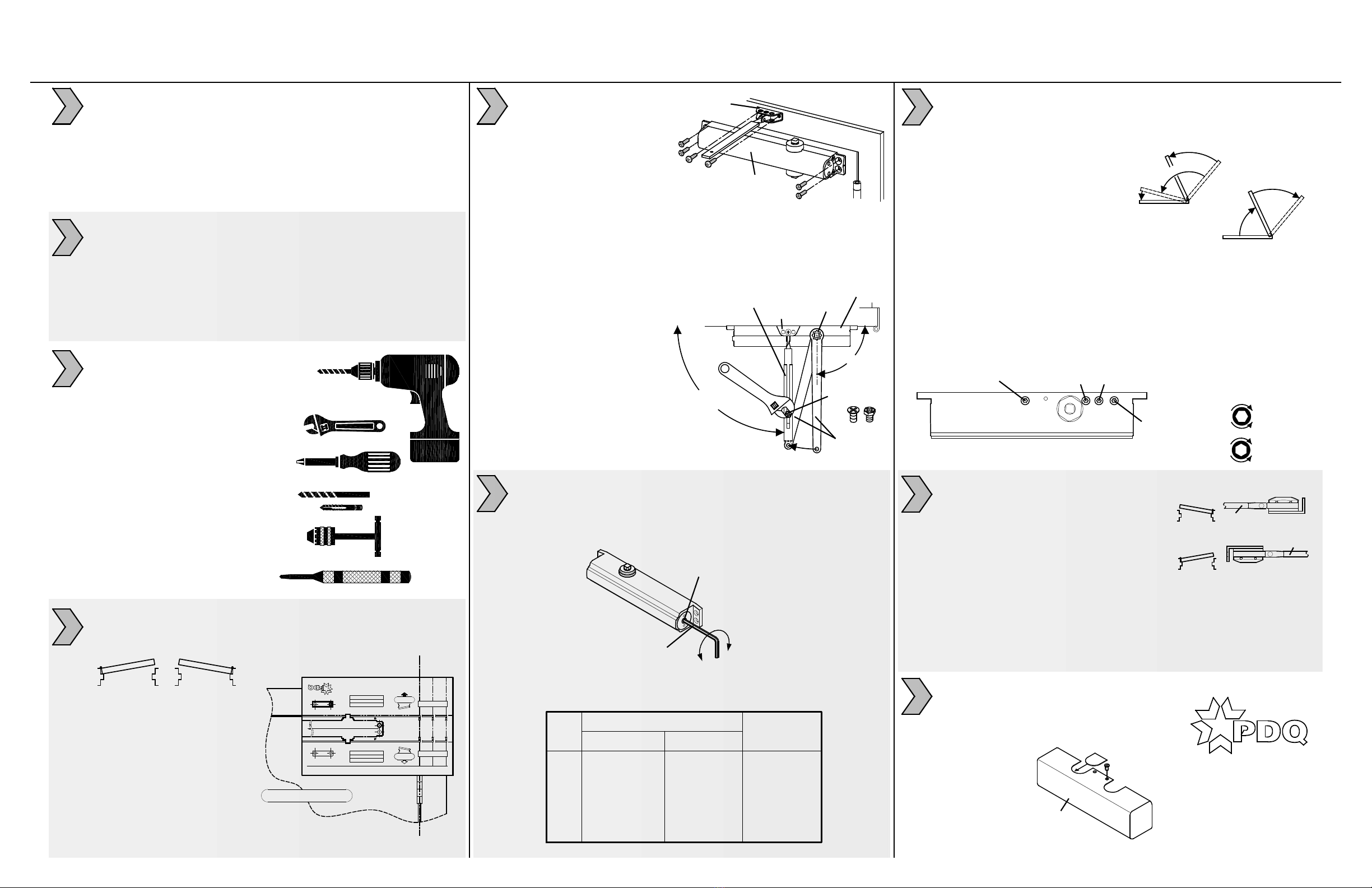
INSTALL 5100 COVER:
1. Align cover with closer spindle.
Slide insert into unused cutout.
2. Slide cover over closer until
flush with door face.
3. Secure with
screw
provided.
LH DOOR SHOWN
REGULAR ARM INSTALLATION - PULL SIDE - NON-HOLD OPEN AND HOLD OPEN APPLICATIONS
5300/5500 DOOR CLOSER MODELS INSTRUCTION SHEET TEMPLATE: 539351,
REV. 0 01-12-17
CLOSER BODY (RIGHT HAND DOOR)
CLOSER BODY (LEFT HAND DOOR)
FOOT
(RH DOOR)
THIS SIDE UP
FOR RH DOOR
THIS SIDE UP
FOR LH DOOR
FOOT
(LH DOOR)
LH RH
LH
RH
NUT DOWN
NUT UP
ARM
ARM
OPTIONAL HOLD OPEN ARM:
Important: DO NOT use arm as limiting
stop, separate dead stop is required.
Friction HO arm is not recommended
for doors frequently operated in/out
of hold open
1. Install hold-open foot/nut.
Left Hand (LH) door = Nut points down.
Right Hand (RH) door = Nut points up.
2. Loosen HO nut.
3. Open door several degrees before HO position.
4. Tighten nut.
PREPARE DOOR AND FRAME:
1. Determine maximum opening angle.
2. Determine door hand (LH or RH).
3. Align & attach
full size template
(see reverse side).
4. Mark door & frame
with center punch.
5. Remove template before
machining door & frame.
5100 DOOR CLOSER INSTRUCTION SHEET
REGULAR ARM INSTALLATION - PULL SIDE - NON-HOLD OPEN AND HOLD OPEN APPLICATIONS
REV. 2 09-06-19
ADJUST SPRING POWER:
1. Use 4 mm hex key provided to adjust to size on chart.
Clockwise (CW) turns increase spring power (+).
Counter-clockwise (CCW) turns decrease spring power (-).
6
1. Confirm this sheet is correct for your product and application.
2. Read the complete instruction sheet before starting installation.
3. Incorrectly installed or adjusted door closers can cause
personal injury or property damage.
4. To ensure safe operation, closers should be examined
and serviced regularly.
TOOLS REQUIRED:
1. Power drill
2. 10mm box/combo wrench
3. Phillips screw driver
4. #7 or 13/64" drill bit and
1/4-20 tap (machine screws)
5. Tap handle
6. 5/32" drill bit (wood screws)
7. 3/8" drill bit (sex nuts)
8. Center punch
1. See reverse side of this sheet to machine door & frame.
2. Dimensions based on 4-1/2" x 4-1/2" full mortise butt hinges
with 5/8" stop and 1/8" door gap.
3. Confirm door & frame are properly reinforced.
4. Sex nuts required for un-reinforced or composite fire doors.
5. Do not install closer on the exterior (weather) side of building.
1
2
3
4
INSTALL CLOSER AND ARM:
1. Attach closer body to door.
Spring adjustment nut points
away from hinge.
2. Attach foot to frame.
CLOSER
BODY
FOOT
5
ARM SCREW
OR BOLT
3. Secure main arm to closer spindle 90° to door/frame.
4. Connect adjustment arm with foot assembly:
Rotate main arm until adjustment arm is 90° to door & frame.
Tighten arm screw or bolt .
MAIN ARM
SPINDLE
ADJUSTMENT
ARM
PRELOAD
TO 90°
FOOT
CLOSER
90°
SLOWER
FASTER
INCREASE
DECREASE
1. Use hex key provided.
2. Adjust SWEEP (closing max.°- 10°).
3. Adjust LATCH (closing 10°- 0°).
4. Adjust BACKCHECK resistance (opening 70°- max.°).
DO NOT COMPLETELY CLOSE VALVE
5. Adjust (optional) DELAYED ACTION (closing max.°- 70°);
Provides additional hesitation for access (ADA/BF) through door.
CONTROL ADJUSTMENTS:
Closing time of 3-7 seconds is typical.
More time may be needed for ADA/BF access.
Clockwise (CW) = SLOWER.
Counter-clockwise (CCW) = FASTER.
DO NOT REMOVE VALVES
CLOSING CYCLE
Y
A
L
E
D
E
E
W
S
P
H
C
T
A
L
MAX.°
K
C
A
B
C
E
H
C
K
N
E
P
O
I
N
G
OPENING CYCLE
MAX.°
7
8
9
PDQ Manufacturing
2230 Embassy Dr.
Lancaster, PA 17603
833-273-7832
833-2 PDQTECH
www.pdqlocks.com


