manuals.online logo
Brands
  1. Home
  2. •
  3. Brands
  4. •
  5. GEZE
  6. •
  7. Security Sensor
  8. •
  9. GEZE GC 172 User manual

GEZE GC 172 User manual

GC 172
Wireless ceiling-mounted
smoke detector
EN Supplementary sheet
183121_01
Germany
GEZE GmbH
Niederlassung Süd-West
Tel. +49 (0) 7152 203 594
E-Mail: [email protected]
GEZE GmbH
Niederlassung Süd-Ost
Tel. +49 (0) 7152 203 6440
E-Mail: [email protected]
GEZE GmbH
Niederlassung Ost
Tel. +49 (0) 7152 203 6840
E-Mail: [email protected]
GEZE GmbH
Niederlassung Mitte/Luxemburg
Tel. +49 (0) 7152 203 6888
E-Mail: [email protected]
GEZE GmbH
Niederlassung West
Tel. +49 (0) 7152 203 6770
E-Mail: [email protected]
GEZE GmbH
Niederlassung Nord
Tel. +49 (0) 7152 203 6600
E-Mail: [email protected]
GEZE Service GmbH
Tel. +49 (0) 1802 923392
E-Mail: service-info[email protected]
Austria
GEZE Austria
E-Mail: [email protected]
www.geze.at
Baltic States –
Lithuania / Latvia / Estonia
E-Mail: [email protected]
Benelux
GEZE Benelux B.V.
E-Mail: [email protected]
www.geze.be
www.geze.nl
Bulgaria
GEZE Bulgaria - Trade
E-Mail: o[email protected]
www.geze.bg
China
GEZE Industries (Tianjin) Co., Ltd.
E-Mail: [email protected]
www.geze.com.cn
GEZE Industries (Tianjin) Co., Ltd.
Branch Oce Shanghai
E-Mail: [email protected]
www.geze.com.cn
GEZE Industries (Tianjin) Co., Ltd.
Branch Oce Guangzhou
E-Mail: [email protected]
www.geze.com.cn
GEZE Industries (Tianjin) Co., Ltd.
Branch Oce Beijing
E-Mail: [email protected]
www.geze.com.cn
France
GEZE France S.A.R.L.
E-Mail: [email protected]
www.geze.fr
Hungary
GEZE Hungary Kft.
E-Mail: oce-hungar[email protected]
www.geze.hu
Iberia
GEZE Iberia S.R.L.
E-Mail: info.es@geze.com
www.geze.es
India
GEZE India Private Ltd.
E-Mail: o[email protected]
www.geze.in
Italy
GEZE Italia S.r.l. Unipersonale
E-Mail: [email protected]
www.geze.it
GEZE Engineering Roma S.r.l
E-Mail: [email protected]
www.geze.it
Korea
GEZE Korea Ltd.
E-Mail: [email protected]
www.geze.com
Poland
GEZE Polska Sp.z o.o.
E-Mail: [email protected]
www.geze.pl
Romania
GEZE Romania S.R.L.
E-Mail: o[email protected]
www.geze.ro
Russia
OOO GEZE RUS
E-Mail: o[email protected]
www.geze.ru
Scandinavia – Sweden
GEZE Scandinavia AB
E-Mail: [email protected]
www.geze.se
Scandinavia – Norway
GEZE Scandinavia AB avd. Norge
E-Mail: [email protected]
www.geze.no
Scandinavia – Denmark
GEZE Danmark
E-Mail: [email protected]
www.geze.dk
Singapore
GEZE (Asia Pacic) Pte, Ltd.
E-Mail: [email protected]
www.geze.com
South Africa
GEZE South Africa (Pty) Ltd.
E-Mail: [email protected]
www.geze.co.za
Switzerland
GEZE Schweiz AG
E-Mail: [email protected]
www.geze.ch
Turkey
GEZE Kapı ve Pencere Sistemleri
E-Mail: o[email protected]
www.geze.com
Ukraine
LLC GEZE Ukraine
E-Mail: o[email protected]
www.geze.ua
United Arab Emirates/GCC
GEZE Middle East
E-Mail: [email protected]
www.geze.ae
United Kingdom
GEZE UK Ltd.
E-Mail: info.uk@geze.com
www.geze.com
GEZE GmbH
Reinhold-Vöster-Straße 21–29
71229 Leonberg
Germany
Tel.: 0049 7152 203 0
Fax: 0049 7152 203 310
www.geze.com
1 Safety instructions
To ensure personal safety, it is important to follow these
safety instructions. These instructions must be kept.
úBefore installation, read and observe the safety notes
for these components and the drive. Warranty claims
require proper mounting, installation and maintenance in
accordance with the manufacturer's specications.
úOnly appropriately qualied people may carry
out installation, commissioning and maintenance.
Unauthorised modications to the system release GEZE
from liability for any resulting damages.
úOnly use GEZE original parts for repair and service work.
úObserve the latest versions of guidelines, standards and
country-specic regulations.
úProtect the components of the GC172 from construction
dirt and water.
2 Brief description of wireless kit
The wireless kit is part of the GEZE hold-open system FA
GC150 or FA GC160.
The wireless module GC 171, ID 163051, makes wireless com-
munication possible between the lintel-mounted smoke
switch and the various wireless devices:
úWireless ceiling-mounted smoke detector GC172 ID 195522
úWireless ceiling-mounted thermal detector GC173 ID 195523
úWireless input module GC175, ID 163068 (for the connection of
manual trigger switches or contacts for the re alarm system)
3.2 Protection of the smoke detector from contamination
úDo not remove the dust protection cap from the smoke detector until commissioning is about to take place.
úAfter the smoke detector has been installed and the dust protection removed, make sure no dust gets into the measuring chamber.
This leads to increased contamination and can signicantly shorten the service life of the smoke detector.
úThe measuring chamber of a smoke detector must not be opened.
Heed the document for the hold-open system FA GC150 or FA GC160 - Instructions for the installation, commissioning, operation and
maintenance, see www.geze.com.
3.3 Technical data
Wireless ceiling-mounted smoke
detector GC172 ID 195522
comprising: úBase GC170 B
úWireless smoke detector GC002 F
úTwo batteries
Battery type CR 123A (3 V DC)
Colour White, RAL 9016
Dimensions (with base, Ø × H) 110 mm × 65 mm
Functional principle Scatter light, adaption of the alarm threshold, no alarm saving (self-resetting as soon as there is
no more smoke in the measuring chamber)
Insect grid Prevents insects getting into the measuring chamber
Installation position Ceiling mounting
IP rating (in accordance with EN 60529)
IP20, only for dry areas
Relative humidity 95% (non-condensing)
Ambient temperature -10 °C to 55 °C
Detector test To activate test mode:
XMove the test magnet near to the magnetic sensor (GEZE logo).
The LED ashes green.
Alarm triggering:
XMove the test magnet near to the magnetic sensor (GEZE logo) again.
XTrigger the alarm using the test aerosol.
The detector test using a test magnet tests the electrical components. The detector test which
forms part of the regular testing of the hold-open system must be carried out using a test aerosol
Battery life span 8 years
Signal transfer period 60 s
Antenna Integrated
Frequency range 868.15 MHz to 869.85 MHz
Range 10 m (100 m in space)
Number of frequency channels 7
Modulation technique FSK (frequency shift keying)
Radiated power 10 dBm / 10 mW
1
2
3
6
7
8
60
4 5
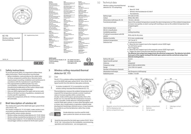
1 Magnetic sensor for testing (behind the GEZE logo)
2 LED for displaying state
3 Battery compartment cover
4 Battery compartment
5 Batteries
6 Set-up switch
7 Sabotage contact
8 Base
3 Wireless ceiling-mounted smoke
detector GC172
3.1 Use
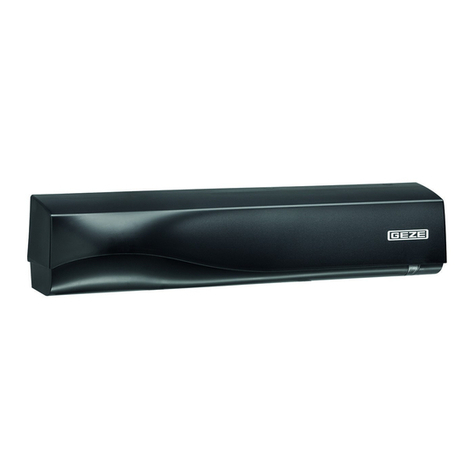
The GC172 is a wireless ceiling-mounted smoke detector for
use in the GEZE hold-open system FA GC150 or FA GC160.
Signal transfer from the detector takes place wirelessly.
A wireless module GC171 is essential for use of the
wireless ceiling-mounted smoke detector GC172.
Smoke detectors detect smoke. They work using the scat-
tered light principle. A light transmitter and a light interface
are arranged in the measuring chamber in such a way that
no light reaches the interface in the normal case. If there are
suspended particles (smoke) in the measuring chamber, these
scatter part of the light onto the interface, which converts this
into an electric signal.
In other words, a smoke detector not only detects smoke
but all other suspended particles and responds sensitively
to contamination.
Set up wireless connection
XSlide a free wireless device switch SW1x of the wireless module GC171 to the ON position.
The corresponding wireless device LED1x starts to ash green. If a connection has already
been set up for the wireless device switch selected, this is overwritten by the following pro-
cess. The wireless module GC171 waits for the connection query for a new wireless device.
If a new wireless device does not respond within 2 minutes, the wireless module GC171
cancels the connection attempt, the corresponding wireless device LED1x lights up red.
XTo start the connection attempt again, slide the corresponding wireless device switch
SW1x to the OFF position briey, then slide it back into the ON position.
The corresponding wireless device LED1x now ashes green again for 2 minutes.
LED1x
SW1x
Install batteries
XRemove the protective lms from the battery compartment (4) of the new wireless detec-
tor and install the batteries (5) in the new wireless detector. Make sure of correct polarity.


The LED (2) on the new wireless ceiling-mounted detector ashes green twice rst, then
lights up orange for one second and then ashes red four times.
As soon as the LED (2) goes out after that, the connection can be set up.
2
XSlide the set-up switch (6) on the new wireless detector to the 1 position.
After a short time, the LED of the new wireless detector will ash green for a few seconds.
The corresponding wireless device LED1x of the wireless module GC171 lights up green
permanently.

If the LED (2) on the new wireless detector lights up red permanently, no connection has
been made.
XIn this case, remove the batteries from the new wireless detector, slide the set-up
switch (6) on the new wireless detector back and forward six times and install the bat-
teries (5) again. Continue as described above.
XFit the wireless ceiling-mounted smoke detector to the base (8).
XSlide the wireless device switch SW1x of the wireless module GC171 to the OFF
position again.
The colour the corresponding wireless device LED1x ashes indicates the quality of
the wireless connection (see connection quality).
XOptimise the quality of the wireless connection if necessary by changing the
position of the wireless detector.
LED1x
SW1x
The connection of the wireless module GC171 to the new wireless detector has been set up.
XNote the set-up connection (the number of the assigned wireless device switch)
onto the identication plate of the new wireless detector.
XTo set up further wireless connections, continue with step “Set up wireless connection”.
XPress the PB1 push button on the wireless module GC171 briey to change to the
“operating” mode.
The status LED2 of the wireless module GC171 goes o.
1
2
3
4
KL1 SW1 LED1
24V
GND
MRB
AS
1
2
3
4
LED2
PB1 SW2
GC161 GC151
KL1 SW1 LED1
24V
GND
MRB
AS
1
2
3
4
LED2
PB1 SW2
GC161 GC151
EN 54-7*
EN 54-25*
EN 14637**
* EN 54-7 and EN 54-25 certied by BRE Global Ireland only with the GC171_L gateway (see document L20-GC171_-0001_REV_A.1).
** EN 14637 certied by KRIWAN with GC 172, GC 173, GC 175 and GC171 gateway.
3.4 Signalling
State, event LED for displaying state
Switch on lights up green for 1 s, then repeated red
Start set-up of the wireless connection ashes green until the wireless connection is established
Fault during set-up of the wireless connection lights up red
Operation o
Alarm ashes red (0.5s on – 0.5s o)
Battery 1 discharged ashes orange (0.1s on – 5s o)
Battery 2 discharged ashes green (0.1s on – 5s o)
Both batteries discharged ashes orange/green alternately (0.1s on – 5s o)
Other faults ashes orange/green alternately (0.5s each)
Manipulation o
Loss of connection o
Test mode – the detector reacts sensitively to aerosol pulses ashes green every second for 1 minute
3.5 Battery replacement
The wireless detector signals “low battery charge” to the wireless module GC171 if the charge state of the batteries
is no longer
sucient. Both batteries (5) always have to be replaced together. The set-up switch (6) for the wireless detector must not be activated.
XTake the wireless detector out of the base (8).
XRemove the battery compartment cover (3).
XRemove both batteries (5).
XInsert new batteries (type CR123A) – make sure polarity is correct.
XReplace the battery compartment cover (3).
XInsert the wireless detector into the base (8).
XTest the wireless detector. It can take up to a minute for the wireless detector to be ready for operation after battery replacement.
3.6 Connecting the wireless ceiling-mounted smoke detector GC172 to wireless module GC171
A maximum of 6 wireless connections can be set up at one wireless module GC171.
Pre-conditions
úAll the wireless device switches of the wireless module GC171 are in the OFF position.
SW1x
úThe set-up switch (6) of the new wireless detector is set to the ON position.

úThe protective lms are on the battery compartment of the new wireless detector
and the batteries for the new wireless detector have not been tted.
Set up a new wireless connection
XSwitch the supply voltage for the wireless module GC171 on.
The wireless module is in “operating” mode.
XPress the PB1 push button on the wireless module GC171 briey to change to the “set
up wireless connection” mode. The status LED2 of the wireless module GC171 now
lights up red permanently.
1
2
3
4
KL1 SW1 LED1
24V
GND
MRB
AS
1
2
3
4
LED2
PB1
SW2
GC161 GC151
KL1 SW1 LED1
24V
GND
MRB
AS
1
2
3
4
LED2
PB1 SW2
GC161 GC151
GEZE GmbH hereby declares that the components of the wireless kit for hold-open systems complies with the Directives
2014/53/EU and 2011/65/EU. The complete text of the EU Declaration of Conformity, and the Declaration of Performance, is
available at the following internet address: www.geze.com

Other GEZE Security Sensor manuals

GEZE GC 363 R User manual

GEZE

GEZE GC 363 R User manual

GEZE SecuLogic RWS TZ 300 Operator's manual

GEZE

GEZE SecuLogic RWS TZ 300 Operator's manual

GEZE GC 307+ User manual

GEZE

GEZE GC 307+ User manual

GEZE GC 304 R User manual

GEZE

GEZE GC 304 R User manual

GEZE GC 173 User manual

GEZE

GEZE GC 173 User manual

GEZE GC 173 User manual

GEZE

GEZE GC 173 User manual

GEZE GC 333 C User manual

GEZE

GEZE GC 333 C User manual

GEZE GC 365 R User manual

GEZE

GEZE GC 365 R User manual

GEZE GC 334 User manual

GEZE

GEZE GC 334 User manual

GEZE GC 304 R User manual

GEZE

GEZE GC 304 R User manual

Popular Security Sensor manuals by other brands

Powerfix Profi 288019 Operation and safety notes

Powerfix Profi

Powerfix Profi 288019 Operation and safety notes

Skyhawk Kiwi IR Installation & user manual

Skyhawk

Skyhawk Kiwi IR Installation & user manual

Siemens QRI Series quick start guide

Siemens

Siemens QRI Series quick start guide

rayence 1417WGC User & installation manual

rayence

rayence 1417WGC User & installation manual

GE VE1100 Series Installation sheet

GE

GE VE1100 Series Installation sheet

Satel AXD-200-DG user manual

Satel

Satel AXD-200-DG user manual

BTG Mutek PCD-05 Smart Operation manual

BTG

BTG Mutek PCD-05 Smart Operation manual

RAKSA iDet user manual

RAKSA

RAKSA iDet user manual

bianco SK3 user manual

bianco

bianco SK3 user manual

KingShield OD103 Installation

KingShield

KingShield OD103 Installation

nvent RAYCHEM TraceTek TTDM Series installation instructions

nvent

nvent RAYCHEM TraceTek TTDM Series installation instructions

ISC RP203 General Instructions for Use

ISC

ISC RP203 General Instructions for Use

Velleman ZLUV220 user manual

Velleman

Velleman ZLUV220 user manual

Thinkcar PLD-212 user manual

Thinkcar

Thinkcar PLD-212 user manual

BEA ACTIV8 ONE ON quick start guide

BEA

BEA ACTIV8 ONE ON quick start guide

Extech Instruments EzFlex EZ40 user manual

Extech Instruments

Extech Instruments EzFlex EZ40 user manual

netvox R718B user manual

netvox

netvox R718B user manual

Telefire TBD-8100 Technical manual

Telefire

Telefire TBD-8100 Technical manual

manuals.online logo
manuals.online logoBrands
  • About & Mission
  • Contact us
  • Privacy Policy
  • Terms and Conditions

Copyright 2025 Manuals.Online. All Rights Reserved.