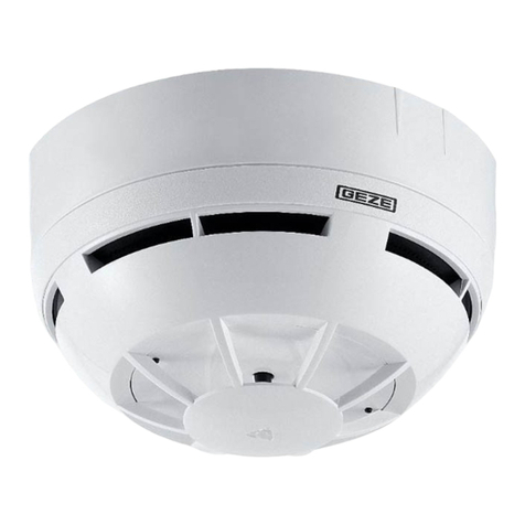
GEZE GC 173 User manual

GC 173
Wireless ceiling-mounted
thermal detector
183155
-00
EN Supplementary sheet
1 Brief description of wireless kit
The wireless kit is part of the GEZE hold-open system FA GC
150 or FA GC 160.
The wireless module GC 171, ID 163051, makes wireless
communication possible between the lintel-mounted smoke
switch and the various wireless devices.
àWireless ceiling-mounted smoke detector GC 172, ID 159656
àWireless ceiling-mounted thermal detector GC 173, ID 159657
àWireless input module GC 175, ID 163068 (for the connection of
manual trigger switches or contacts for the re detector system)
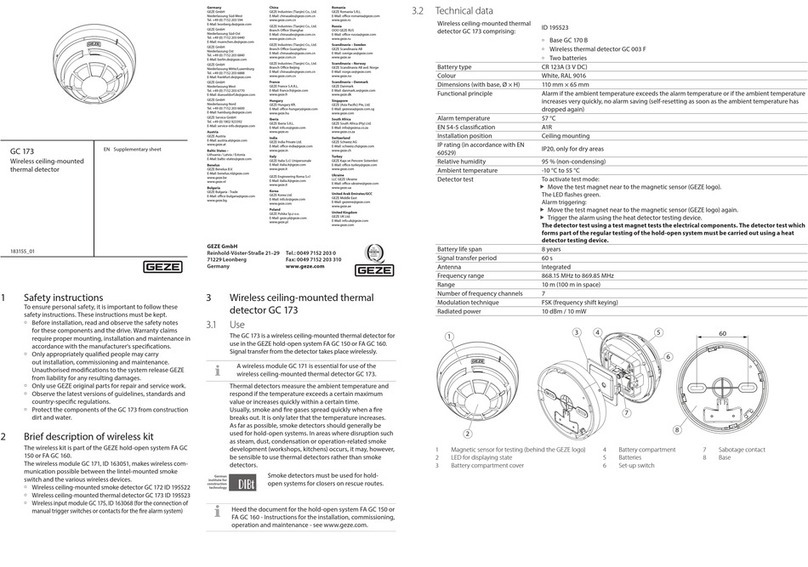
2.2 Technical data
Wireless ceiling-mounted thermal ID 159657
detector GC 173 comprising: Base GC 170 B
Wireless thermal detector GC 003 F
Main battery and slave battery
Wireless thermal detector GC 003 F ID 163049
Battery set (spare) ID 163228
Main battery Type CR 123A (3 V DC)
Slave battery Type CR 2032A (3 V DC)
Colour white, RAL 9016
Dimensions (with base, dia. x H) 110 mm x 65 mm
Functional principle Alarm if the ambient temperature exceeds the alarm temperature or if the ambient
temperature increases very quickly, no alarm saving (self-resetting as soon as the ambient
temperature has dropped again)
Alarm temperature 57°C
EN 54-5 classication A1R
Installation position Ceiling mounting
IP rating (in accordance with EN 60529) IP20, only for dry areas
Ambient temperature -5°C to 50°C
Detector test Alarm actuation
- using test magnet near the magnetic sensor (GEZE logo)
- with heat detector testing device
The detector test using a test magnet tests the electrical components. The detector
test which forms part of the regular testing of the hold-open system must be carried
out using a heat detector testing device.
Service life main battery 5 years
Signal transfer period 60 s
Antenna integrated
Frequency range 868.15 MHz to 869.85 MHz
Range 10 m (100 m in space)
Quantity Frequency channels 7
Modulation technique FSK (frequency shift keying)
Radiated power 5 dBm (3 mW)
1
2
CR2032 CR123A
8
6
7
5
3
4
60
50
9
1 Magnetic sensor for testing (behind the GEZE logo)
2 LED for displaying state
3 Set-up switch
4 Sabotage contact
5 Battery compartment
6 Main battery
7 Slave battery
8 Battery compartment cover
9 Base
2 Wireless ceiling-mounted thermal
detector GC 173
2.1 Use
The GC 173 is a wireless ceiling-mounted thermal detector
for use in the GEZE hold-open system FA GC 150 or
FA GC 160. Signal transfer from the detector takes place
wirelessly.
A wireless module GC 171 is essential for use of the wire-
less ceiling-mounted thermal detector GC 172.
Thermal detectors measure the ambient temperature and
respond if the temperature exceeds a certain maximum
value or increases quickly within a certain time.
Usually, smoke and re gases spread quickly when a re
breaks out. It is only later that the temperature increases.
As far as possible, smoke detectors should generally be used
for hold-open systems. In areas where disruption such as
steam, dust or operationally caused smoke development
(workshops, kitchens) occurs, it may, however, be sensible to
use thermal detectors rather than smoke detectors.
Smoke detectors must be used for hold-open system doors
on escape routes.
Heed the document for the hold-open system FA GC 150
or FA GC 160 - Instructions for the installation, commis-
sioning, operation and maintenance
,
see www.geze.com.
Germany
GEZE GmbH
Niederlassung Süd-West
Tel.+49 (0) 7152 203 594
E-Mail:leonberg.de@geze.com
GEZE GmbH
Niederlassung Süd-Ost
Tel.+49 (0) 7152 203 6440
E-Mail:muenchen.de@geze.com
GEZE GmbH
Niederlassung Ost
Tel.+49 (0) 7152 203 6840
E-Mail:berlin.de@geze.com
GEZE GmbH
Niederlassung Mitte/Luxemburg
Tel.+49 (0) 7152 203 6888
E-Mail:frankfurt.de@geze.com
GEZE GmbH
Niederlassung West
Tel.+49 (0) 7152 203 6770
E-Mail:duesseldorf.de@geze.com
GEZE GmbH
Niederlassung Nord
Tel.+49 (0) 7152 203 6600
E-Mail:hamburg.de@geze.com
GEZE Service GmbH
Tel.+49 (0) 1802 923392
E-Mail:service-info.de@geze.com
Austria
GEZE Austria
E-Mail:austria.at@geze.com
www.geze.at
Baltic States
www.geze.com
Benelux
GEZE Benelux B.V.
E-Mail:benelux.nl@geze.com
www.geze.be
www.geze.nl
Bulgaria
GEZE Bulgaria -Trade
www.geze.bg
China
GEZE Industries (Tianjin) Co., Ltd.
E-Mail:chinasales@geze.com.cn
www.geze.com.cn
GEZE Industries (Tianjin) Co., Ltd.
E-Mail:chinasales@geze.com.cn
www.geze.com.cn
GEZE Industries (Tianjin) Co., Ltd.
E-Mail:chinasales@geze.com.cn
www.geze.com.cn
GEZE Industries (Tianjin) Co., Ltd.
E-Mail:chinasales@geze.com.cn
www.geze.com.cn
France
GEZE France S.A.R.L.
E-Mail:france.fr@geze.com
www.geze.fr
Hungary
GEZE Hungary Kft.
www.geze.hu
Iberia
GEZE Iberia S.R.L.
E-Mail:info@geze.es
www.geze.es
India
GEZE India Private Ltd.
www.geze.in
Italy
GEZE Italia S.r.l
E-Mail:italia.it@geze.com
www.geze.it
GEZE Engineering Roma S.r.l
E-Mail:roma@geze.biz
www.geze.it
Poland
GEZE Polska Sp.z o.o.
E-Mail:geze.pl@geze.com
www.geze.pl
Romania
GEZE Romania S.R.L.
www.geze.ro
Russia
OOO GEZE RUS
www.geze.ru
Scandinavia – Sweden
GEZE Scandinavia AB
E-Mail:sverige.se@geze.com
www.geze.se
Scandinavia – Norway
GEZE Scandinavia AB avd. Norge
E-Mail:norge.se@geze.com
www.geze.no
Scandinavia – Denmark
GEZE Danmark
E-Mail:danmark.se@geze.com
www.geze.dk
Singapore
E-Mail:gezesea@geze.com.sg
www.geze.com
South Africa
GEZE South Africa (Pty) Ltd.
E-Mail:info@gezesa.co.za
www.geze.co.za
Switzerland
GEZE Schweiz AG
E-Mail:schweiz.ch@geze.com
www.geze.ch
Turkey
GEZE Kapı ve Pencere Sistemleri
www.geze.com
Ukraine
LLC GEZE Ukraine
www.geze.ua
United Arab Emirates/GCC
GEZE MiddleEast
E-Mail:gezeme@geze.com
www.geze.ae
United Kingdom
GEZE UK Ltd.
E-Mail:info.uk@geze.com
www.geze.com
GEZE GmbH
Reinhold-Vöster-Straße 21–29
71229 Leonberg
Germany
Tel.: 0049 7152 203 0
Fax: 0049 7152 203 310
www.geze.com
X6. Slide a free wireless device switch SW1x of the wireless module GC 171
to the ON position. The corresponding wireless device LED1x starts to ash
green. If a connection has already been set up for the wireless device switch
selected, this is overwritten by the following process. The wireless module
GC 171 waits for the connection query for a new wireless device. If a new
wireless device does not respond within 2 minutes, the wireless module GC
171 cancels the connection attempt, the corresponding wireless device LED1x
lights up red. To start the connection attempt again, slide the corresponding
wireless device switch SW1x to the OFF position briey, then slide it back into
the ON position. The corresponding wireless device LED1x now ashes green
again for 2 minutes.
LED1x
SW1x
X7. Remove the protective lm from the battery compartment of the new wire-
less detector and install the main battery in the new wireless detector. Make
sure of correct polarity.
The LEDs of the new wireless ceiling-mounted detector ash green twice
rst, then light up yellow for one second and then ash red four times. As
soon as the LED goes out after that, the connection can be set up.
X8. Now slide the set-up switch on the new wireless detector to the OFF posi-
tion. After a short time, the LED of the new wireless detector will ash green
for a few seconds. The corresponding wireless device LED1x of the wireless
module GC 171 lights up green permanently.
X9. If the LED on the new wireless detector lights up red permanently, no con-
nection has been made. In this case, remove the main battery from the new
wireless detector, slide the set-up switch on the new
wireless detector back
and forward 6 times and start again with step 7.
X10. Fit the wireless ceiling-mounted detector to the base.
X11. Slide the wireless device switch SW1x of the wireless module GC 171
to the OFF position again. The colour the corresponding wireless device
LED1x ashes indicates the quality of the wireless connection (see con-
nection quality). Optimise the quality of the wireless connection if neces-
sary by changing the position of the wireless detector.
LED1x
SW1x
X12. The connection of the wireless module GC 171 to the new wireless
detector has been set up.
XNote the set-up connection (the number of the assigned wireless device
switch) onto the identication plate of the new wireless detector.
XTo set up further wireless connections, continue with step 6.
X13. Press the PB1 push button on the wireless module GC 171 briey to
change to the “operating” mode. The status LED2 of the wireless module
GC 171 goes o.
1
2
3
4
PB1
LED2
2.3 Signalling
State, event LED for displaying state
Switch on
after removal of the insulation lm or after the main
battery has been inserted
ashes 1 x green, then red for approx. 1 min, then green briey, then the LED is
o
Start set-up of the wireless connection ashes 2 x green, 1 x yellow, 4 x red
Fault during set-up of the wireless connection red
Operation o
Main battery discharged ashes yellow (0.1 s on – 5 s o)
Slave battery discharged ashes green (0.1 s on – 5 s o)
Main and slave batteries discharged ashes yellow/green alternately (0.1 s on – 5 s o)
Other faults ashes yellow/green alternately (0.5 s o each)
Alarm ashes red (0.5 s on – 0.5 s o)
2.4 Battery replacement
The wireless detector signals “Low battery charge” to the wireless module GC 171 if the charge state of the batteries is no longer
sucient. Both batteries (main battery and slave battery) always have to be replaced together. The set-up switch for the wireless
detector must not be activated.
X1. Take the wireless detector from the base.
X2. Use a small screwdriver to remove the battery compartment cover.
X3. Remove the main battery.
X4. Use a small screwdriver to carefully remove the slave battery. Ensure that the PCB does not become damaged.
X5. Slide the new slave battery (type CR2032A) into place – the positive pole faces upwards.
X6. Insert the new main battery (type CR123A) – make sure polarity is correct.
X7. Fit the battery compartment cover back in lace.
X8. Insert the wireless detector into the base.
X9. Test the wireless detector. It can take up to a minute for the wireless detector to be ready for operation after battery replacement.
2.5 Connect the wireless ceiling-mounted thermal detector GC 173 to wireless module GC 171
Set up a new wireless connection
A maximum of 6 wireless connections can be set up at one wireless module GC 171:
X1. All the wireless device switches of the wireless module
GC 171 are in the OFF position. SW1x
X2. The set-up switch of the new wireless detector is set to the ON position.
X3. The protective lm is on the battery compartment of the new wireless de-
tector and the main battery for the new wireless detector has not been tted.
X4. After the supply voltage has been switched on, the wireless module GC 171
is in “operating” mode.
X5. Press the PB1 push button on the wireless module GC 171 briey to change
to the “set up wireless connection” mode. The status LED2 of the wireless
module GC 171 is now permanently lit red.
1
2
3
4
PB1
LED2
EN 54-5
EN 54-25
EN 14637
Other GEZE Security Sensor manuals

GEZE
GEZE GC 365 R User manual

GEZE
GEZE GC 363 R User manual

GEZE
GEZE GC 333 C User manual

GEZE
GEZE GC 304 R User manual

GEZE
GEZE GC 173 User manual

GEZE
GEZE GC 172 User manual

GEZE
GEZE GC 334 User manual

GEZE
GEZE GC 307+ User manual

GEZE
GEZE GC 304 R User manual

GEZE
GEZE SecuLogic RWS TZ 300 Operator's manual
Popular Security Sensor manuals by other brands

q-Tech
q-Tech XLINE Series Installation and programming manual

Redline
Redline RAS-Extend M Installation guidelines

Innohome
Innohome Stove Guard SGK430 Reference manual

EPE Conseil
EPE Conseil CEMPROTEC 34 user guide

Paradox
Paradox EB-N94 installation guide

C.P. Electronics
C.P. Electronics MWS6-DD-LV installation guide